

Arctic Cat Sno Pro 600 2013 Operator/Service Manual
6

Limited Warranty
Arctic Cat Inc. (hereinafter referred to as Arctic Cat) extends a limited warranty as described below on each new Arctic Cat Snowmobile it assembles and on each
genuine Arctic Cat Snowmobile part and accessory assembled and sold by an authorized Arctic Cat Snowmobile dealer. The limited warranty on an Arctic Cat
Snowmobile is extended to the original retail purchaser for the time periods described below; however, the balance of the remaining warranty may be transferred to
another party unless the purchase is for commercial use (see below). Warranty coverage is only available in the country in which the original retail purchase occurs
to the original retail purchaser resident in that country or to a transferee resident in that country of the balance of the remaining warranty.
Arctic Cat warrants only the products it assembles and/or sells and does not warrant that other products will function properly when used with an Arctic Cat
Snowmobile or will not damage the Arctic Cat Snowmobile. Arctic Cat does not assume any liability for incidental or consequential damages.
Arctic Cat will repair or replace, at its option, free of charge (including any related labor charges), any parts that are found to be warrantable in material or workmanship.
This repair work MUST be done by an authorized Arctic Cat Snowmobile dealer. No transportation charges, rental charges, or inconvenience costs will be paid by Arctic
Cat. The warranty is validated upon examination of said parts by Arctic Cat or an authorized Arctic Cat Snowmobile dealer. Arctic Cat reserves the right to inspect such
parts at its factory for final determination if warranty should apply.
The warranty periods are as follows:
1. For snowmobiles used for recreational purposes:
—If purchased between May 1 and November 30, warranty expires ONE (1) YEAR from December 1 of the current year.
—If purchased between December 1 and April 30, ONE (1) YEAR from the date of sale.
2. For snowmobiles used for commercial purposes (including rental operations), ONE (1) YEAR from the date of invoice and/or 5000 MILES whichever comes first
(non-transferable).
3. THIRTY (30) DAYS from date of sale of snowmobile on Arctic Cat supplied batteries.
Exclusions to this warranty include normal wear, abuse (i.e. a track run on marginal snow conditions without proper lubrication or additional idler wheels), and the
following parts:
Fuel Filter Light Bulbs Windshield Drive Belt Torn or Punctured Upholstery
Wear Bars Brake Pads Spark Plugs Drive Clutch/Driven Clutch Wear Parts
Wear Strips Shock Absorber(s) - Standard* Shock Absorber(s) - Rebuildable**
* Limited to one (1) year or 1000 miles of “normal” riding conditions - replace for defective or leaking shock, corroded or pitted shaft, peeling chrome.
** Limited to one (1) year or 1000 miles of “normal” riding conditions - rebuild for leaking shock (warranted) - replace for defective shock, corroded or pitted shaft, peeling
chrome.
The following will VOID Arctic Cat’s warranty:
1. Failure to perform the proper break-in procedure and all related maintenance, storage procedures (if stored for extended periods), and/or service as
recommended in the Operator’s Manual.
2. Repairs and/or adjustments by anyone other than an authorized Arctic Cat Snowmobile dealer.
3. Use of an improper fuel mixture ratio.
4. Use of improper carburetor jets.
5. Use of improper gasoline, lubricating oils, or spark plugs.
6. An accident or subjecting the snowmobile to misuse, abuse, or negligent operation.
7. Any modification, addition, or removal of parts unless instructed to do so by Arctic Cat.
8. Use of the snowmobile in any way for racing purposes.
9. Removal of the engine for use in another vehicle.
10. Removal or mutilation of the Vehicle Identification Number or Engine Serial Number.
11. Use of parts not sold or approved by Arctic Cat.
12. Track and tunnel damage resulting from either ice stud or hooker plate installation.
13. Damage due to improper transportation.
Arctic Cat shall not be responsible for and this limited warranty excludes recovery of economic, punitive, consequential and incidental damages, lost profits, and loss
of use. Some states or provinces do not allow the exclusion or limitation of incidental or consequential damages, so the above limitation may not apply to you. Arctic
Cat’s aggregate liability may not exceed the price of the product. The law of the State of Minnesota shall apply to all claims or disputes, exclusive of its conflicts of
law provisions.
IMPLIED WARRANTY EXCLUSION AND DISCLAIMER
To the fullest extent permitted by law, Arctic Cat excludes and disclaims all implied warranties of merchantability and fitness for a particular purpose.
If you are not satisfied with warranty service or repairs, you should contact Arctic Cat at (U.S.) 1-218-681-9851 or (Canada) 1-204-982-1656.

FOREWORD
Congratulations! You have chosen a quality Arctic Cat Snowmobile designed and manufactured to give dependable service. Be sure, as the owner/operator of an Arctic Cat Snowmobile, to become thoroughly familiar with its
basic operation, maintenance, and off-season storage procedures. Read this manual and the accompanying Snowmobile Safety Handbook before operating the snowmobile to ensure safe and proper use of your new Arctic Cat
Snowmobile. Always operate the snowmobile within your level of skill and current terrain conditions.
The Operator’s Manual, Snowmobile Safety Handbook, and snowmobile decals display the words Warning, Caution, and Note to emphasize important information. The symbol
related information. Be sure to follow the directive because it deals with the possibility of severe personal injury or
even death. A CAUTION identifies unsafe practices which may result in snowmobile-related damage. Follow
the directive because it deals with the possibility of damaging part or parts of the snowmobile. The symbol
NOTE: identifies supplementary information worthy of particular attention.
This manual covers operator-related maintenance, operating instructions, and off-season storage instructions. If
major repair or service is ever required, contact an authorized Arctic Cat Snowmobile dealer for professional service.
At the time of publication, all information and illustrations were technically correct. Some illustrations used in this
manual are used for clarity purposes only and are not designed to depict actual conditions. Because Arctic Cat Inc.
constantly refines and improves its products, no retroactive obligation is incurred.
This Operator’s Manual should be considered a permanent part of the snowmobile and must remain with the snowmobile at the time of resale. If the snowmobile changes ownership more than once, contact Arctic Cat Inc., Service
Department, P.O. Box 810, Thief River Falls, MN 56701, for proper registration information.
! WARNING identifies personal safety-
Every Arctic Cat Snowmobile meets or exceeds the standards of the Snowmobile Safety and Certification Committee and displays the SSCC decal. Arctic Cat endorses and encourages the safe use of all snowmobiles. Always wear
a helmet and eye protection. Drive with caution, observe all state and local regulations, and respect the rights of
others. ISMA members like Arctic Cat do their part to improve trails, sponsor events, and generally support the
sport of snowmobiling. As a member of the National Snowmobile Foundation, Arctic Cat Inc. promotes snowmobiling through education, charity, and research programs.
© 2012 Arctic Cat Inc.
Printed in U.S.A. October 2012
! WARNING
This snowmobile is a very high performance snowmobile. Because it does accelerate rapidly and is capable
of very high speeds, it should not be operated by a
novice or an inexperienced operator. Never accelerate
rapidly or drive at high speed beyond the limits of visibility or without being totally familiar with the terrain
and what lies in front of you. Obey speed limits and
never operate at speeds that do not allow adequate
maneuvering and stopping distances. Read and study
the entire Operator’s Manual and Safety Handbook.
Failure to follow this warning could result in personal
injury to yourself or others.
PARTS AND ACCESSORIES
When in need of replacement parts, oil, or accessories for your Arctic Cat Snowmobile, be sure to only
use GENUINE ARCTIC CAT PARTS, OIL, AND
ACCESSORIES. Only genuine Arctic Cat parts, oil,
and accessories are engineered to meet the standards
and requirements of your Arctic Cat Snowmobile.
For a complete list of accessories, refer to the current
Arctic Cat Accessory Catalog.
To aid in service and maintenance procedures on this
snowmobile, an Illustrated Parts Manual is available
through your local Arctic Cat Snowmobile dealer.
If the snowmobile is purchased
through the Team Arctic Race
Department Racing Program, there
is no warranty.
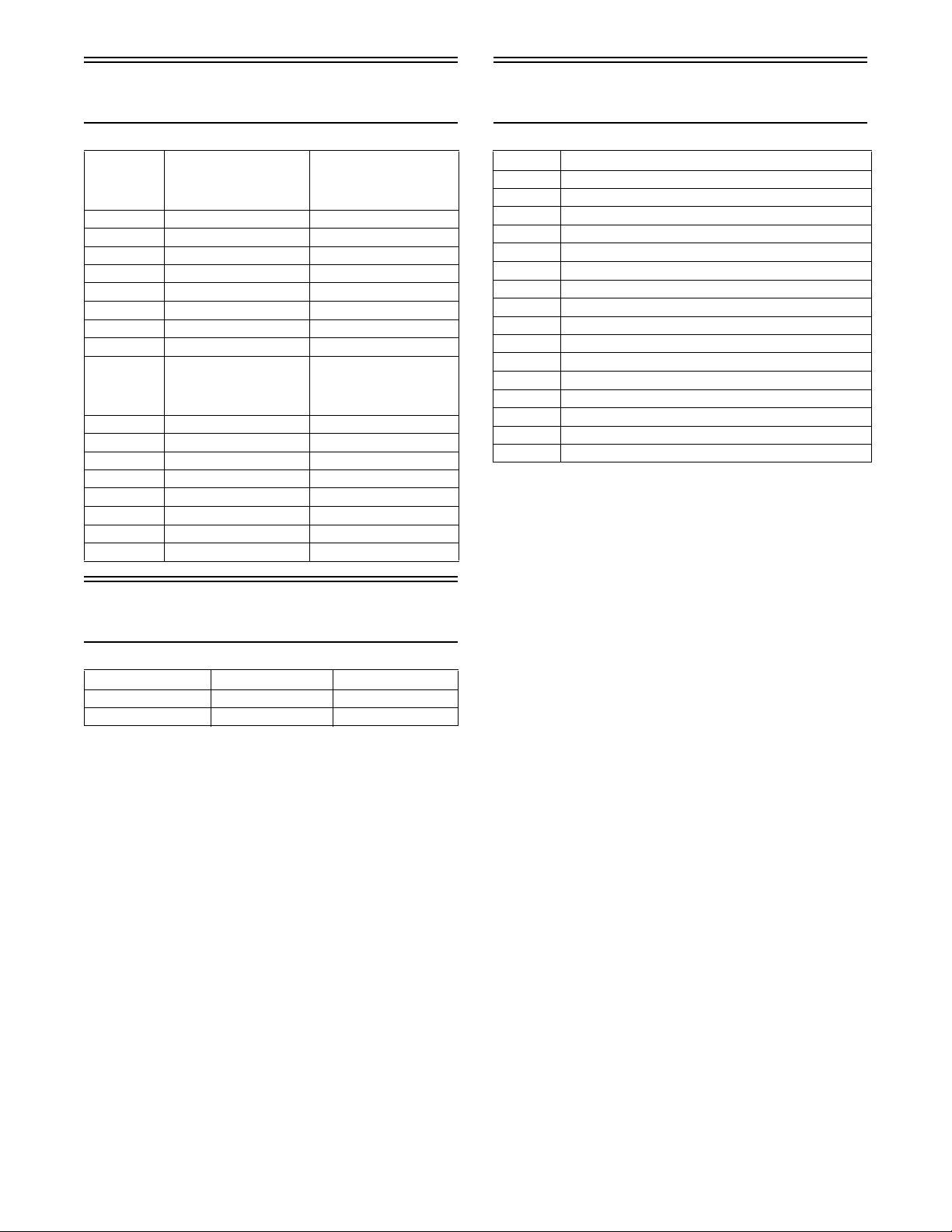
Reference Information
The Arctic Cat Snowmobile has two important identification numbers. The Vehicle Identification Number
(VIN) is stamped on the side of the tunnel. The Engine
Serial Number (ESN) is stamped into the crankcase of
the engine.
0746-482
These numbers are required by the dealer to complete
warranty claims properly. No warranty will be allowed
by Arctic Cat Inc. if the engine serial number or VIN is
removed or mutilated in any way.
Always provide the snowmobile name, VIN, and ESN
when contacting an authorized Arctic Cat Snowmobile
dealer for parts, service, accessories, or warranty. If
the complete engine must be replaced, ask the dealer to
notify Arctic Cat for correct registration information.
Write the appropriate information for your Arctic Cat
Snowmobile in the spaces below. Always use these
numbers when referring to your snowmobile.
Model: ____________________________________
Date of Purchase: ____________________________
VIN (Vehicle Identification Number): ____________
ESN (Engine Serial Number):___________________
Your Arctic Cat Dealer: ______________________
Address: ___________________________________
Phone: ____________________________________

TABLE OF CONTENTS
Specifications/Charts/Patterns/Diagrams ............. 2-21
General Specifications ............................................ 2
Engine Specifications ............................................. 2
Torque Specifications.............................................. 2
Engine Torque Patterns .......................................... 4
Torque Conversions (ft-lb/N-m) ............................... 4
Tightening Torque (General Bolts) .......................... 4
Electrical Specifications .......................................... 5
Component Voltage/Resistance Chart - Water
Temperature ........................................................ 5
Crankshaft Runout/Repair Specifications ............... 6
Drive System Specifications ................................... 6
Drive Clutch/Driven Clutch Optional Components .. 7
Drive Clutch Spring Chart ....................................... 7
Drive Clutch Cam Arms (w/Set Screw)................... 7
Chain Case Performance Calibrations.................... 8
Chains and Sprockets............................................. 9
Carburetor Specifications........................................ 9
Arctic Power Valve (APV) System Specifications ... 9
Mikuni Tuning Components .................................. 10
Major Tuning Components.................................... 11
Jet Needle Taper Angles....................................... 11
Rear Spring Selection Chart ................................. 11
Installed Spring Rate Chart .................................. 12
Front Suspension Sway Bar.................................. 12
Rebuildable Shock Tools Required ....................... 12
Valve Stacks/Specifications (Sno Cross) .............. 13
Valve Stacks/Specifications (Cross Country) ........ 15
Rebuildable Shock Accessory Part Numbers ....... 17
Fraction/Decimal Conversion Chart ...................... 18
Drill Bit Sizes (Number) Chart............................... 18
MM/IN. Conversion Chart ..................................... 18
Wiring Diagram - Hood Harness ........................... 19
Wiring Diagram - Ignition/Main Harness ............... 21
Setup Instructions ............................................... 23-30
Removing Snowmobile From Crate/Handlebar
Assembly ........................................................... 23
Installing Windshield ............................................ 23
Installing Spindle/A-Arm ....................................... 23
Installing Front Shock Absorbers .......................... 23
Installing Skis........................................................ 23
Installing Sway Bar (Optional)............................... 24
Brake System........................................................ 24
Drive Belt .............................................................. 24
Ski Alignment ........................................................ 25
Recommended Gasoline/Oil/Mixing Ratio ............ 26
Preoperation Checks ............................................ 27
Checking Headlight Aim........................................ 27
Track Tension/Track Alignment.............................. 27
Handlebar/Ski Alignment ...................................... 28
Test Ride ............................................................... 30
General Information ............................................ 31-35
Control Locations .................................................. 31
Engine Break-In .................................................... 31
Diagnostic Codes/Check Engine Light.................. 31
Ignition Timing Adjustment Dial ............................ 31
Testing Ignition Timing Rotary Select Switch........ 31
Arctic Power Valve (APV) System ......................... 32
Exhaust Controlled Timing (ECT) System ............ 32
Testing Exhaust Temperature Sensor ................... 33
ACT Hot Start System........................................... 33
Handlebar Tilt........................................................ 34
Rear Bumper......................................................... 34
Exhaust System .................................................... 34
Air-Intake Silencer................................................. 34
Liquid Cooling System .......................................... 34
Drive Clutch And Driven Clutch ............................ 34
Drive Clutch/Driven Clutch Alignment ................... 35
Drive Chain Tension .............................................. 35
Fuel Pump............................................................. 35
Shock Absorbers................................................... 35
Track Studs ........................................................... 35
Towing ................................................................... 35
Operating Instructions ......................................... 36-38
Starting And Stopping Engine............................... 36
Braking.................................................................. 37
Emergency Stopping............................................. 38
Lubrication................................................................ 39
Chain Case ........................................................... 39
Rear Suspension .................................................. 39
Maintenance...................................................... 40-108
Periodic Maintenance Checklist ............................ 40
Pre-Race/Practice Checklist ................................. 41
Engine................................................................... 41
Fuel System .......................................................... 64
Servicing Carburetors ........................................... 64
Adjusting Carburetors ........................................... 69
Selecting Carburetor Main Jets............................. 70
Reed Valves .......................................................... 70
Spark Plugs........................................................... 72
Track Drive ............................................................ 72
Drive Sprockets..................................................... 74
Brake System........................................................ 75
Brake Fluid............................................................ 75
Checking Brake Lever Travel................................. 76
Bleeding Brake System......................................... 76
Checking/Changing Brake Pads ........................... 76
Drive Belt .............................................................. 77
Drive Clutch .......................................................... 78
Driven Clutch ........................................................ 79
Ski Shock Absorber Springs ................................. 81
Servicing Float X Evol Shock Absorbers .............. 81
Rear Suspension .................................................. 98
Servicing Zero-X Shock Absorbers....................... 99
Adjusting Rear Transfer Adjuster Cams .............. 106
Lights .................................................................. 106
Ski Wear Bar....................................................... 107
Rail Wear Strip.................................................... 108
Performance Tips ................................................... 109
Preparation For Storage......................................... 110
Preparation After Storage....................................... 111
Genuine Arctic Cat Products .................................. 112
Special Tools ................................................... 113-122
Declaration of Conformity................ Inside Back Cover
1

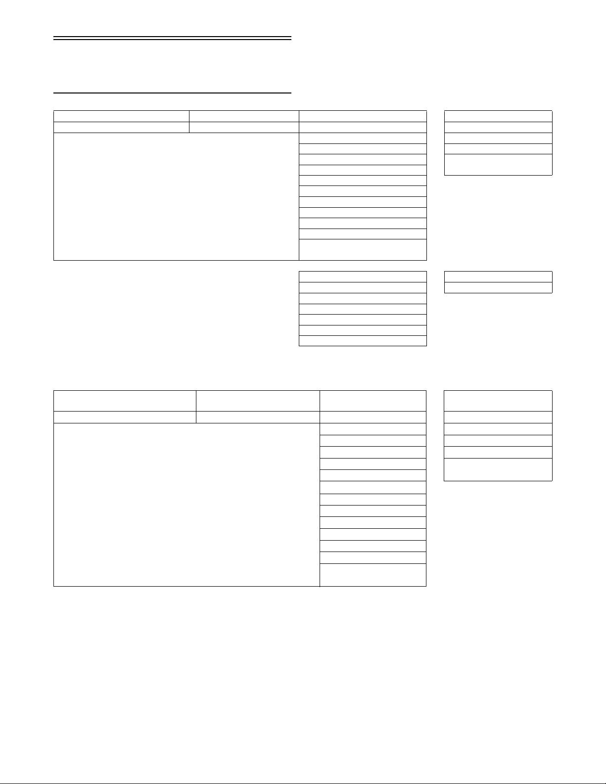
General Specifications
Torque Specifications
Chassis Length
(Cross Country)
Chassis Length (Sno Cross) 300 cm (118 in.)
Height (Cross Country) 126 cm (49.50 in.)
Height (Sno Cross) 120 cm (47.25 in.)
Width (Cross Country) 125-128 cm (49.25-50.25 in.)
Width (Sno Cross) 128-131 cm (50.50-51.50 in.)
Spindle Center-to-Center
Distance (Stance)
Dry Weight (approx) 204 kg (450 lb)
Gas Tank Capacity
(Cross Country)
Gas Tank Capacity (Sno Cross) 18.9 l (5.0 U.S. gal.)
Chain Case Lubricant Capacity 355 ml (15 fl oz)
Gasoline (Recommended) 91 Octane (minimum)
Pre-Mix Oil (32:1 Ratio) Arctic Cat Synthetic APV 2-Cycle Oil
Chain Case Lubricant Arctic Cat Synthetic Chain Lube
Suspension Grease All-Temperature
Brake Fluid High-Temp DOT 4
Taillight/Brakelight Bulb p/n 3303-849
Headlight Bulb p/n 0109-724
Cooling System Capacity 3.81 l (4.0 U.S. qt)
Starting System Manual Recoil
300 cm (118 in.)
106-109 cm (41.90-42.90 in.)
45.4 l (12.0 U.S. gal.)
Non-Oxygenated
Engine Specifications
Model AK60L3
Bore x Stroke 73.8 x 70 mm (2.906 x 2.755 in.)
Displacement 598.9 cc (36.54 cu. in.)
Cylinder/Head Volume Squish-Gap 1.396 mm (0.055 in.)
Cylinder/Head Volume Installed 24.81 cc (1.52 cu in.)
Cylinder/Head Volume Flat Plate 28.56 cc (1.74 cu in.)
Lighting Coil Output 13V/156W @ 3000 RPM
Ignition Type CDI/NOI
Ignition Timing Electronically
Controlled/Operator Adjustable
(Sno Cross)
Ignition Timing Electronically
Controlled/Operator Adjustable
(Cross Country)
Spark Plug Type NGK BR9EYA
Spark Plug Gap 0.7-0.8 mm (0.028-0.031 in.)
Compression Ratio 6.80:1
Piston Skirt/Cylinder Clearance
Range
Piston Ring End Gap Range 0.20-0.35 mm
Cylinder Truness Limit (max) 0.1 mm (0.004 in.)
Piston Pin Diameter Range 19.995-20.000 mm
Piston Pin Bore Diameter Range 20.002-20.010 mm
Connecting Rod Small End Bore
Diameter Range
Connecting Rod Radial Play Range 0.003-0.020 mm
Crankshaft Runout (t.i.r.) 0.05 mm (0.002 in.)
Crankshaft End Play Range 0.05-0.10 mm (0.002-0.004 in.)
25° BTDC @ 2000-3000 RPM
(4.123 mm or 0.162 in.)
25° BTDC @ 1500 RPM
(4.123 mm or 0.162 in.)
0.075-0.105 mm
0.0029-0.0041 in.
0.008-0.014 in.
0.7872-0.7874 in.
0.7875-0.7878 in.
25.003-25.011 mm
0.9844-0.9846 in.
0.0001-0.0008 in.
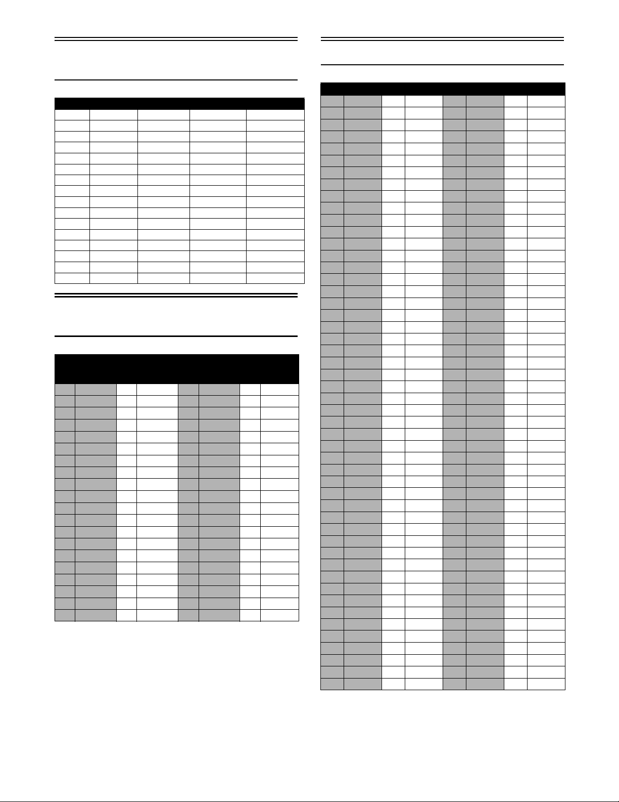
CHASSIS
Item Secured to
Rear Bumper
Steering Suppor t
Steering Suppor t
Rear Spar
Rear Spar
Side Spar - Right
Side Spar - Right
Side Spar
Side Spar - Right
Side Spar - Left
Spar, Upper Front
Spar, Upper Front
Tube, Support - Shock Tower
Toe Hook
Clutch Guard
Panel, Front Chassis
Panel, Front Chassis
Lower Frame - Weldment
Housing, A-Arm/Shock Mounting
Mounting Bracket - Upper A-Arm
Mounting Bracket - Upper A-Arm
Lower Frame - Weldment
Chassis
Chassis
Chassis 12
Chassis 12
Steering Support 23
Tunnel Support Bracket -
Rear Spar
Steering Support 34
Chassis 23
Chain Case 10
Housing, A-Arm/Shock
Mounting
Bracket, Exhaust Mount-
ing Spar
Chassis 12
Steering Support 34
Housing, A-Arm/Shock
Mounting
Housing, A-Arm/Shock
Mounting
Chassis 20
Chassis 5
Lower Frame - Weldment 12
Bellcrank 9
Chassis 20
Panel, Bellcrank/Shock
To we r
Panel, Bellcrank/Shock
To we r
Housing, A-Arm/Shock
Mounting
Heat Exchanger 25
Bracket, Spar Support 7
Seat, Hold-Down 20
Torque
ft-lb
23
12
12
34
20
12
12
12
DRIVE SYSTEM
Clutch, Drive**** Engine 51
Clutch, Driven* Shaft, Driven 20
CDI Plate, Air Silencer - Upper 8
Servomotor Mounting Bracket -
Voltage Regualtor Electrical Panel 5
Electrical Panel Steering Support 12
Timing Select Steering Support - Right 6
Chain Case Chassis 12
Chain Case Chassis 8
Brake Caliper Brake Caliper 25
Brake Hose Master Cylinder 25
Brake Hose Brake Caliper 25
Bridge Bolts Brake Caliper 60
Chain Case - Cover Chain Case 12
Bearing, Adapter Sleeve Lock Nut 58
Reservoir Cover Master Cylinder 12 in.-lb
Master Cylinder Clamp Master Cylinder 72 in.-lb
Brake Caliper Cover, Shield 8
Top Sprocket Driven Shaft 25
Servomotor
5
2

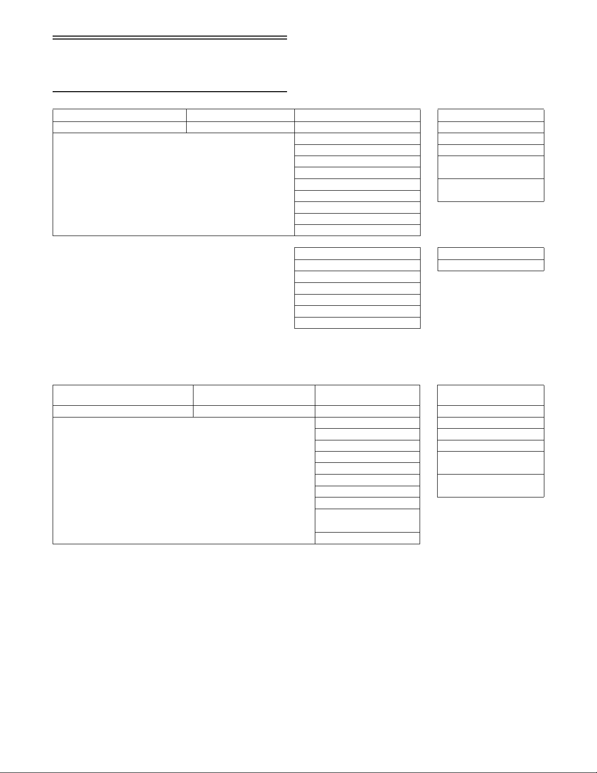
STEERING
Item Secured to
Post, Steering Bellcrank 43
Plate, Retaining - Bellcrank Bellcrank 20
Steering Support Mounting Block - Steering
Bellcrank Lower Frame - Bellcrank
Tie Rod, Spindle/Bellcrank Bellcrank 20
Tie Rod, Spindle/Bellcrank Spindle 40
Mounting Block - Throttle - Front Mounting Block - Throttle
Lever, Throttle Axle, Lever 18 in.-lb
Cap, Steering Block, Riser 15
Upper Arm Panel, Front Chassis 23
Upper Arm Spindle 45
Lower A-Arm - Front Lower Frame - Weldment 55
Lower A-Arm - Rear Lower Frame - Weldment 45
Lower A-Arm Spindle 45
Mounting Bracket - Sway Bar
Bushing (Cross Country)
Link, Sway Bar (Cross Country) Sway Bar, Formed 23
Link, Sway Bar (Cross Country) Lower A-Arm 23
Post
Mounting
- Rear
Panel, Front Chassis 8
Tor que
ft-lb
6
8
8
SUSPENSION
Suspension, Rear Axle, Front Arm 45
Suspension, Rear Axle, Offset Arm 45
Nosepiece Rail 80 in.-lb
Wearstrip Rail 50 in.-lb
Limiter Strap Front Arm 66 in.-lb
Limiter Strap Limiter Strap 66 in.-lb
Rail Crossbrace Axle 20
Rail Front Shock 40
Front Arm Rail 55
Front Shock Top Front Arm 50
Rear Arm Rail 20
Rear Arm Shock Idler Arm 40
Rear Arm Idler Arm 40
Rear Shock Link Rear Shock Axle 40
Spring Slide Rail 20
Offset Arm Idler Arm 20
Rear Wheel Axle (Left***, Right*) Axle Nut 60
Shock Pivot Rail 40
Rail Coupling Block 80 in.-lb
Rail Brace Rail 10
Rail Brace Rail 20
Rail Brace Axle, Crossbrace 20
Rail Axle, Crossbrace - Rear
Track Adjuster Rail 10
Rail Brace Pad, Shock 4
Arm
40
ENGINE
Item Secured to
Cylinder Head/Cover Cylinder (2 Steps) 20-25 ft-
Cylinder Crankcase (3 Steps) 14-40 ft-
Thermostat Cap Crankcase 96 in.-lb
Flywheel** Crankcase 50 ft-lb
Exhaust Manifold Cylinder 96 in.-lb
Crankcase (6 mm)
(10 mm)
Spark Plug Cylinder 19 ft-lb
Water Pump Impeller* Crankcase 96 in.-lb
Coolant Temperature Sensor Crankcase 18 ft-lb
APV Assemblies* Cylinder 96 in.-lb
Recoil Starter Crankcase 96 in.-lb
Coolant Hose - Engine/Coolant Tank Engine 11 in.-lb
Coolant Hose - Engine/Coolant Tank Coolant Bottle Bypass 11 in.-lb
Coolant Hose - Engine/Front
Exchanger
Tank, Coolant Coolant Bottle Bypass 30 in.-lb
Coolant Hose - Tunnel Exchanger/
coolant Tank
Carberator Boot Flange 5.5 in.-lb
Hose, Throttle Body/Water Pump Both Ends 14 in.-lb
Sensor, Exhaust Temperature Chamber, Expansion 34
Manifold, Exhaust Engine Studs 7
Intake Manifold/Reed Cage Engine 8
Servo Cable Plate Engine 44 in.-lb
Engine Mount Engine Mount - Front 12
Engine Mount - Front Engine 25
Engine Mount - Front Chassis 35
Mounting Plate - MAG Engine 25
Mounting Plate - PTO Nut Plate 20
Mounting Plate - PTO Hub, Bearing Housing 12
Mounting Plate - PTO Engine 25
Lower Mount - Rear Chassis 12
Lower Mount - Rear Chassis 7
Water Pump Engine 7
Crankcase
(2 Steps)
Front Exchanger 11 in.-lb
Exchanger/bypass 11 in.-lb
Tor que
ft-lb
lb
lb
96 in.-lb
13-37 ftlb
MISCELLANEOUS
Taillight Lens Taillight Bracket 4
Pump, Fuel Plate, Air Silencer -
Mounting Bracket - Air Silencer Chassis 8
Mounting Bracket - Air Silencer Silencer, Air - Front
Intake Baffle Plate, Intake 8
Speedometer/Tachometer (Cross
Country)
Snowflap Restraint (Sno Cross) Tunnel 8
Lower
Bumper
Center Gauge Bracket 8 in.-lb
8
8
*w//Blue Loctite #243
** w/Red Loctite #271
***w/Green Loctite #620
****w/oil
3
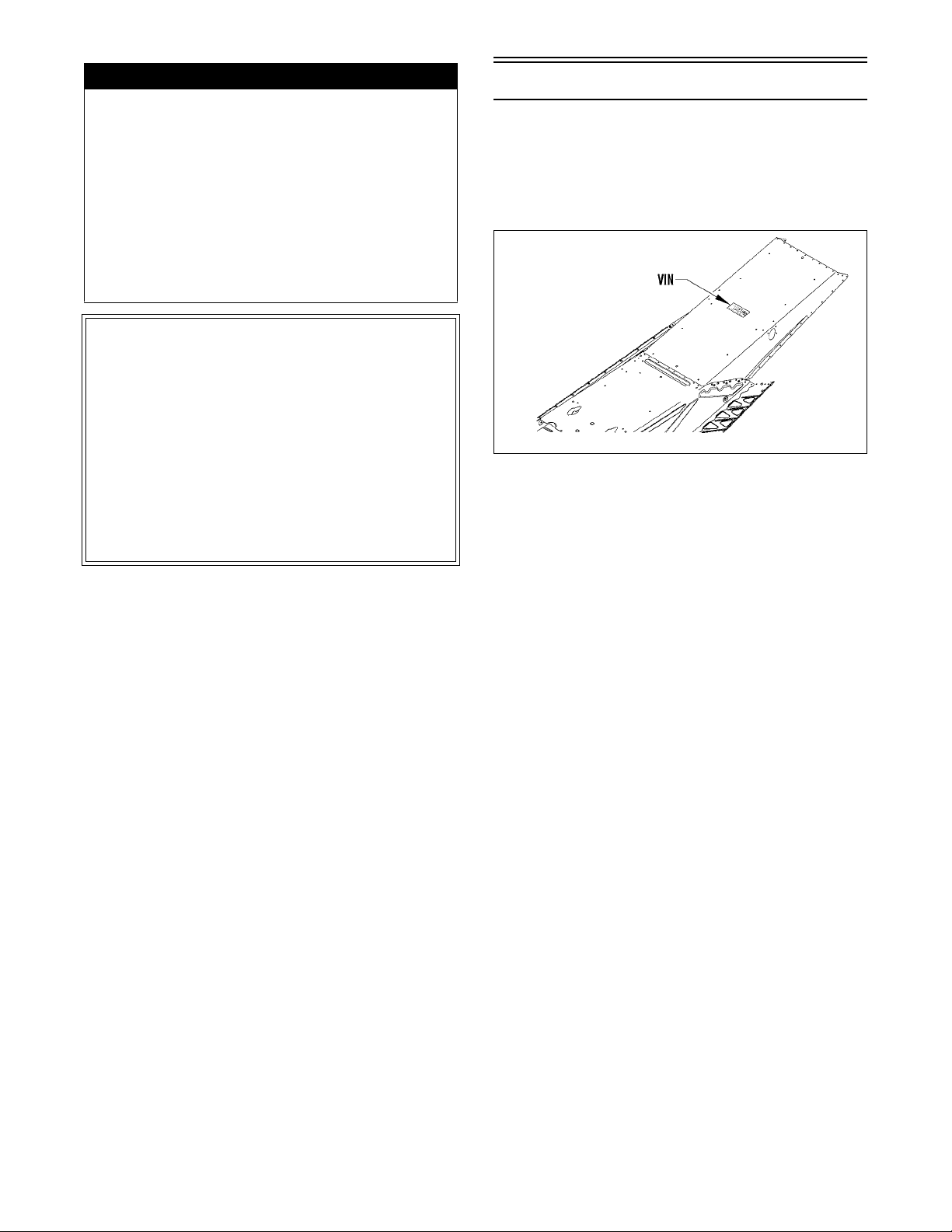
Engine Torque Patterns
0744-096
0738-220
Torque Conversions
(ft-lb/N-m)
ft-lb N-m ft-lb N-m ft-lb N-m ft-lb N-m
1 1.4 26 35.4 51 69.4 76 103.4
2 2.7 27 36.7 52 70.7 77 104.7
3 4.1 28 38.1 53 72.1 78 106.1
4 5.4 29 39.4 54 73.4 79 107.4
5 6.8 30 40.8 55 74.8 80 108.8
6 8.2 31 42.2 56 76.2 81 110.2
7 9.5 32 43.5 57 77.5 82 111.5
8 10.9 33 44.9 58 78.9 83 112.9
9 12.2 34 46.2 59 80.2 84 114.2
10 13.6 35 47.6 60 81.6 85 115.6
11 15 36 49 61 83 86 117
12 16.3 37 50.3 62 84.3 87 118.3
13 17.7 38 51.7 63 85.7 88 119.7
14 19 39 53 64 87 89 121
15 20.4 40 54.4 65 88.4 90 122.4
16 21.8 41 55.8 66 89.8 91 123.8
17 23.1 42 57.1 67 91.1 92 125.1
18 24.5 43 58.5 68 92.5 93 126.5
19 25.8 44 59.8 69 93.8 94 127.8
20 27.2 45 61.2 70 95.2 95 129.2
21 28.6 46 62.6 71 96.6 96 130.6
22 29.9 47 63.9 72 97.9 97 131.9
23 31.3 48 65.3 73 99.3 98 133.3
24 32.6 49 66.6 74 100.6 99 134.6
25 34 50 68 75 102 100 136
738-202A
Tightening Torque
(General Bolts)
Type of Bolt
(Grade 8.8) 5 60 in.-lb
(Grade 10.9) 6 12 ft-lb
Thread
Diameter A
(mm)
6 96 in.-lb
8 20 ft-lb
10 40 ft-lb
12 65 ft-lb
8 28 ft-lb
10 50 ft-lb
12 95 ft-lb
Tightening
Torq ue
4

Electrical Specifications
NOTE: The ignition system is a Normally Open
Ignition (NOI).
Component Voltage/
Resistance Chart - Water
Temperature
Description
Ignition Coil
Primary
Secondary
DC Power Coil 0.71-1.07 ohms red/yellow yellow/red
Lighting Coil 0.12-0.18 ohm yellow yellow
Ignition Timing
Sensor
Spark-Plug Cap 4000-6000 ohms cap end cap end
Description Test Value + Test Connections -
Voltage Regulator 11-14 AC Volts yellow brown
Regulator/Rectifier 11.2-16.8 DC Volts
Condenser 11.6-17.4 DC Volts
High Temperature
Sensor
Tether Switch Less than 1 ohm
Resistance Test
Test Value
0.27-0.41 ohm
6800-10,200 ohms
148-222 ohms green/white brown/green
(@ 2000 RPM)
(@ 2000 RPM)
305 ohms + (water
temperature at or
above 176°F)
203 ohms +
(water temperature
at or above 200°F)
(tether cap removed)
+ Test Connections -
orange
high tension
wire
red/blue brown/yellow
red brown
terminal #1 terminal #2
terminal #1 terminal #2
terminal terminal
black
high tension
wire
Temperature Vo lt s Ohms Temperature Vo lts Ohms
110 °C 230 °F 0.115 129 28 °C 82 °F 1.377 1800
108 °C 226 °F 0.129 137 26 °C 79 °F 1.459 1950
106 °C 223 °F 0.143 145 24 °C 75 °F 1.541 2100
104 °C 219 °F 0.157 153 22 °C 72 °F 1.623 2250
102 °C 216 °F 0.171 161 20 °C 68 °F 1.705 2400
100 °C 212 °F 0.185 169 18 °C 64 °F 1.806 2670
98 °C 208 °F 0.192 180 16 °C 61 °F 1.907 2940
96 °C 205 °F 0.199 191 14 °C 57 °F 2.008 3210
94 °C 201 °F 0.206 202 12 °C 54 °F 2.109 3480
92 °C 198 °F 0.213 213 10 °C 50 °F 2.210 3750
90 °C 194 °F 0.220 224 8 °C 46 °F 2.327 4170
88 °C 190 °F 0.235 240 6 °C 43 °F 2.444 4590
86 °C 187 °F 0.250 256 4 °C 39 °F 2.561 5010
84 °C 183 °F 0.265 273 2 °C 36 °F 2.678 5430
82 °C 180 °F 0.280 289 0 °C 32 °F 2.795 5850
80 °C 176 °F 0.295 305 -2 °C 28 °F 2.901 6510
78 °C 172 °F 0.317 327 -4 °C 25 °F 3.007 7170
76 °C 169 °F 0.339 349 -6 °C 21 °F 3.113 7830
74 °C 165 °F 0.361 371 -8 °C 18 °F 3.219 8490
72 °C 162 °F 0.383 393 -10 °C 14 °F 3.325 9150
70 °C 158 °F 0.405 415 -12 °C 10 °F 3.421 9422
68 °C 154 °F 0.438 445 -14 °C 7 °F 3.517 9694
66 °C 151 °F 0.471 475 -16 °C 3 °F 3.613 9966
64 °C 147 °F 0.504 505 -18 °C -0.4 °F 3.709 10238
62 °C 144 °F 0.537 535 -20 °C -4 °F 3.805 10510
60 °C 140 °F 0.570 565 -22 °C -8 °F 3.885 13688
58 °C 136 °F 0.598 609 -24 °C -11 °F 3.965 16866
56 °C 133 °F 0.626 653 -26 °C -15 °F 4.045 20044
54 °C 129 °F 0.654 697 -28 °C -18 °F 4.125 23222
52 °C 126 °F 0.682 741 -30 °C -22 °F 4.205 26400
50 °C 122 °F 0.710 785 -32 °C -26 °F 4.267 30520
48 °C 118 °F 0.759 849 -34 °C -29 °F 4.329 34640
46 °C 115 °F 0.808 913 -36 °C -32 °F 4.391 38760
44 °C 111 °F 0.857 977 -38 °C -36 °F 4.453 42880
42 °C 108 °F 0.906 1041 -40 °C -40 °F 4.515 47000
40 °C 104 °F 0.955 1105 -42 °C -44 °F 4.553 55100
38 °C 100 °F 1.023 1214 -44 °C -47 °F 4.591 63200
36 °C 97 °F 1.091 1323 -46 °C -51 °F 4.629 71300
34 °C 93 °F 1.159 1432 -48 °C -54 °F 4.667 79400
32 °C 90 °F 1.227 1541 -50 °C -58 °F 4.705 87500
30 °C 86 °F 1.295 1650
5
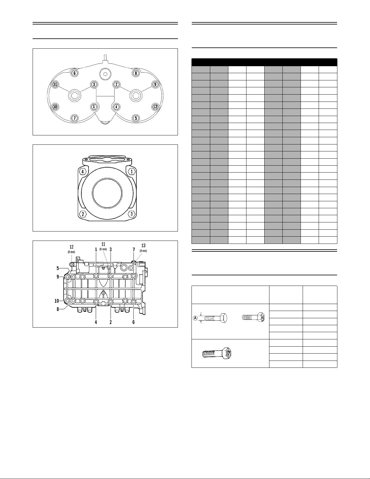
Crankshaft Runout/
Repair Specifications
For those who have crankshaft work sent out to
another shop, it is advisable to provide them with this
information.
To use the specifications, first refer to the drawing;
then find the letter which indicates the specification
and refer to the chart below the illustration. Specifications are called out in both millimeters and inches.
NOTE: We have given the proper location for
728-144A
checking crankshaft runout as the very edge of the
straight portion of the shaft where the oil seal makes
contact. From the illustration, note that Arctic Cat
has called out three check points: at either end, out
on the taper as shown, and also on the center bearing race. The crankshaft is still supported on the
outer bearings using V blocks. The maximum runout
shouldn’t exceed 0.05 mm (0.002 in.).
NOTE: Measure in from the shaft end the specified amount when checking runout at points D and
F. When checking runout in the center, place indicator on center of bearing as shown at point E.
Maximum runout at any of the 3 measuring points
is ±0.05 mm (0.002 in.).
Bore X StrokeA ± 0.15
73.8 x 70 mm
(2.906 x 2.756”)
(± 0.006)
119.7 mm
(4.712”)
B
± 0.15
(± 0.006)
64 mm
(2.519”)
C
± 0.4
( ± 0.015)
118 mm
(4.645”)30(1.181)
G
Point (± .002)
D 5
(0.196)
Runout
D and F
(0.196)
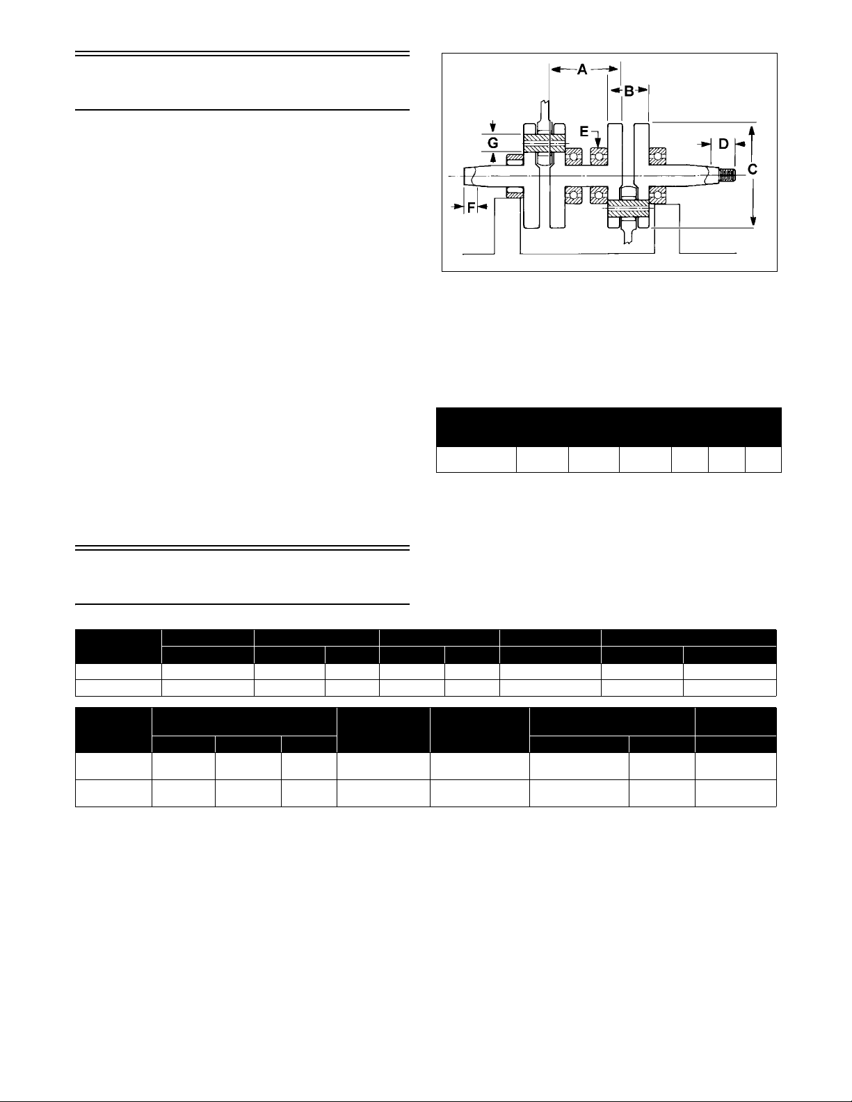
Drive System
Specifications
MODEL
Sno Cross 0746-264 0646-216 Yellow 0746-830 60.0 0726-329 0648-792 Black/Orange
Cross Country 0746-265 0646-216 Yellow 0746-826 64.0 0726-331 0648-792 Black/Orange
DRIVE CLUTCH DRIVE SPRING CAM ARM DRIVEN CLUTCH DRIVEN SPRING
P/N P/N COLOR P/N GRAMS P/N SPRING COLOR
F 5
MODEL
Sno Cross 0627-086 48.15 in.
Cross Country 0627-086 48.15 in.
* ± 0.188 in. (4.78 mm)
DRIVE BELT
P/N Length* Width* PITCH P/N DEGREE
(1223 mm)
(1223 mm)
1.45 in.
(36.8 mm)
1.45 in.
(36.8 mm)
ENGAGEMENT/
MAXIMUM RPM
4900-5200/
8300-8500
4400-4600/
8300-8500
NOTE: For optional drive system components,
refer to the Optional Components chart on the following page.
6
GEAR
RATIO
21/49
(13/13 wide)
23 (13 wide)/
40 (13 wide)
CHAIN
90
(13 wide)
90 (13 wide) 2602-370 44/42
2602-370 70-44-32
TORQUE
BRACKET
68-42-32

Drive Clutch/Driven
Clutch Optional
Components
Drive Clutch
Spring Color Spring Rate
0646-400 Blue
0646-684 Black 158/290
0646-410 Blue 165/305
0646-035 Orange/Black 143/286
Driven Clutch
Torq ue
Bracket
0648-779* 58-46-36/
0648-775* 52-42-46/
0648-773* 70-44-32/
0648-710 70-50-46/
0648-737 70-44-32/
0648-719 68-42-34/
0648-789* 68-48-36/
0648-791* 48-44-36/
0648-823 70-44-32/
0648-809 44/42
0648-805 40/38
0648-822 70-44-32/70-46-32
Degree Spring Color
58-48-36
52-44-46
68-48-46
68-48-46
68-48-46
68-44-32
64-48-41
48-42-36
68-42-32
(Titanium)
0648-749 Black/White 160/260
0648-702 Red/Black 140/240
0648-784 Black 155/222
0648-790 Black/
0648-792 Black/Orange 180/280
———
———
———
165/310
Light Blue
Spring
Rate
180/260
*Lightweight driven clutch only.
Drive Clutch Spring Chart
Drive Clutch Cam Arms
(w/Set Screw)
ARCTIC CAT DRIVE CLUTCH CAM ARMS
p/n Grams p/n Grams
0746-661 52.0 0746-712 77.0
0746-662 52.0 0746-713 48.0
0746-663 52.0 0746-715 77.0
0746-664 52.0 0746-716 73.0
0746-666 55.0 0746-742 83.5
0746-668 55.0 0746-744 50.0
0746-669 60.0 0746-748 46.0
0746-670 65.0 0746-749 65.0
0746-671 70.0 0746-771 44.0
0746-672 75.0 0746-772 42.0
0746-673 80.0 0746-773 85.0
0746-676 70.0 0746-786 63.0
0746-678 55.0 0746-787 44.0
0746-687 57.0 0746-788 47.5
0746-689 69.0 0746-789 42.0
0746-690 47.0 0746-791 60.0
0746-691 44.0 0746-792 47.0
0746-692 50.0 0746-793 63.0
0746-694 63.0 0746-814 83.0
0746-695 67.0 0746-821 82.0
0746-696 63.0 0746-822 71.5
0746-698 64.0 0746-824 66.0
0746-699 66.0 0746-825 50.0
0746-701 49.0 0746-826 64.0*
0746-702 57.5 0746-830 60.0
0746-703 68.0
0746-704 51.0
0746-708 51.0
0746-710 72.0
* Notched Cam Arm
ARCTIC CAT DRIVE CLUTCH SPRING CHART
p/n Rate @ 2 9/16 in. Rate @ 1 5/16 in. Color
LIGHT 0646-148 53 lb 224 lb Blue
0646-150 72 lb 188 lb Silver
0646-149 74 lb 228 lb Red
0646-376 75 lb 275 lb Gold
0646-147 114 lb 267 lb Yellow/Green
0646-373* 114 lb 267 lb Yellow/Green
0646-155 121 lb 240 lb Purple
0646-229 122 lb 285 lb Yellow/White
0646-379* 122 lb 285 lb Yellow/White
0646-035 143 lb 286 lb Orange/Black
0646-447* 143 lb 286 lb Pink/White
0646-248 143 lb 290 lb Orange/White
0646-367 143 lb 250 lb Black
0646-435 143 lb 290 lb Orange
Stripe
0646-684 158 lb 290 lb Black
HEAVY 0646-216 170 lb 330 lb Yellow
* Titanium
7
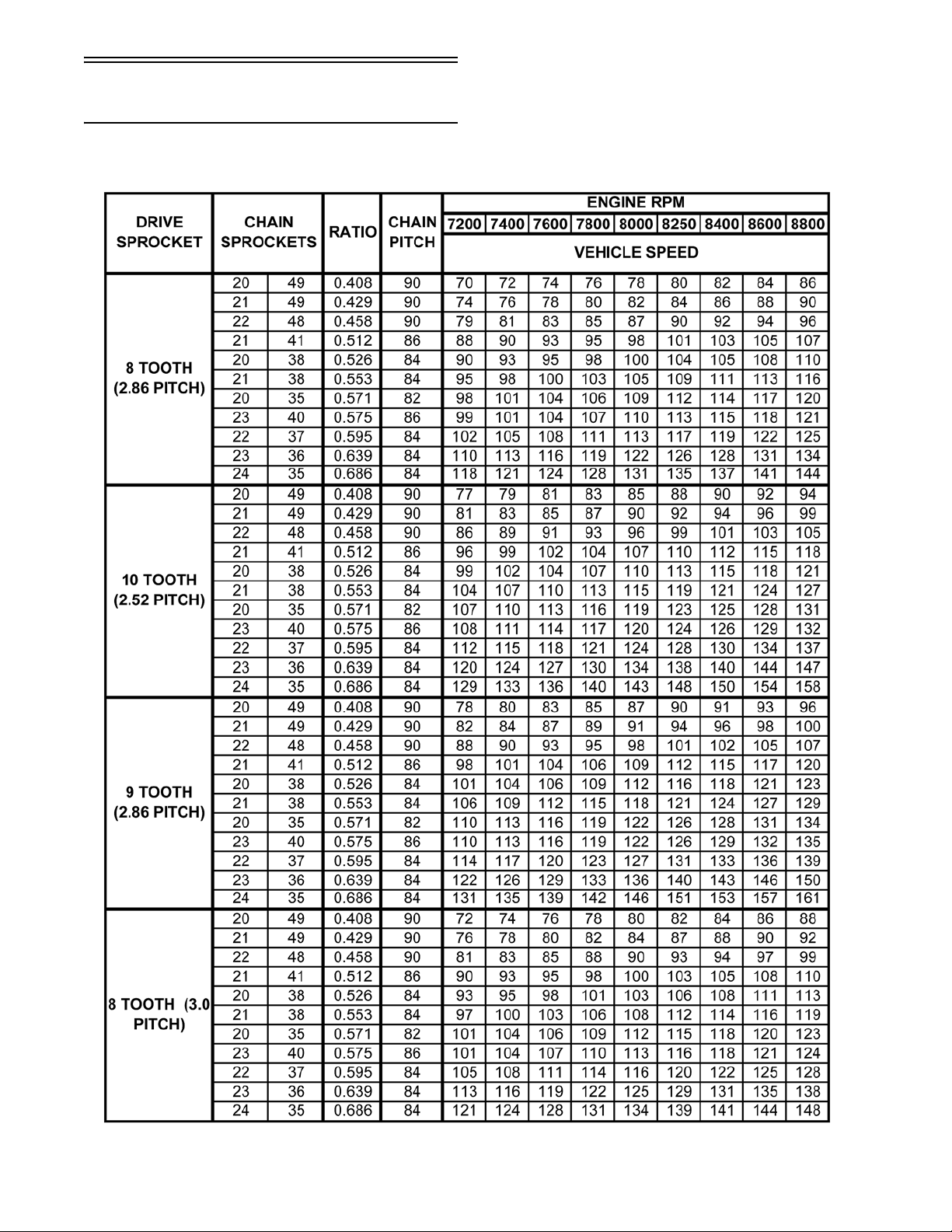
Chain Case Performance
Calibrations
NOTE: The following table should be used as a guide only.
NOTE: The above gearing options are combinations which allow acceptable chain tension. Any other
combinations will not allow acceptable chain tension.
8
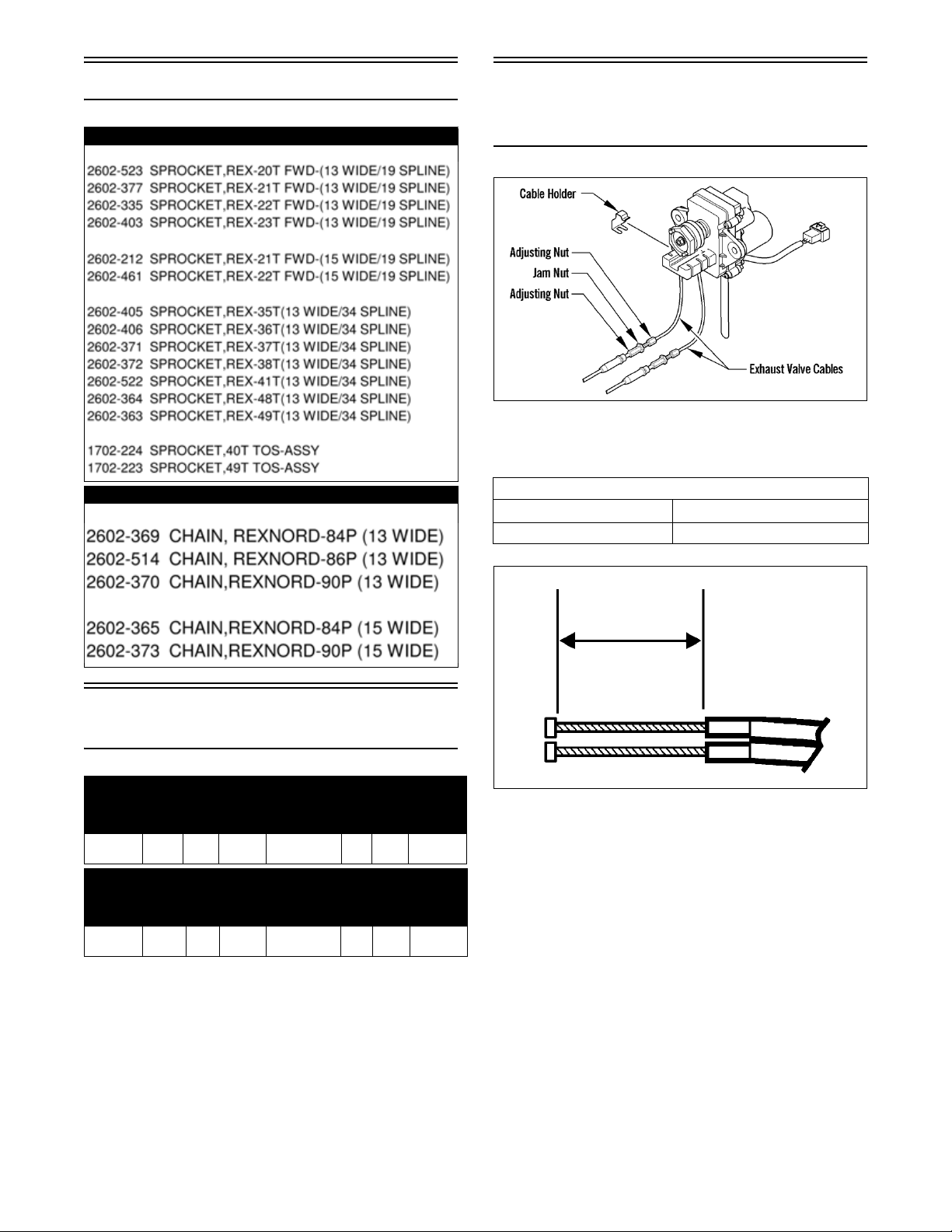
Chains and Sprockets
Part Number Sprocket
Arctic Power Valve
(APV) System
Specifications
NOTE: The servo will activate once (clean cycle)
at 2500 RPM. If the servo cycles three times, cable
length adjustment or valve inspection is required.
Model Ty pe
Sno Cross
Model Type
Cross
Country
TM-40 400 Q0
TM-40 490 Q0
Part Number Chain
Carburetor
Specifications
Main
Jet
Main
Jet
Needle
Jet
(825)
Needle
Jet
(825)
Jet
Needle
9DFH12-54-3 50 2.5 1.25
Jet Needle
9DFH12-54-3
Pilot
Jet
Pilot
Jet
45 2.5 1.25
Cut
Away
Cut
Away
Pilot Air
Screw
(Turns
Out)
Pilot Air
Screw
(Turns
Out)
APV CABLE LENGTH
ENGINE CENTER ± 1 mm (0.039 in.)
600 cc 36.5 mm (1.437 in.)
0735-516
9
Mikuni Tuning
Components
MAIN JETS AVAILABLE
JET P/N JET P/N
120 6505-270 420 6505-125
130 6505-216 430 6505-146
140 6505-217 440 6505-126
150 6505-168 450 6505-147
160 6505-064 460 6505-127
170 6505-065 470 6505-148
180 6505-056 480 6505-149
190 6505-066 490 6505-150
200 6505-144 500 6505-151
210 6505-145 510N 6506-378
220 6505-137 520 6505-530
230 6505-067 520N 6506-379
240 6505-079 530 6505-170
250 6505-068 530N 6506-380
260 6505-017 540 6505-531
270 6505-069 540N 6506-381
280 6505-080 550N 6506-382
290 6505-123 560 6505-172
300 6505-128 560N 6506-383
310 6505-136 580 6505-211
320 6505-074 590 6505-173
330 6505-070 600 6505-532
340 6505-076 620 6505-174
350 6505-071 640 6505-533
360 6505-038 650 6505-534
370 6505-072 660 6505-535
380 6505-077 680 6505-169
390 6505-078 700 6505-536
400 6505-124 710 6505-537
410 6505-212 720 6505-538
THROTTLE VALVES AVAILABLE
SLIDE P/N
2.0 6506-119
3.0 6506-120
3.0 6506-232*
3.5 6506-210
2.5 6506-273
* High Altitude
JET NEEDLES AVAILABLE
JET NEEDLE P/N
9CFH1-56 6506-116
9DH2-59 6506-110
9DH5-61 6506-114
9DEH1-55 6506-118
9DEH2-57 6506-115
9EGY01-57 6506-192
9EHO9 6506-173
9EH2-57 6506-111
9EH6-60 6506-117
9EJ1-60 6506-384
9EH7-62 6506-113
9DFH2-58 6506-200
9DFH2-59 6506-201
9DFH3-56 6506-186
9DEH3 6506-182
9DFH1-56 6506-221
9DFH12-54 6506-421
9DFH9-59 6506-304
9EH6-59 6506-228
9DH9-54 6506-272
9EH6-58 6506-290
9DFH4-60 6506-260
9EFH9-60 6506-374
INLET NEEDLE ASSEMBLIES AVAILABLE
SEAT DIA. CARB. SIZE (mm) P/N
1.5 mm (Steel) 38 6506-121
1.8 mm (Steel) 38 6505-144
PILOT JETS AVAILABLE
JET NO. P/N JET NO. P/N
17.5 6505-218 35 6505-029
20 6505-138 40 6505-047
22.5 6505-310 45 6505-278
25 6505-075 50 6505-262
27.5 6505-503 52.5 6505-261
30 6505-073 55 6505-255
10
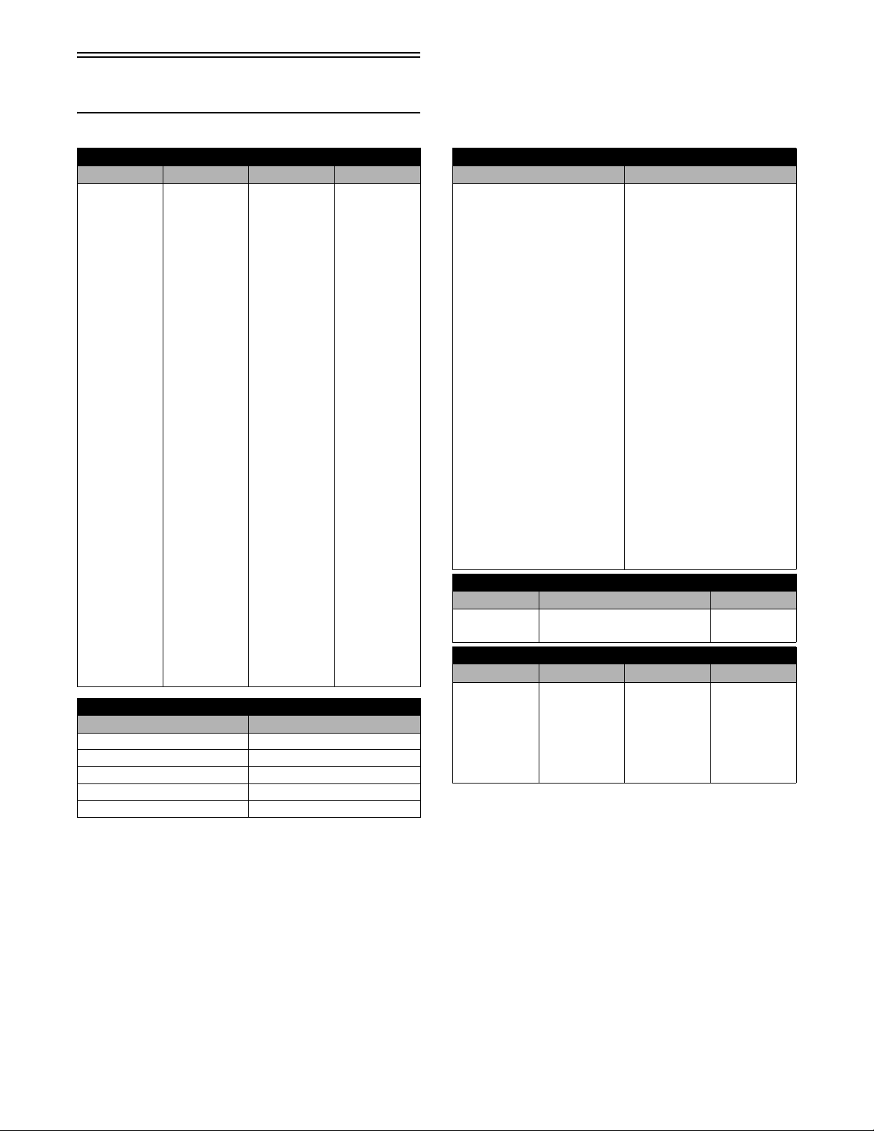
Major Tuning
Components
To assist in selecting two major tuning components of
the TM-style carburetor, listed below are pilot jets and
throttle valves (slides) according to their size.
PILOT JETS
Lean
Rich
12.5
15
17.5
20
22.5
25
27.5
30
32.5
35
37.5
40
45
50
55
60
65
70
Letter Angle Letter Angle
A 0°15’ I 2°15’
B 0°30’ J 2°30’
C 0°45’ K 2°45’
D1°0’L3°0’
E 1°15’ M 3°15’
F 1°30’ N 3°30’
G 1°45’ O 3°45’
H2°0’P4°0’
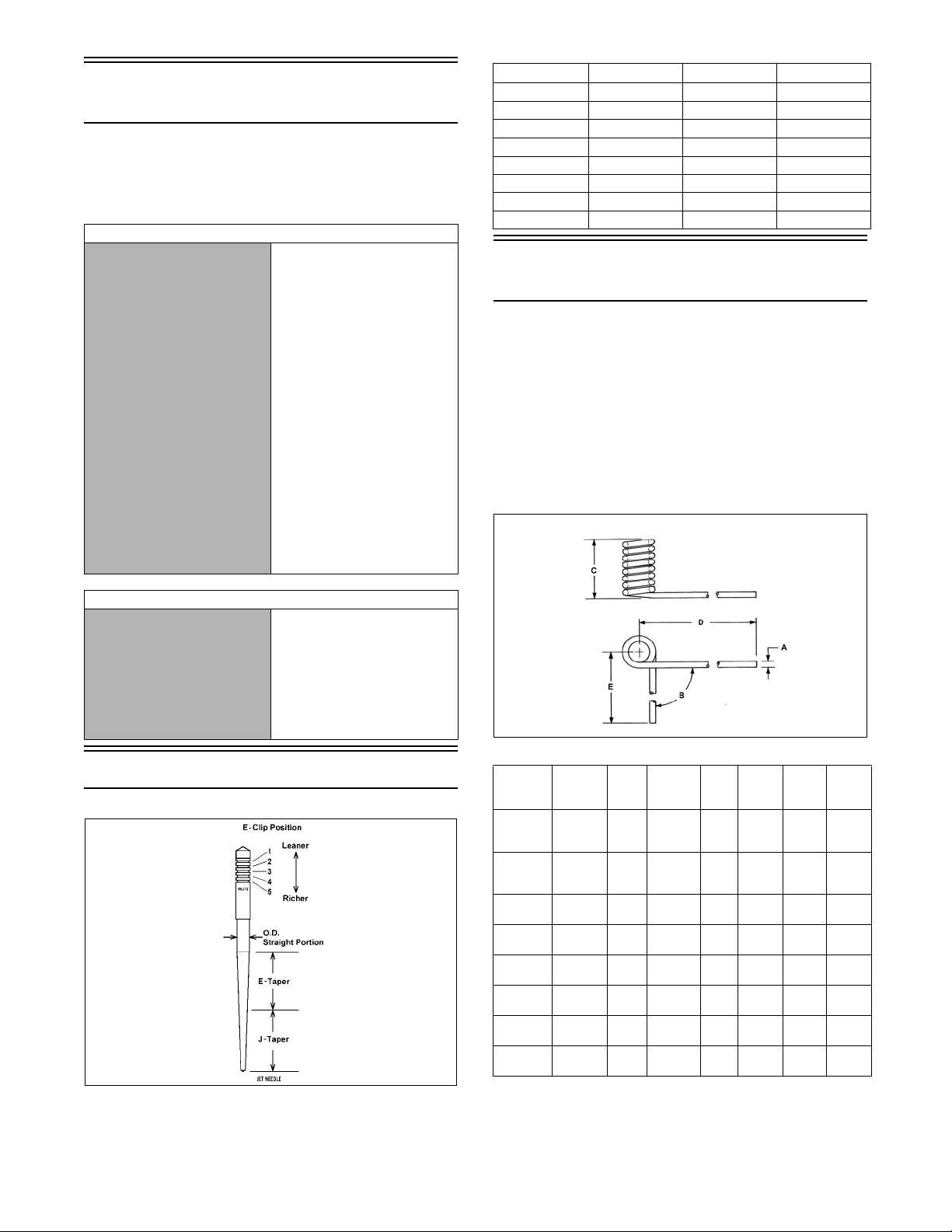
Rear Spring Selection
Chart
Below is a list of rear suspension springs and specifications. This chart was compiled to assist technicians
in fine-tuning the Arctic Cat rear suspension when the
original springs are not optimum for the conditions
and a softer or firmer ride is desired.
A longer spring in areas (D) and (E) can be selected if
cut off to match the original spring. The replacement
spring must match the original spring in areas (C), (D),
and (E).
THROTTLE VALVES (SLIDES)
Lean
Rich
4.0
3.5
3.0
2.5
2.0
1.5
1.0
Jet Needle Taper Angles
0734-462
0730-218
P/N
1704-382/
383
(Light)
1704-384/
385
(Heavy)
1704-916/
917
2704-224/
225
1704-576/
577
2704-384/
385
2704-380/
381*
2704-382/
383**
Wire
Diameter
(A)
.359 90° 5.75 3.00 15.62 4.60 17
.375 90° 5.75 3.00 15.62 4.60 20
.405 120° 5.90 3.20 15.62 4.70 24
.437 105° 6.80 3.75 15.62 4.70 27.3
.405 90° 6.75 3.65 18.50 5.50 18.5
.405 115° 6.80 3.65 15.62 4.70 18.9
.437 92° 6.75 3.75 15.62 4.70 27.4
.405 89° 6.75 3.65 15.62 4.70 18.9
Angle
(B)
Number
of
Coils
Coil
Width
(C)
Length
(D)
Length
(E)
Degree
(In lb)
* Production (Sno Cross) **(Production (Cross Country)
NOTE: The wire diameter and length of the spring
have a large influence over the valving of the
shocks.
11
Installed Spring Rate
Chart
Rebuildable Shock Tools
Required
Suspension Fully
P/N
1704-382/383 1360 1700
1704-384/385 1600 2001
1704-916/917 480 960
2704-224/225 1350 1890
1704-576/577 1480 1850
2704-380/381 2082 2630
2704-382/383 1550 1928
2704-384/385 567 945
P/N
1704-382/383 3740 4080
1704-384/385 4411 4812
1704-916/917 3840 4320
2704-224/225 5130 5670
1704-576/577 4070 4440
2704-380/381 5918 6466
2704-382/383 4196 4574
2704-384/385 3213 3591
Extended
(In lb - Adjuster
Set 1 & 1)
Suspension Fully
Collapsed
(In lb - Adjuster
Set 1 & 1)
Suspension Fully
Extended
(In lb - Adjuster
Set 3 & 3)
Suspension Fully
Collapsed
(In lb - Adjuster
Set 3 & 3)
Front Suspension
Sway Bar
P/N Tool
0744-020 Inflation Needle
0644-486 Gas Shock Retaining Blocks
0644-544 Replacement Needle
0644-169 Piston Location Tool
0644-151 Nitrogen Regulator
0644-268 Bearing Cap Seal Protector
0644-403 Bearing Cap Seal Protector (1/2-in. O.D. x 3/8 in. I.D.)
0644-404 Bearing Cap Seal Protector (5/8-in. O.D. x 3/8 in. I.D.)
0644-542 Bearing Cap Seal Protector (5/8 in. O.D. x 1/2 in. I.D.)
0644-543 Gas Shock Shaft Clamping Tool
0644-350 Floating Piston Location Gauge
0644-539 Inflation Needle Replacement Tip
0744-072 Float Shock Spanner Wrench
0644-584 Air Sleeve Bushing Installation Tool
0644-585 Air Sleeve Bushing Installation Tool
0644-456 Bullet Air Sleeve Bushing Installation Tool
Sway Bar p/n Bushing p/n Description
2703-615 2603-944/945 (inc.) 11.1 mm diameter
2703-793 2603-946/947 (inc.) 12.7 mm diameter
NOTE: Sway Bar Mounting Kit (p/n 6639-001).
12
Valve Stacks/
Specifications
(Sno Cross)
Part Number Description Compression (Piston Side) Rebound (Piston Side)
3703-062/063 Ski Shock 1.300 x 0.006 in. 1.100 x 0.008 in.
Extended Length: 19.10 in. Rebuild Kit - p/n 2603-929 1.300 x 0.008 in. 0.600 x 0.004 in.
Collapsed Length: 13.30 in. Rebuild Kit - p/n 3604-539
Stroke: 5.80 in. 1.100 x 0.012 (Center) 1.125 x 0.080 in.
Piston Orifice: None Piston Depth: 2.50 in.
(Reservoir)
CD Knob @ 8; RB Knob @ 2. Eyelets tightened to 3.9 kg-m (28 ft-lb). Piston nut tightened to 3.0 kg-m (22 ft-lb).
Tighten the shaft nut to 3.0 kg-m (22 ft-lb). Shocks charged at 350 psi (nitrogen)/150/275 psi (air).
Green Loctite #620 on shock eyelet threads.
Part Number Description
2704-311 Front Arm Shock* 1.300 x 0.012 in. 1.100 x 0.008 in.
Extended Length: 12.10 in. Rebuild Kit - p/n 3604-538 1.300 x 0.012 in. 0.600 x 0.004 in.
Collapsed Length: 8.30 in. Rebuild Kit - p/n 3604-539 1.300 x 0.012 in. 0.700 x 0.004 in.
(Reservoir) 1.300 x 0.012 in. 0.800 x 0.004 in.
Stroke: 3.80 in. 1.300 x 0.015 in.
Piston Orifice: None Piston Depth: 1.80 in.
* Compression (Initial Setting): Full Open. Eyelets tightened to 3.9 kg-m (28 ft-lb). Piston nut tightened to 3.0 kg-m (22 ft-lb). Tighten
shaft nut to 3.9 kg-m (28 ft-lb). Shock charged at 350 psi. Green Loctite #620 on shock eyelet threads.
1.300 x 0.010 in. 0.800 x 0.006 in.
1.250 x 0.015 (Ring)
1.300 x 0.010 in.
0.800 x 0.004 in.
1.300 x 0.012 in.
1.300 x 0.012 in.
1.250 x 0.010 in.
1.000 x 0.015 in.
1.125 x 0.093 in.
Top out washer
Ground
Compression (CD Piston) Rebound (CD Piston)
0.700 x 0.010 in. 0.700 x 0.008 in.
0.700 x 0.010 in.
0.600 x 0.010 in.
0.500 x 0.006 in.
0.400 x 0.020 in. (BU)
0.400 x 0.020 in. (BU)
Compression
(Piston Side)
1.300 x 0.012 in. 1.125 x 0.080 in.
1.300 x 0.015 in.
1.100 x 0.008 (Center)
1.250 x 0.012 (Ring)
1.300 x 0.015 in.
0.900 x 0.008 in.
0.800 x 0.006 in.
1.300 x 0.008 in.
1.125 x 0.093 in.
Top out washer
Rebound
(Piston Side)
Ground
13

Part Number Description
2704-312 Rear Arm Shock** 1.600 x 0.008 in. 1.425 x 0.010 in.
Extended Length: 14.51 in. Rebuild Kit - p/n 2603-013 1.600 x 0.010 in. 1.100 x 0.004 in.
Collapsed Length: 10.08 in. Rebuild Kit - p/n 3604-539 1.425 x 0.012 (Center) 1.400 x 0.093 in.
Stroke: 4.43 in. (Reservoir)
CD Piston
Compression Rebound 1.600 x 0.012 in.
0.700 x 0.010 in. 0.700 x 0.008 in. 1.100 x 0.004 in.
0.700 x 0.010 in. 1.600 x 0.012 in.
0.400 x 0.020 in. 1.600 x 0.012 in.
0.400 x 0.020 in. 1.600 x 0.012 in.
Piston Orifice: None
Piston Depth: 2.40 in.
Compression
(Piston Side)
1.600 x 0.15 (Ring) 0.750 x 0.100 in.
1.600 x 0.012 in.
1.600 x 0.012 in.
1.425 x 0.006 in.
1.250 x 0.006 in.
1.100 x 0.006 in.
0.950 x 0.008 in.
1.570 x 0.128 in.
Top out washer
Rebound
(Piston Side)
Ground
Backup
** Compression (Initial Setting): Full Open. Rebound (Initial Setting): 12 Clicks Counterclockwise.
Shock charged at 350 psi. Green Loctite #620 on shock eyelet threads.
Eyelets tightened to 3.9 kg-m (28 ft-lb). Piston nut tightened to 3.0 kg-m (22 ft-lb).
Tighten the shaft nut to 3.9 kg-m (28 ft-lb).
14
Valve Stacks/
Specifications
(Cross Country)
Part Number Description Compression (Piston Side) Rebound (Piston Side)
3703-064/065 Ski Shock 1.300 x 0.006 in. 1.100 x 0.008 in.
Extended Length: 18.90 in. Rebuild Kit - p/n 2603-929 1.300 x 0.008 in. 0.600 x 0.004 in.
Collapsed Length: 13.30 in. Rebuild Kit - p/n 3604-539 0.900 x 0.006 in. 0.800 x 0.006 in.
Stroke: 5.60 in. (Reservoir) 1.300 x 0.010 in. 1.125 x 0.080 in.
1.250 x 0.010 in.
1.100 x 0.010 in.
1.000 x 0.010 in.
0.900 x 0.010 in.
0.800 x 0.010 in.
Piston Orifice: 0.059 in. Piston Depth: 2.50 in. 1.125 x 0.093 in. Top out
Compression (CD Piston) Rebound (CD Piston)
0.700 x 0.010 in. 0.700 x 0.008 in.
0.700 x 0.010 in.
0.600 x 0.010 in.
0.500 x 0.006 in.
0.400 x 0.020 in. (BU)
0.400 x 0.020 in. (BU)
CD Knob @ 12 clicks from full closed; RB Knob @ 12 clicks from full closed.
Eyelets tightened to 3.9 kg-m (28 ft-lb). Piston nut tightened to 3.0 kg-m (22 ft-lb).
Tighten the shaft nut to 3.0 kg-m (22 ft-lb). Shocks charged at 250 psi (nitrogen)/125/225 psi (air).
Green Loctite #620 on shock eyelet threads.
Part Number Description
2704-308 Front Arm Shock 1.300 x 0.012 in. 1.100 x 0.008 in.
Extended Length: 12.36 in. Rebuild Kit - p/n 3604-538 1.300 x 0.010 in. 0.600 x 0.004 in.
Collapsed Length: 8.56 in. Rebuild Kit - p/n 3604-539 1.100 x 0.008 (Center) 0.700 x 0.006 in.
Stroke: 3.80 in. (Reservoir) 1.250 x 0.12 (Ring) 0.900 x 0.004 in.
Piston Orifice: None Piston Depth: 1.80 in.
Compression
(Piston Side)
1.300 x 0.008 in. 1.125 x 0.080 in.
1.100 x 0.008 in.
1.000 x 0.008 in. 0.620 x 0.093 in.
0.900 x 0.008 in.
1.250 x 0.010 in.
1.125 x 0.093 in.
Top out
Compression @ 10 clicks counterclockwise from full stop.
Eyelets tightened to 3.9 kg-m (28 ft-lb). Piston nut tightened to 3.0 kg-m (22 ft-lb). Tighten shaft nut to 3.9 kg-m (28 ft-lb). Shock
charged at 250 psi. Green Loctite #620 on shock eyelet threads.
Ground
0.620 x 0.093 in.
Backup
Rebound
(Piston Side)
Ground
Backup
15
Part Number Description
2704-309 Rear Arm Shock 1.600 x 0.012 in. 1.425 x 0.012 in.
Extended Length: 14.51 in. Rebuild Kit - p/n 2603-013 1.600 x 0.010 in. 1.000 x 0.004 in.
Collapsed Length: 10.08 in. Rebuild Kit - p/n 3604-539 1.600 x 0.012 in. 0.750 x 0.100 in.
Stroke: 4.43 in. (Reservoir) 1.100 x 0.010 in.
Compression
(Piston Side)
1.425 x 0.912 (Center) 1.400 x 0.080 in.
1.600 x 0.15 (Ring)
1.600 x 0.008 in.
1.600 x 0.010 in.
1.425 x 0.008 in.
1.350 x 0.010 in.
1.100 x 0.008 in.
0.950 x 0.010 in.
1.570 x 0.115 in.
Top out
Rebound
(Piston Side)
Ground Top Out
Backup
Piston Orifice: None
Piston Depth: 2.40 in.
Compression (CD Piston) Rebound (CD Piston)
CD Knob @ 10 clicks from full closed; RB Knob @ 10 clicks counterclockwise.
Shock charged at 250 psi. Green Loctite #620 on shock eyelet threads.
Eyelets tightened to 3.9 kg-m (28 ft-lb). Piston nut tightened to 3.0 kg-m (22 ft-lb).
Tighten the shaft nut to 3.9 kg-m (28 ft-lb).
0.700 X 0.010 in. 0.700 x 0.008 in.
0.700 x 0.010 in.
0.400 x 0.020 in. (BU)
0.400 x 0.020 in. (BU)
16

Rebuildable Shock
Accessory Part Numbers
NOTE: When rebuilding Fox shocks, use only
Fox valves and/or pistons.
AC PN Description
2603-499 Valve: [0.500 OD X 0.252 ID X 0.006 TH]
2603-500 Valve: [0.600 OD X 0.252 ID X 0.010 TH]
2603-501 Valve: [0.700 OD X 0.252 ID X 0.010 TH]
2603-902 Valve: [0.550 OD X 0.377 ID X 0.020 TH]
3604-171 Valve: [0.600 OD X 0.377 ID X 0.004 TH]
3604-533 Valve: [0.600 OD X 0.377 ID X 0.012 TH]
2603-224 Valve: [0.620 OD X 0.377 ID X 0.015 TH]
0603-731 Valve: [0.700 OD X 0.377 ID X 0.004 TH]
0603-330 Valve: [0.700 OD X 0.377 ID X 0.006 TH]
0603-331 Valve: [0.700 OD X 0.377 ID X 0.008 TH]
0603-332 Valve: [0.700 OD X 0.377 ID X 0.010 TH]
0603-878 Valve: [0.700 OD X 0.377 ID X 0.012 TH]
0603-884 Valve: [0.700 OD X 0.377 ID X 0.015 TH]
0603-895 Valve: [0.800 OD X 0.377 ID X 0.004 TH]
0603-333 Valve: [0.800 OD X 0.377 ID X 0.006 TH]
0603-334 Valve: [0.800 OD X 0.377 ID X 0.008 TH]
0603-335 Valve: [0.800 OD X 0.377 ID X 0.010 TH]
0603-879 Valve: [0.800 OD X 0.377 ID X 0.012 TH]
0603-885 Valve: [0.800 OD X 0.377 ID X 0.015 TH]
0603-894 Valve: [0.900 OD X 0.377 ID X 0.004 TH]
0603-336 Valve: [0.900 OD X 0.377 ID X 0.006 TH]
0603-337 Valve: [0.900 OD X 0.377 ID X 0.008 TH]
0603-338 Valve: [0.900 OD X 0.377 ID X 0.010 TH]
0603-880 Valve: [0.900 OD X 0.377 ID X 0.012 TH]
0603-886 Valve: [0.900 OD X 0.377 ID X 0.015 TH]
0603-893 Valve: [1.000 OD X 0.377 ID X 0.004 TH]
0603-339 Valve: [1.000 OD X 0.377 ID X 0.006 TH]
0603-340 Valve: [1.000 OD X 0.377 ID X 0.008 TH]
0603-341 Valve: [1.000 OD X 0.377 ID X 0.010 TH]
0603-881 Valve: [1.000 OD X 0.377 ID X 0.012 TH]
0603-887 Valve: [1.000 OD X 0.377 ID X 0.015 TH]
0603-892 Valve: [1.100 OD X 0.377 ID X 0.004 TH]
0603-342 Valve: [1.100 OD X 0.377 ID X 0.006 TH]
0603-343 Valve: [1.100 OD X 0.377 ID X 0.008 TH]
0603-344 Valve: [1.100 OD X 0.377 ID X 0.010 TH]
0603-882 Valve: [1.100 OD X 0.377 ID X 0.012 TH]
0603-888 Valve: [1.100 OD X 0.377 ID X 0.015 TH]
0603-345 Valve: [1.250 OD X 0.377 ID X 0.006 TH]
0603-346 Valve: [1.250 OD X 0.377 ID X 0.008 TH]
0603-347 Valve: [1.250 OD X 0.377 ID X 0.010 TH]
0603-883 Valve: [1.250 OD X 0.377 ID X 0.012 TH]
0603-889 Valve: [1.250 OD X 0.377 ID X 0.015 TH]
0603-348 Valve: [1.300 OD X 0.377 ID X 0.006 TH]
0603-349 Valve: [1.300 OD X 0.377 ID X 0.008 TH]
0603-350 Valve: [1.300 OD X 0.377 ID X 0.010 TH]
0603-891 Valve: [1.300 OD X 0.377 ID X 0.012 TH]
0603-890 Valve: [1.300 OD X 0.377 ID X 0.015 TH]
AC PN Description
2604-647 Valve: [1.425 OD X 0.377 ID X 0.010 TH]
2604-632 Valve: [1.425 OD X 0.377 ID X 0.012 TH]
2604-633 Valve: [1.425 OD X 0.377 ID X 0.015 TH]
3604-577 Valve: [1.600 OD X 0.377 ID X 0.008 TH]
2604-631 Valve: [1.600 OD X 0.377 ID X 0.010 TH]
2604-683 Valve: [0.650 OD X 0.504 ID X 0.020 TH]
2604-469 Valve: [0.700 OD X 0.504 ID X 0.010 TH]
2604-470 Valve: [0.700 OD X 0.504 ID X 0.020 TH]
2604-471 Valve: [0.750 OD X 0.504 ID X 0.020 TH]
2604-472 Valve: [0.800 OD X 0.504 ID X 0.006 TH]
2604-473 Valve: [0.800 OD X 0.504 ID X 0.008 TH]
2604-474 Valve: [0.800 OD X 0.504 ID X 0.010 TH]
2604-475 Valve: [0.800 OD X 0.504 ID X 0.012 TH]
2604-476 Valve: [0.800 OD X 0.504 ID X 0.015 TH]
2604-477 Valve: [0.800 OD X 0.504 ID X 0.020 TH]
2604-478 Valve: [0.950 OD X 0.504 ID X 0.006 TH]
2604-479 Valve: [0.950 OD X 0.504 ID X 0.008 TH]
2604-480 Valve: [0.950 OD X 0.504 ID X 0.010 TH]
2604-481 Valve: [0.950 OD X 0.504 ID X 0.012 TH]
2604-482 Valve: [0.950 OD X 0.504 ID X 0.015 TH]
2604-483 Valve: [1.000 OD X 0.504 ID X 0.020 TH]
3604-149 Valve: [1.100 OD X 0.504 ID X 0.004 TH]
2604-484 Valve: [1.100 OD X 0.504 ID X 0.006 TH]
2604-485 Valve: [1.100 OD X 0.504 ID X 0.008 TH]
2604-486 Valve: [1.100 OD X 0.504 ID X 0.010 TH]
2604-487 Valve: [1.100 OD X 0.504 ID X 0.012 TH]
2604-488 Valve: [1.100 OD X 0.504 ID X 0.015 TH]
2604-489 Valve: [1.100 OD X 0.504 ID X 0.020 TH]
2604-684 Valve: [1.250 OD X 0.504 ID X 0.006 TH]
2604-685 Valve: [1.250 OD X 0.504 ID X 0.008 TH]
2604-686 Valve: [1.250 OD X 0.504 ID X 0.010 TH]
2604-687 Valve: [1.250 OD X 0.504 ID X 0.012 TH]
2604-688 Valve: [1.250 OD X 0.504 ID X 0.015 TH]
2604-490 Valve: [1.350 OD X 0.504 ID X 0.006 TH]
2604-491 Valve: [1.350 OD X 0.504 ID X 0.008 TH]
2604-492 Valve: [1.350 OD X 0.504 ID X 0.010 TH]
2604-493 Valve: [1.350 OD X 0.504 ID X 0.012 TH]
2604-494 Valve: [1.350 OD X 0.504 ID X 0.015 TH]
2604-495 Valve: [1.425 OD X 0.504 ID X 0.006 TH]
2604-496 Valve: [1.425 OD X 0.504 ID X 0.008 TH]
2604-497 Valve: [1.425 OD X 0.504 ID X 0.010 TH]
2604-498 Valve: [1.425 OD X 0.504 ID X 0.012 TH]
2604-499 Valve: [1.425 OD X 0.504 ID X 0.015 TH]
2604-500 Valve: [1.600 OD X 0.504 ID X 0.006 TH]
2604-501 Valve: [1.600 OD X 0.504 ID X 0.008 TH]
2604-502 Valve: [1.600 OD X 0.504 ID X 0.010 TH]
2604-503 Valve: [1.600 OD X 0.504 ID X 0.012 TH]
2604-504 Valve: [1.600 OD X 0.504 ID X 0.015 TH]
NOTE: Shock Oil (p/n 5639-240) for the 600 cc
shocks is available from Arctic Cat Service Department.
17
Fraction/Decimal
Conversion Chart
8ths 16ths 32nds 64ths 64ths (cont)
1/8 = .125 1/16 = .0625 1/32 = .03125 1/64 = .015625 33/64 = .515625
1/4 = .250 3/16 = .1875 3/32 = .09375 3/64 = .046875 35/64 = .546875
3/8 = .375 5/16 = .3125 5/32 = .15625 5/64 = .078125 37/64 = .578125
1/2 = .500 7/16 = .4375 7/32 = .21875 7/64 = .109375 39/64 = .609375
5/8 = .625 9/16 = .5625 9/32 = .28125 9/64 = .140625 41/64 = .640625
3/4 = .750 11/16 = .6875 11/32 = .34375 11/64 = .171875 43/64 = .671875
7/8 = .875 13/16 = .8125 13/32 = .40625 13/64 = .203125 45/64 = .703125
— 15/16 = .9375 15/32 = .46875 15/64 = .234370 47/64 = .734375
— — 17/32 = .53125 17/64 = .265625 49/64 = .765625
— — 19/32 = .59375 19/64 = .296875 51/64 = .796875
— — 21/32 = .65625 21/64 = .328125 53/64 = .828125
— — 23/32 = .71875 23/64 = .359375 55/64 = .859375
— — 25/32 = .78125 25/64 = .390625 57/64 = .890625
— — 27/32 = .84375 27/64 = .421875 59/64 = .921875
— — 29/32 = .90625 29/64 = .453125 61/64 = .953125
— — 31/32 = .96875 31/64 = .484375 63/64 = .984375
Drill Bit Sizes
(Number) Chart
Size of
No.
Drill in
Inches
1 .2280 21 .1590 41 .0960 61 .0390
2 .2210 22 .1570 42 .0935 62 .0380
3 .2130 23 .1540 43 .0890 63 .0370
4 .2090 24 .1520 44 .0860 64 .0360
5 .2055 25 .1495 45 .0820 65 .0350
6 .2040 26 .1470 46 .0810 66 .0330
7 .2010 27 .1440 47 .0785 67 .0320
8 .1990 28 .1405 48 .0760 68 .0310
9 .1960 29 .1360 49 .0730 69 .0292
10 .1935 30 .1285 50 .0700 70 .0280
11 .1910 31 .1200 51 .0670 71 .0260
12 .1890 32 .1160 52 .0635 72 .0250
13 .1850 33 .1130 53 .0595 73 .0240
14 .1820 34 .1110 54 .0550 74 .0225
15 .1800 35 .1100 55 .0520 75 .0210
16 .1770 36 .1065 56 .0465 76 .0200
17 .1730 37 .1040 57 .0430 77 .0180
18 .1695 38 .1015 58 .0420 78 .0160
19 .1660 39 .0995 59 .0410 79 .0145
20 .1610 40 .0980 60 .0400 80 .0135
No.
Size of
Drill in
Inches
No.
Size of
Drill in
Inches
No.
Size of
Drill in
Inches
MM/IN. Conversion Chart
mm in. mm in. mm in. mm in.
.01 .00039 .51 .02008 1 .03937 51 2.00787
.02 .00079 .52 .02047 2 .07874 52 2.04724
.03 .00118 .53 .02087 3 .11811 53 2.08661
.04 .00157 .54 .02126 4 .15748 54 2.12598
.05 .00197 .55 .02165 5 .19685 55 2.16535
.06 .00236 .56 .02205 6 .23622 56 2.20472
.07 .00276 .57 .02244 7 .27559 57 2.24409
.08 .00315 .58 .02283 8 .31496 58 2.28346
.09 .00354 .59 .02323 9 .35433 59 2.32283
.10 .00394 .60 .02362 10 .39370 60 2.36220
.11 .00433 .61 .02402 11 .43307 61 2.40157
.12 .00472 .62 .02441 12 .47244 62 2.44094
.13 .00512 .63 .02480 13 .51181 63 2.48031
.14 .00551 .64 .02520 14 .55118 64 2.51968
.15 .00591 .65 .02559 15 .59055 65 2.55905
.16 .00630 .66 .02598 16 .62992 66 2.59842
.17 .00669 .67 .02638 17 .66929 67 2.63779
.18 .00709 .68 .02677 18 .70866 68 2.67716
.19 .00748 .69 .02717 19 .74803 69 2.71653
.20 .00787 .70 .02756 20 .78740 70 2.75590
.21 .00827 .71 .02795 21 .82677 71 2.79527
.22 .00866 .72 .02835 22 .86614 72 2.83464
.23 .00906 .73 .02874 23 .90551 73 2.87401
.24 .00945 .74 .02913 24 .94488 74 2.91338
.25 .00984 .75 .02953 25 .98425 75 2.95275
.26 .01024 .76 .02992 26 1.02362 76 2.99212
.27 .01063 .77 .03032 27 1.06299 77 3.03149
.28 .01102 .78 .03071 28 1.10236 78 3.07086
.29 .01142 .79 .03110 29 1.14173 79 3.11023
.30 .01181 .80 .03150 30 1.18110 80 3.14960
.31 .01220 .81 .03189 31 1.22047 81 3.18897
.32 .01260 .82 .03228 32 1.25984 82 3.22834
.33 .01299 .83 .03268 33 1.29921 83 3.26771
.34 .01339 .84 .03307 34 1.33858 84 3.30708
.35 .01378 .85 .03346 35 1.37795 85 3.34645
.36 .01417 .86 .03386 36 1.41732 86 3.38582
.37 .01457 .87 .03425 37 1.45669 87 3.42519
.38 .01496 .88 .03465 38 1.49606 88 3.46456
.39 .01535 .89 .03504 39 1.53543 89 3.50393
.40 .01575 .90 .03543 40 1.57480 90 3.54330
.41 .01614 .91 .03583 41 1.61417 91 3.58267
.42 .01654 .92 .03622 42 1.65354 92 3.62204
.43 .01693 .93 .03661 43 1.69291 93 3.66141
.44 .01732 .94 .03701 44 1.73228 94 3.70078
.45 .01772 .95 .03740 45 1.77165 95 3.74015
.46 .01811 .96 .03780 46 1.81102 96 3.77952
.47 .01850 .97 .03819 47 1.85039 97 3.81889
.48 .01890 .98 .03858 48 1.88976 98 3.85826
.49 .01929 .99 .03898 49 1.92913 99 3.89763
.50 .01969 1.0 .03937 50 1.96850 100 3.93700
18
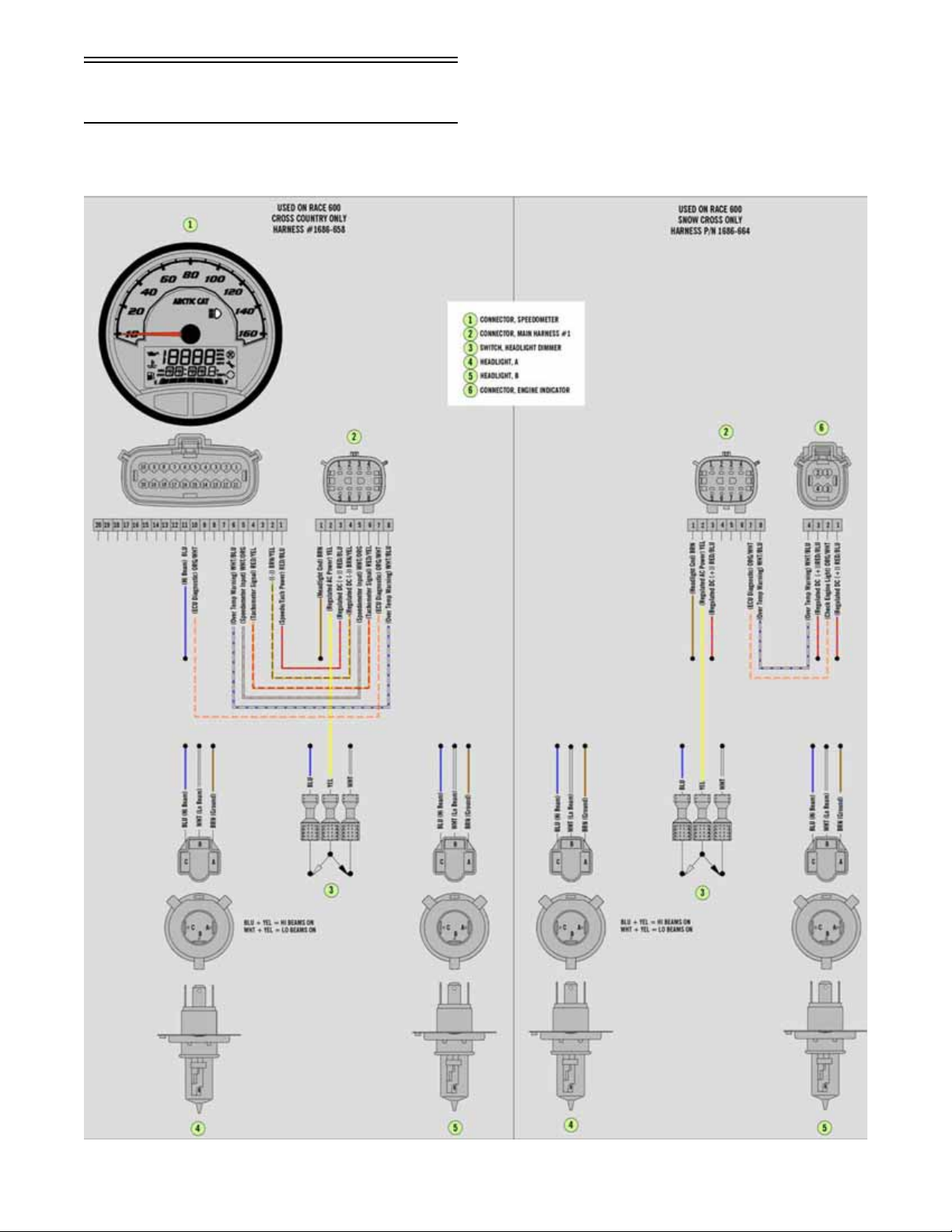
Wiring Diagram - Hood
Harness
(p/n 1686-658) - Cross Country
(p/n 1686-664) - Sno Cross
SNO-2234
19

NOTES
20

Wiring Diagram - Ignition/
Main Harness
(p/n 1686-701)
(Insert 11 x 17 Ill. 0746-250 in color
here.)
21

22
Setup Instructions
This snowmobile has been prepared at the factory to
minimize required setup items; however, there are
some items and inspections that must be done at a
dealership or by the owner/operator. Please pay close
attention to all items on the following pages. Be sure to
read these instructions thoroughly before starting to set
up the snowmobile.
Removing Snowmobile From Crate/
Handlebar Assembly
Installing Spindle/A-Arm
CAUTION
Care should be taken when removing the snowmobile
from the crate. Damage that is not warrantable may
occur.
1. Remove the top and four sides of the crate.
Remove the skis from the crate sides.
2. Remove the windshield and hardware kit.
3. Remove all mounting hardware securing the
snowmobile to the crate base; then lift the snowmobile free of the crate base.
4. Swing the handlebar up and tighten the cap screws
evenly and securely; then check steering for maximum right/left turning capabilities. Install the handlebar pad assembly.
NOTE: Recommended torque value for the cap
screws is 15 ft-lb.
Installing Windshield
746-483A
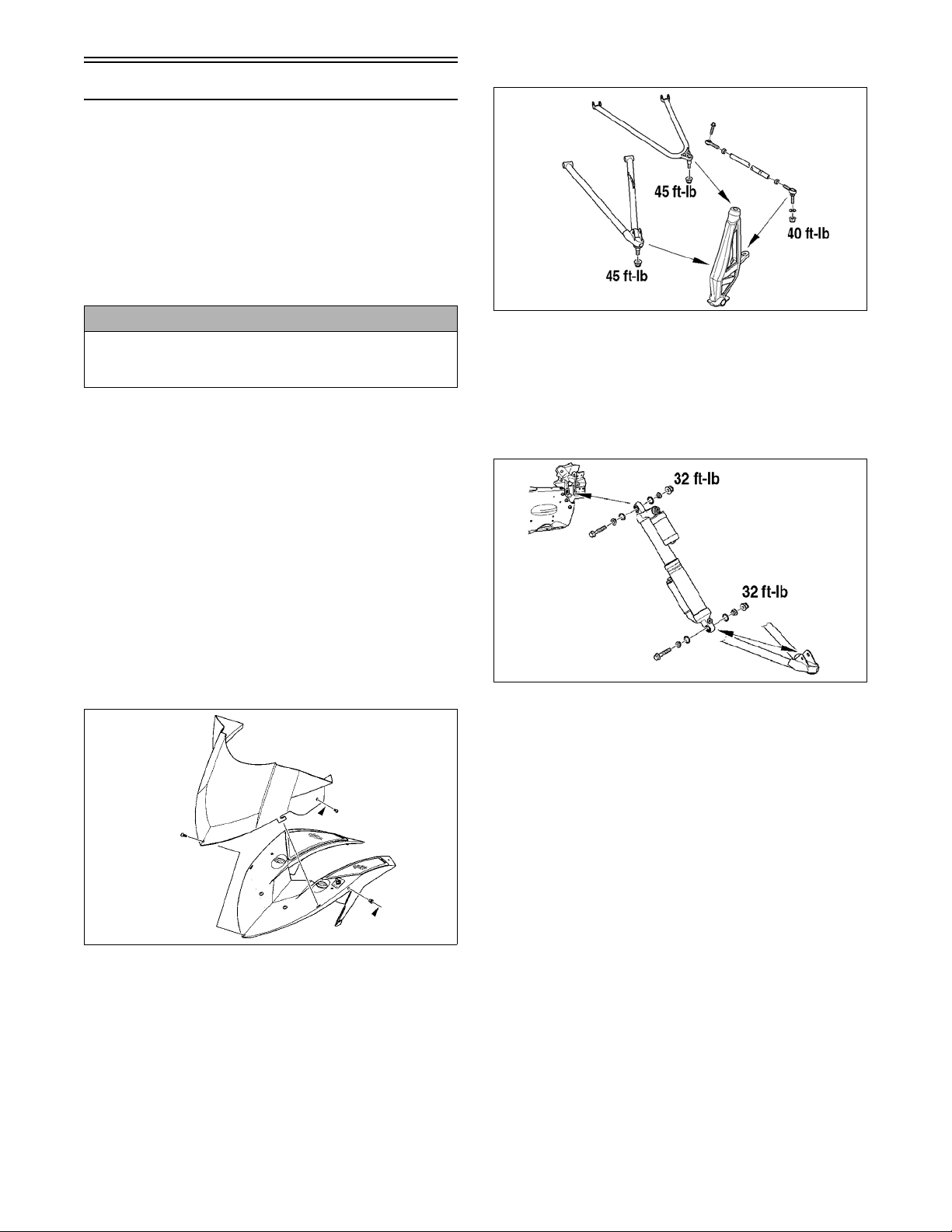
1. Install the A-arms onto the spindle and secure
using new lock nuts. Tighten to 45 ft-lb.
2. Install the steering tie rod to the spindle. Tighten
lock nuts to 40 ft-lb.
Installing Front Shock Absorbers
746-484A
1. Raise the front of the snowmobile and place it on a
support stand.
2. Apply grease to the O-rings; then install the O-rings
and the spherical spacers to each side of the shock
eyelet spherical bearing. Take care that the O-ring is
between the bearing and spherical spacers.
0746-485
1. Install the expansion nuts into the speedometer
bracket; then place the windshield into position on
the console and bracket.
2. Secure the windshield using the four torx-head
screws.
3. Place the upper shock into position on the frame;
then install the cap screw and flange nut. Tighten
to 32 ft-lb.
4. Install the lower shock eyelet into the lower A-arm
mounting bracket.
5. Push the cap screw through the shock eyelet and
backside of the A-arm mounting bracket; then
install the nut and tighten to 32 ft-lb.
6. Install the remaining shock absorber.
Installing Skis
NOTE: The skis are not equipped with wear bars
(see Ski Wear Bar sub- section).
1. Slide a washer onto the cap screw used to secure the
ski; then apply all-temperature grease to the shaft
portion of the cap screw and spindle axle.
23
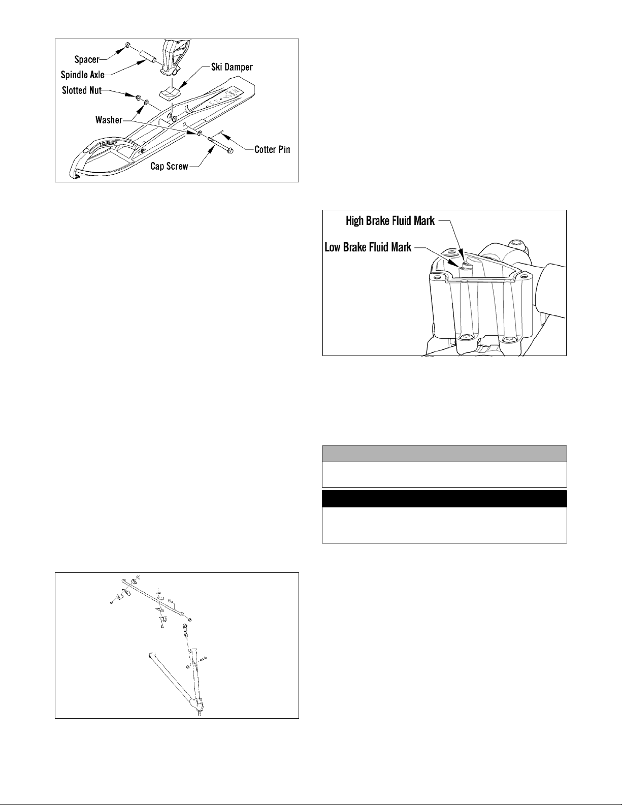
0747-094
Cross Country Ski
2. Install the spindle axle into the spindle; then position the
ski damper into the bottom of the ski making sure the
damper is properly positioned for the desired ski stance.
NOTE: The ski damper must be positioned in the ski
so it is directly under the spindle.
3. With the cap screw hole of the ski centered with the
spindle axle, slide the cap screw with washer through
the outside of the ski and spindle assemblies.
NOTE: Local laws and/or regulations as to maxi-
mum width of the ski stance may be applicable.
Always comply with the maximum width laws and/or
regulations when adjusting ski stance.
NOTE: Install the cap screw so the lock nut will be
located to the inside of the ski and the cotter pin slot
in the cap screw will be horizontal with the ski.
4. Install the remaining washer and lock nut; then
tighten the lock nut to 35 ft-lb.
NOTE: Assure that the cotter pin slot in the cap
screw is still horizontal with the ski (see illustration);
then proceed to step 7.
5. Install the cotter pin from the back side of the ski cap
screw and spread the pin.
NOTE: Repeat this sub-section on the opposite side.
Installing Sway Bar (Optional)
NOTE: Sway Bar Kit (p/n 5639-998/999).
2. Secure the bar with the two mounting brackets,
four machine screws.
3. Tighten machine screws evenly to 8 ft-lb.
4. Position the sway bar link onto the lower A-arm
and the sway bar. Install the cap screws and lock
nuts. Tighten the lock nuts to 23 ft-lb.
Brake System
Checking Brake Fluid
1. With the brake fluid reservoir in a level position,
check the fluid level. The brake fluid level must be
just below the high mark.
SNO-253
2. If the brake fluid level is below the low mark,
remove the reservoir cover and add Arctic Cat
approved brake fluid until the fluid level is just
below the high mark. Install and secure the reservoir cover. Do not allow moisture to contaminate
the brake system.
CAUTION
Brake fluid is highly corrosive. Do not spill brake fluid
on any surface of the snowmobile.
! WARNING
Do not overfill the brake fluid reservoir. Overfilling the
reservoir may cause the brake system to hydraulically
lock. Use only Arctic Cat approved brake fluid.
Checking Brake Lever Operation
1. Test the operation of the hydraulic brake system
by compressing the brake lever.
SNO-2232
1. Place the sway bar into position (mounting location) of the chassis.
24
2. The brake lever must feel firm when compressed.
Drive Belt
Installing Belt
1. Set the brake lever lock; then remove the left-side
access panel.
2. Using Drive Belt Deflection Tool (p/n 0644-424),
thread the tool clockwise into the driven clutch
until the movable sheave opens far enough to
install the drive belt.
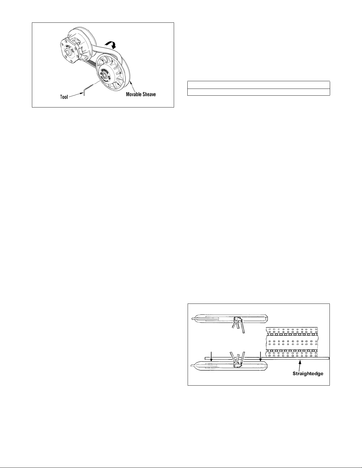
743-067B
3. Place the belt (so the part number can be read)
between the sheaves of the drive clutch.
NOTE: Turning the set screw clockwise increases
distance between the sheaves (increases belt
deflection measurement); turning the set screw
counterclockwise decreases distance between the
sheaves (decreases belt deflection measurement).
Ski Alignment
Checking
Toe-Ou t R a n g e
0.0 - 12.7 mm (0 - 1/2 in.)
NOTE: Track tension and alignment must be properly
adjusted prior to checking or adjusting ski alignment.
Ski alignment must be performed on a flat, level surface. Ski toe-out must fall within the specified range.
4. With the sheaves fully apart, roll the belt over the
stationary sheave.
5. With the drive belt properly positioned in the drive
clutch and driven clutch, turn the belt tool counterclockwise, release the brake lever lock, and roll
the belt back and forth to allow the driven clutch
sheaves to fully close.
6. After the belt is installed properly, install the leftside access panel.
Checking/Adjusting Deflection
Drive belt length, condition, and deflection are all
important for peak performance. To check and adjust
drive belt deflection, use the following procedure.
1. With the engine off; remove the hood and left-side
access panel.
2. Make sure the drive belt is sitting at the top of the
driven clutch sheaves.
3. Place a straightedge on the top of the drive belt.
The straightedge should reach from the drive
clutch to the top of the driven clutch.
4. Using a stiff ruler centered between the drive
clutch and driven clutch, push down on the drive
belt just enough to remove all slack and note the
amount of deflection. The deflection should be
approximately 15.9-22.2 mm (5/8-7/8 in.).
1. Raise the front end of snowmobile just high
enough that the ski shocks are fully extended but
the skis are still resting on the floor.
2. From the riding position on the snowmobile,
check that the handlebar is in a straight-forward
direction for driving.
NOTE: Steering can be centered in the chassis by
taking measurements from each side of the drag
link to a location on the chassis which would be of
equal distance from each side of the drag link.
3. Using a very light hold-down strap (bungee cord)
between the ski handles, apply a very light load
approximately 2-4 lb pulling the skis together just
enough to pull the slack.
NOTE: Track tension and alignment must be
properly adjusted prior to placing the straightedge
against the outside edge of the track.
4. Place a long straightedge against the outside edge
of the track so it lies near the inside edge of the
left-side ski.
NOTE: The amount of deflection should be experimented with or tested to obtain best start-line performance.
NOTE: Push down on the belt with the ruler only
until the bottom of the belt flexes upward; then
read the amount of deflection.
5. To correct drive belt deflection, loosen the jam nut
on the belt width adjuster on the stationary sheave.
6. Using an Allen wrench, adjust the set screw as
needed.
729-887E
NOTE: The straightedge should be long enough to
extend from the back of the track to the front of the ski.
25
5. Measure the distance from the straightedge to the
left-side ski edge in two places: approximately
35.5-38.1 cm (14-15 in.) in front of the spindle and
35.5-38.1 cm (14-15 in.) behind the spindle.
Record the measurements taken for the left side.
729-887D
6. Place the straightedge against the outside edge of the
track so it lies near the inside edge of the right-side ski.
7. Measure the distance from the straightedge to the
right-side ski edge in two places: 35.5-38.1 cm
(14-15 in.) in front of the spindle and 35.5-38.1 cm
(14-15 in.) behind the spindle. Record the measurements taken for the right side.
2. Adjust ski alignment by rotating the tie rod with a
wrench at hex-point (B).
3. When ski alignment is correct, apply blue Loctite
#243 to the jam nut threaded area and tighten to 20
ft-lb. Tighten both jam nuts against the tie rod.
! WARNING
Neglecting to lock the tie rod by tightening the jam
nuts may cause loss of snowmobile control and possible personal injury.
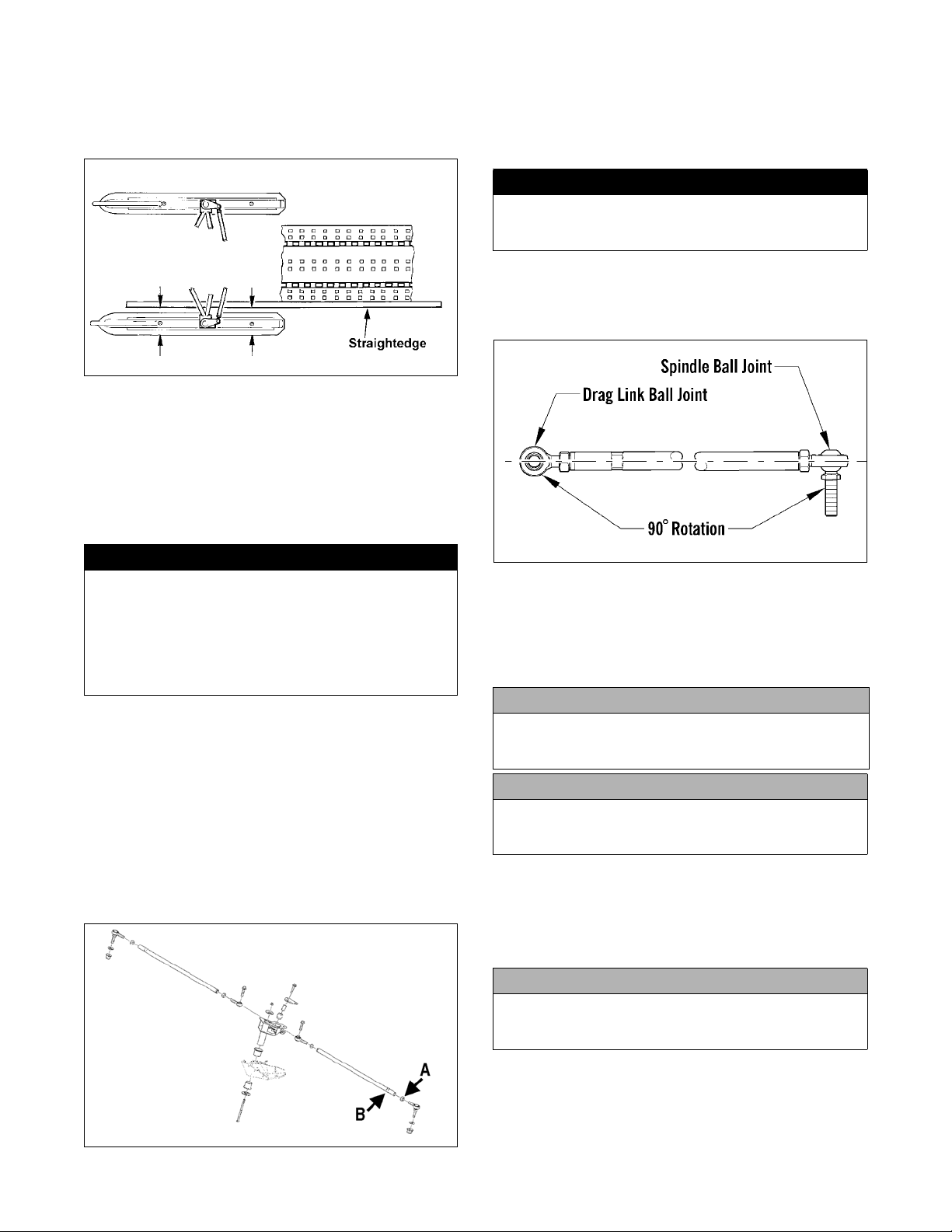
NOTE: To allow equal rotation of the tie rod end
ball joints, secure the tie rod jam nuts with the tie
rod ends positioned 90° from each other.
! WARNING
The measurement from the front and rear of ski to the
straightedge can be equal (ski parallel to the track),
but the front measurement must never be less (ski
toed-in) or poor handling will be experienced. The
front measurements to the straightedge must not
exceed the rear measurements to the straightedge (ski
toed-out) by more than 12.7 mm (1/2 in.).
8. If ski alignment is not as specified, adjust the alignment of the ski(s) not parallel to the straightedge.
Adjusting
NOTE: The following procedure can be used to
adjust the alignment of either ski.
1. Unlock the steering tie rod by loosening jam nuts (A).
NOTE: The inside jam nuts are left-hand thread. Care
should be taken to rotate them in the proper direction.
0743-088
Recommended Gasoline/Oil/Mixing
Ratio
The recommended gasoline to use is non-oxygenated
91 minimum octane.
CAUTION
When operating this snowmobile on the 91 minimum
octane non-oxygenated gasoline, the ignition timing dial
must be set to -3° or severe engine damage may occur.
CAUTION
Do not use white gas or gasoline containing methanol.
Only Arctic Cat approved gasoline additives should be
used.
The recommended oil to use as a pre-mix for engines
with variable exhaust valves is Arctic Cat Synthetic
APV 2-Cycle Oil. This oil is specially formulated to be
used as a pre-mix oil and meets all of the lubrication
requirements of the Arctic Cat Snowmobile engine.
CAUTION
Any oil used in place of the recommended oil could
cause serious engine damage and could lead to carbon buildup on the exhaust valves.
26
SNO-2233A
 Loading...