How it Works
Log In / Sign Up
Buy Points
How it Works
FAQ
Contact Us
Questions and Suggestions
Users
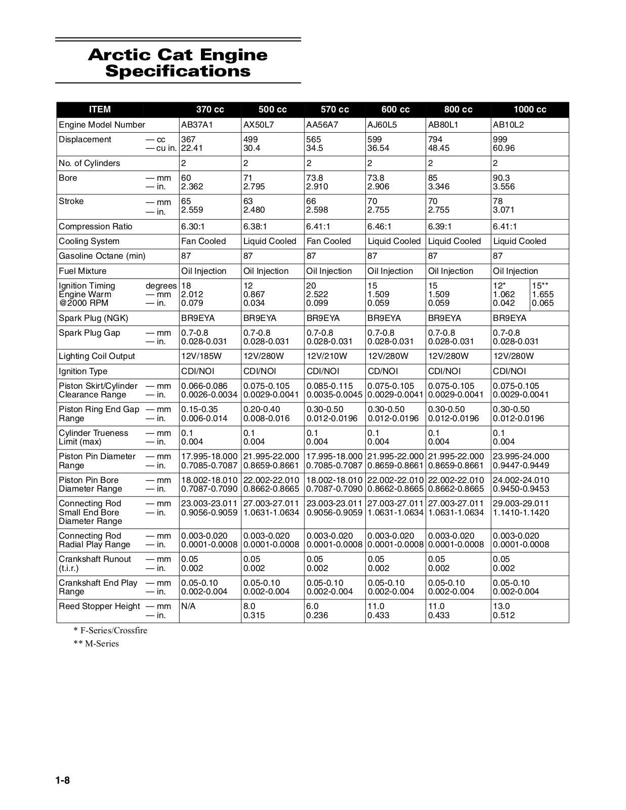
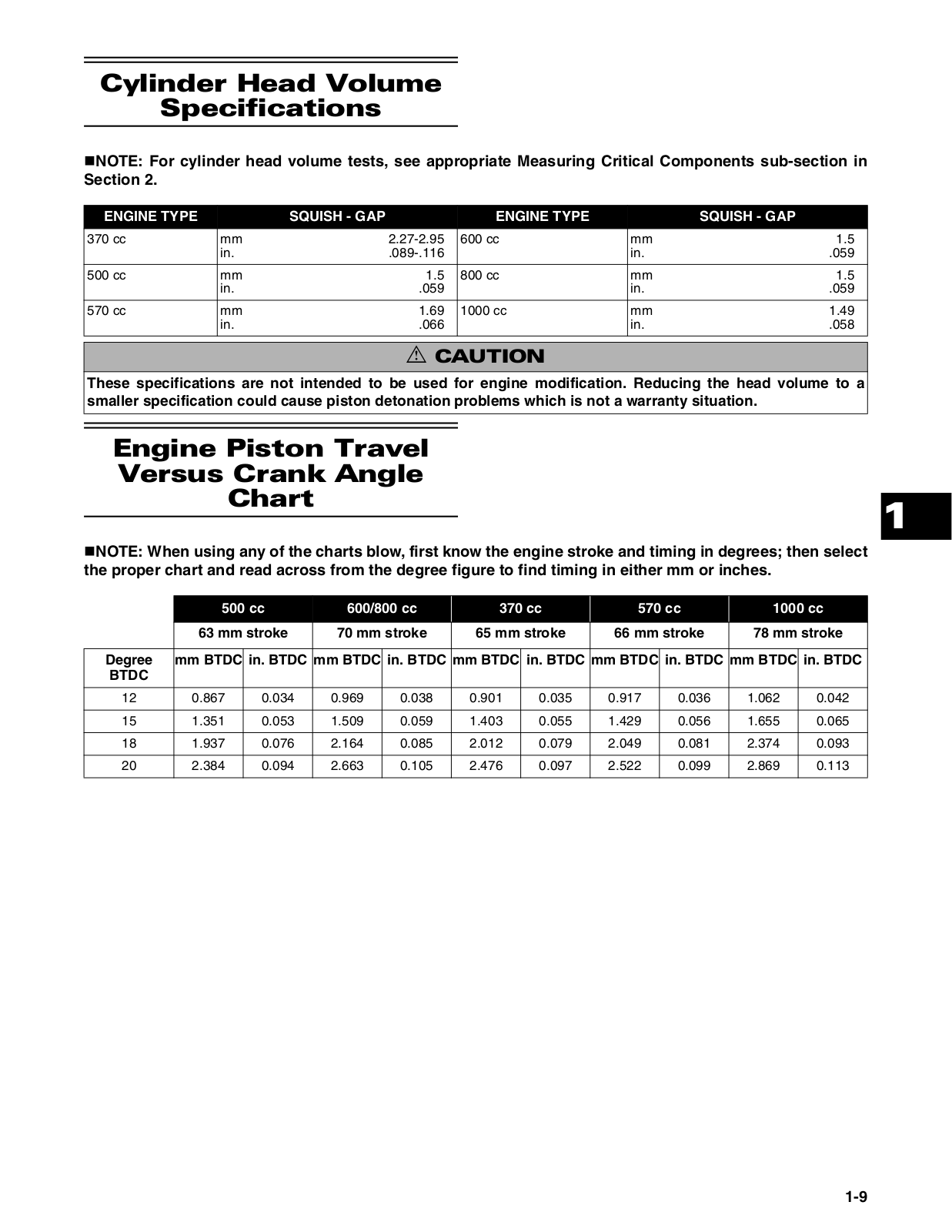
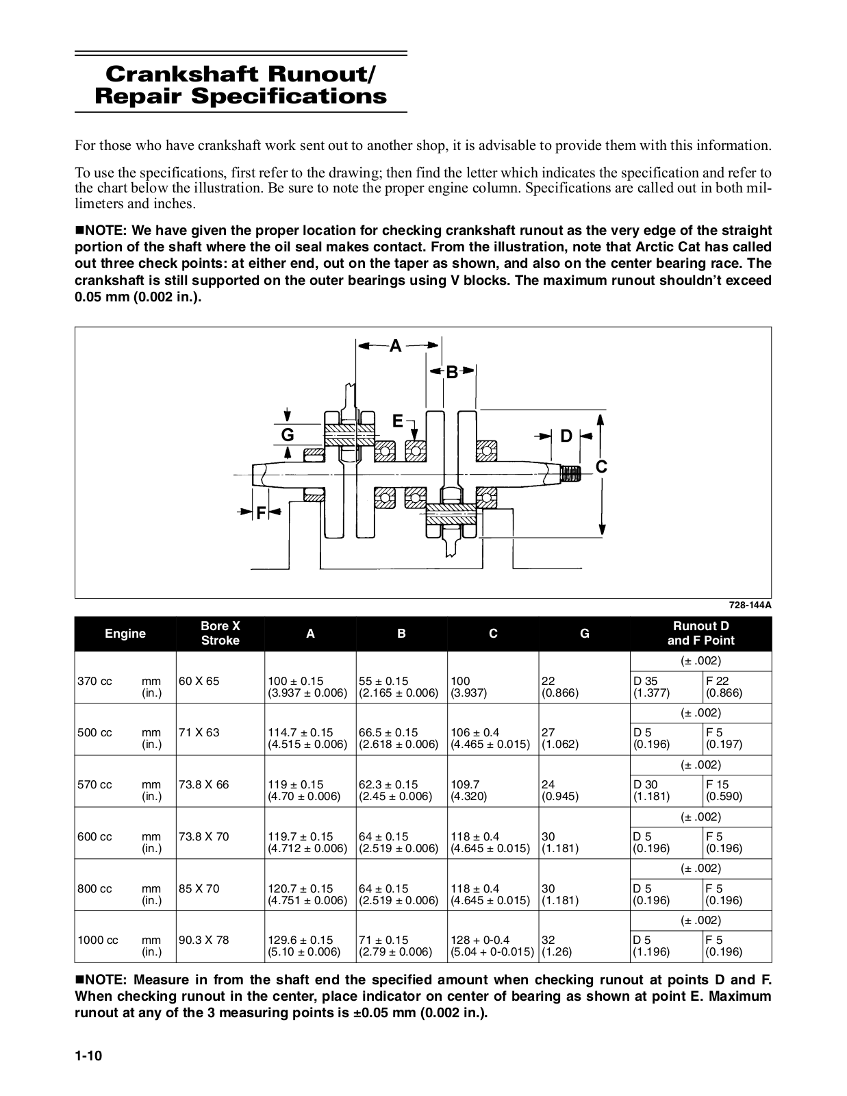
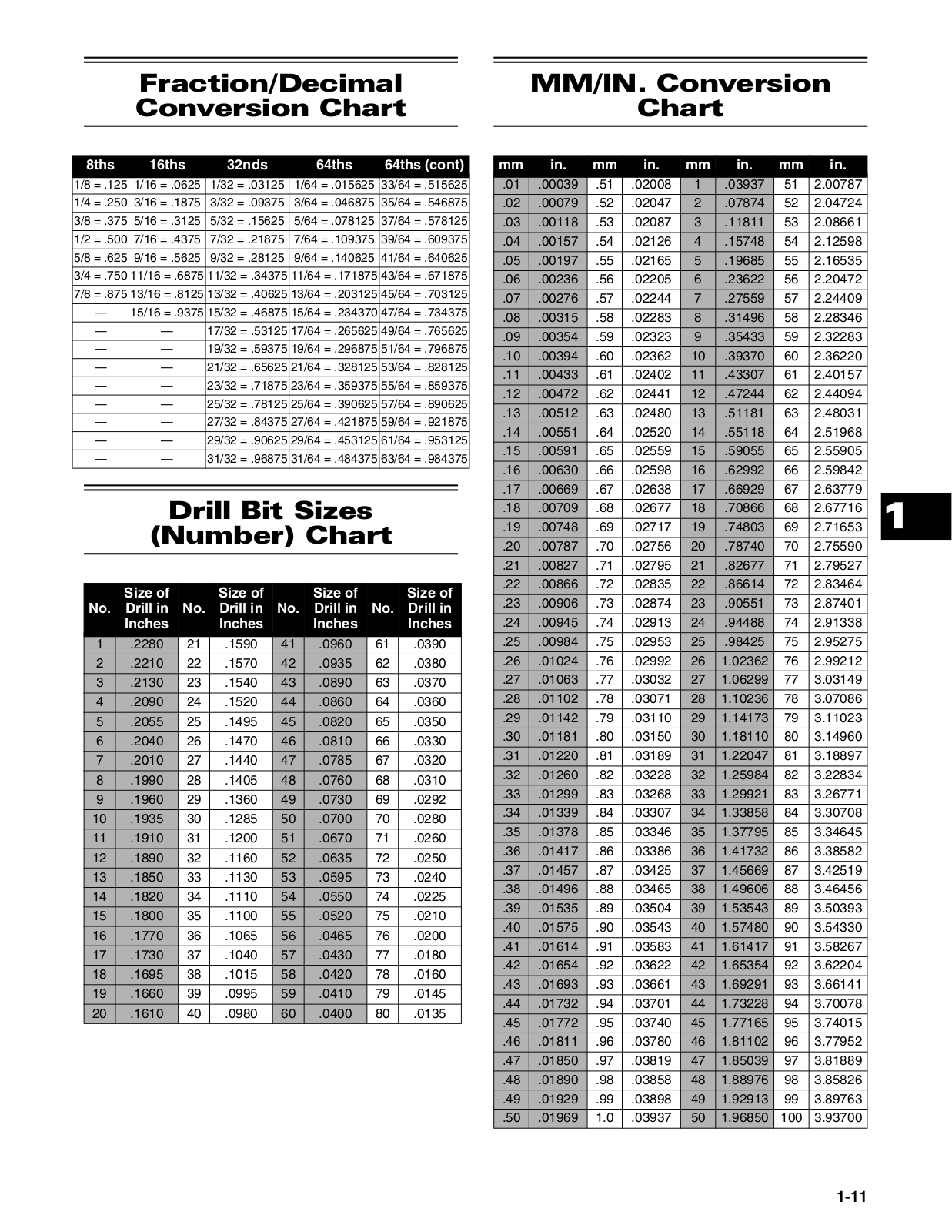
Arctic Cat
Loading...
#
700i
700 i TBX (2012)
700 i TRV/GT (2012)
700 TRV LIMITED
700 TRV XT
90 Utility (2012)
8000 2021
9000 2021
9000 2022
9000 2023
A
A2006TBM4BUSR
ALTERRA 550i
ALTERRA 700i
ALTERRA 700 XT
ALTERRA TRV 1000i
ALTERRA TRV 1000 XT
ALTERRA TRV 550i
ALTERRA TRV 550 XT
ALTERRA TRV 700i
ALTERRA TRV 700 XT
C
Cheetah
Cheetah 1977
Cheetah 1978
2
Cougar
D
DVX 300
3
DVX 300 (2012)
E
EI Tigre 5000 1980
EI Tigre 5000 1981
El Tigré
J
Jag 1978
Jag 1987
L
L7825
M
M 7000 (2015)
M 9000 (2015)
P
P8814
Pantera
Pantera 1978
Pantera 7000 (2015)
Panther 1977
Panther 1978
2
Panther 1979
Panther 1987
S
S2005BCFWTOSS
S2005BCFWTUSS
SD-ROM 2002
SD-ROM 2003
SD-ROM 2004
SD-ROM 2005
SD-ROM 2006
SD-ROM 2007
SD-ROM 2008
2
SD-ROM 2009
SD-ROM 2010
SD-ROM 2011
SD-ROM 2012
Sno Pro 600 2013
Snowmobile
SNOWMOBILE 2015
SNOWMOBILE 2016
Snowmobiles 2014
Super Jag 1987
W
WILD 2014
X
XC 450
2
XC 450 i (2012)
XF 7000 (2015)
XF 7000 High Country (2015)
XF 9000 (2015)
XF 9000 High Country (2015)
XR 550i XT
XR 700i
XR 700i XT
Z
ZR 6000R CC 2015
ZR 6000 R Cross Country 2016
ZR 6000 R Sno Cross 2016
ZR 6000R SX
ZR 6000R XC
ZR 6000R XC 2018
ZR 7000 (2015)
ZR 9000 (2015)
ZR /Riot /M/Norseman X 6000
ZR /Riot /M/Norseman X 8000
ZR/XF/M 2-STROKE
ZR/XF/M 4000
ZR/XF/M 4000 2016
ZR/XF/M 4000 2017
ZR/XF/M 6000
ZR/XF/M 6000 2016
ZR/XF/M 6000 2017
ZR/XF/M 8000
ZR/XF/M 8000 2016
ZR/XF/M 8000 2017
ZR-XF-M 9000 2017
ZR/XF/M Pantera 5000
ZR/XF/M Pantera 7000
ZR/XF/M Pantera 9000
ZR/XF/M Pantera/Notseman 3000
ZR/XF/M Pantera/Notseman 6000
ZR/XF/M Pantera/Notseman 7000
ZR/XF/M Pantera/Notseman 8000
ZR/XF/M Pantera/Notseman 9000
Loading...
Loading...
Nothing found
SD-ROM 2008
Service Manual
473 pgs
153.15 Mb
0
Service Manual
654 pgs
174.82 Mb
0
Table of contents
Loading...
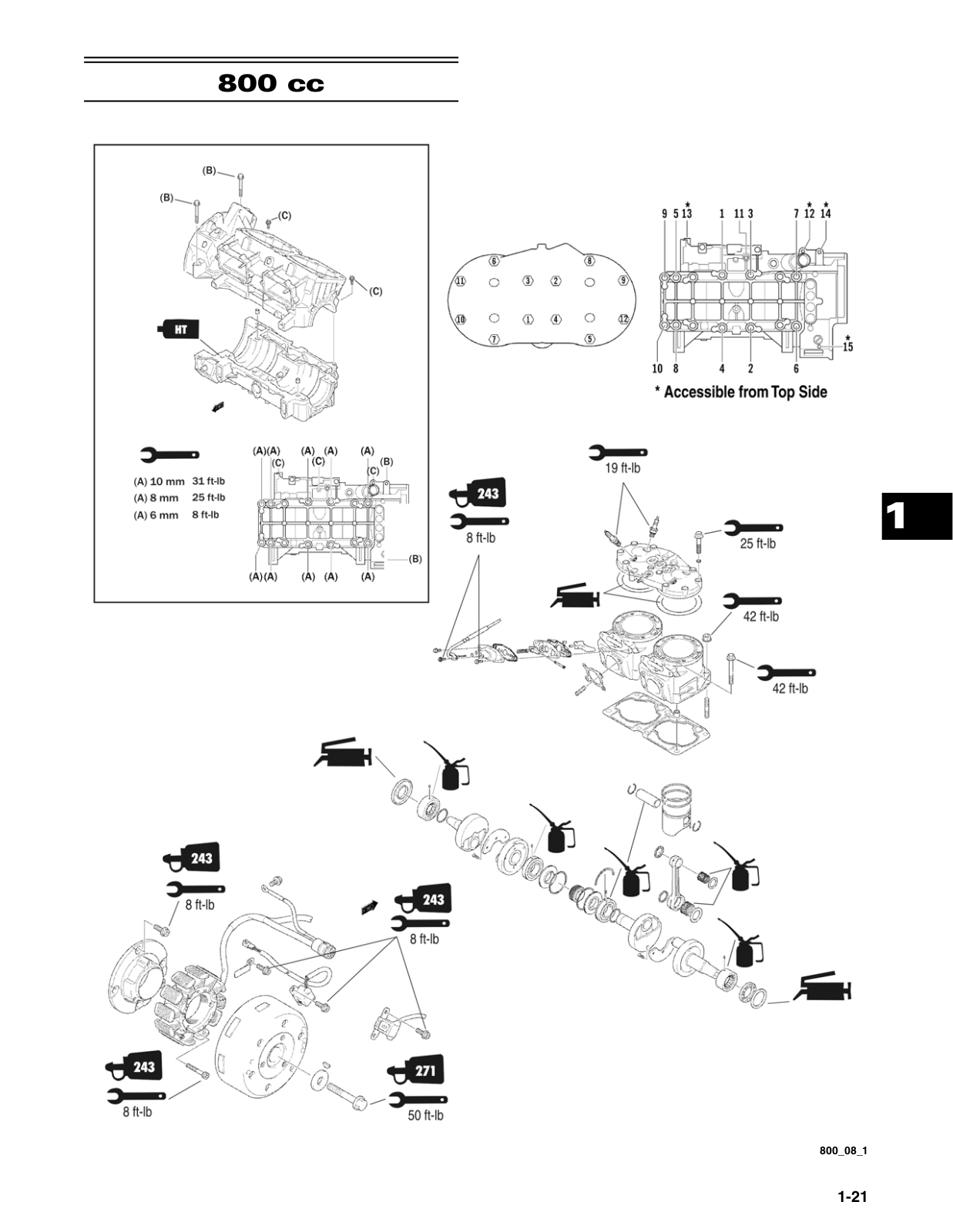
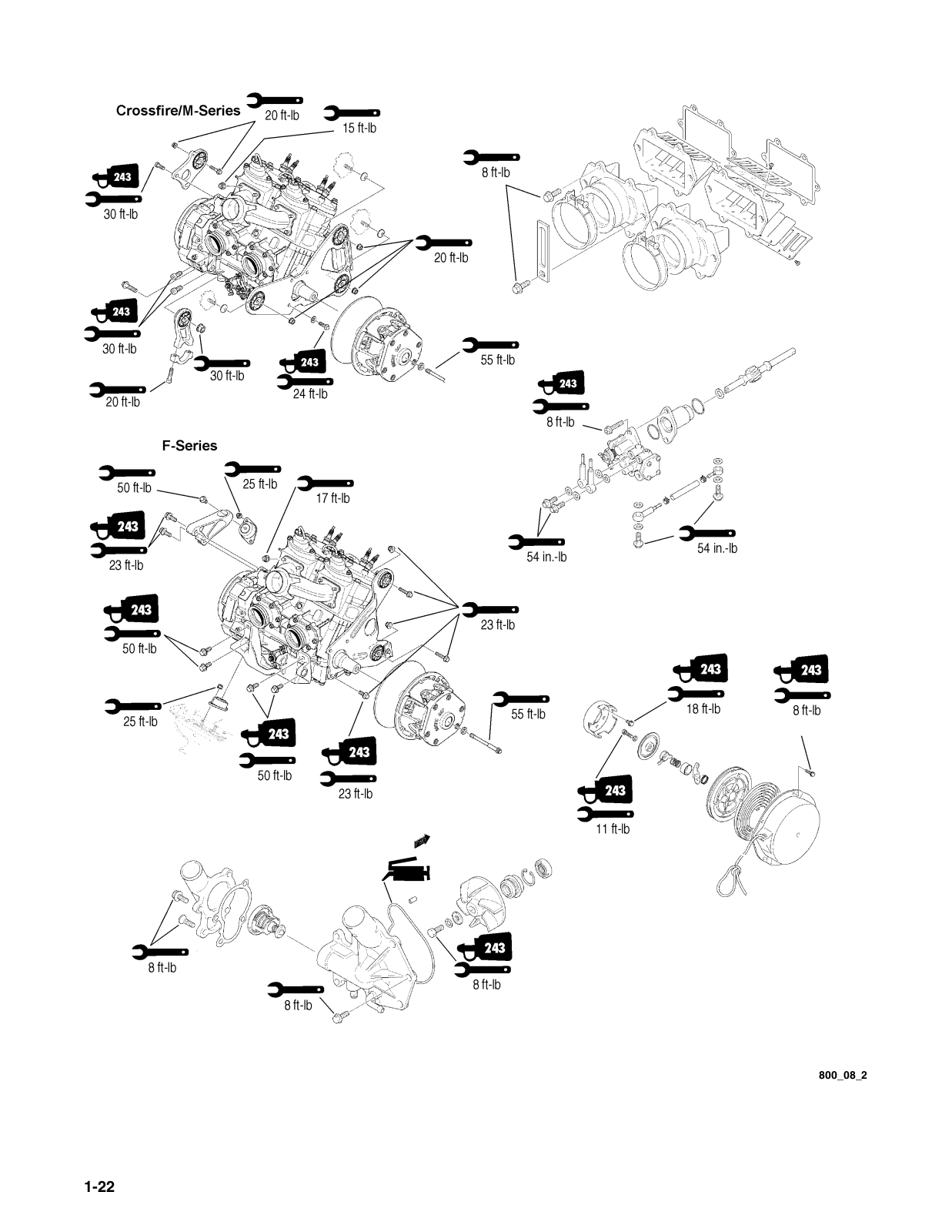
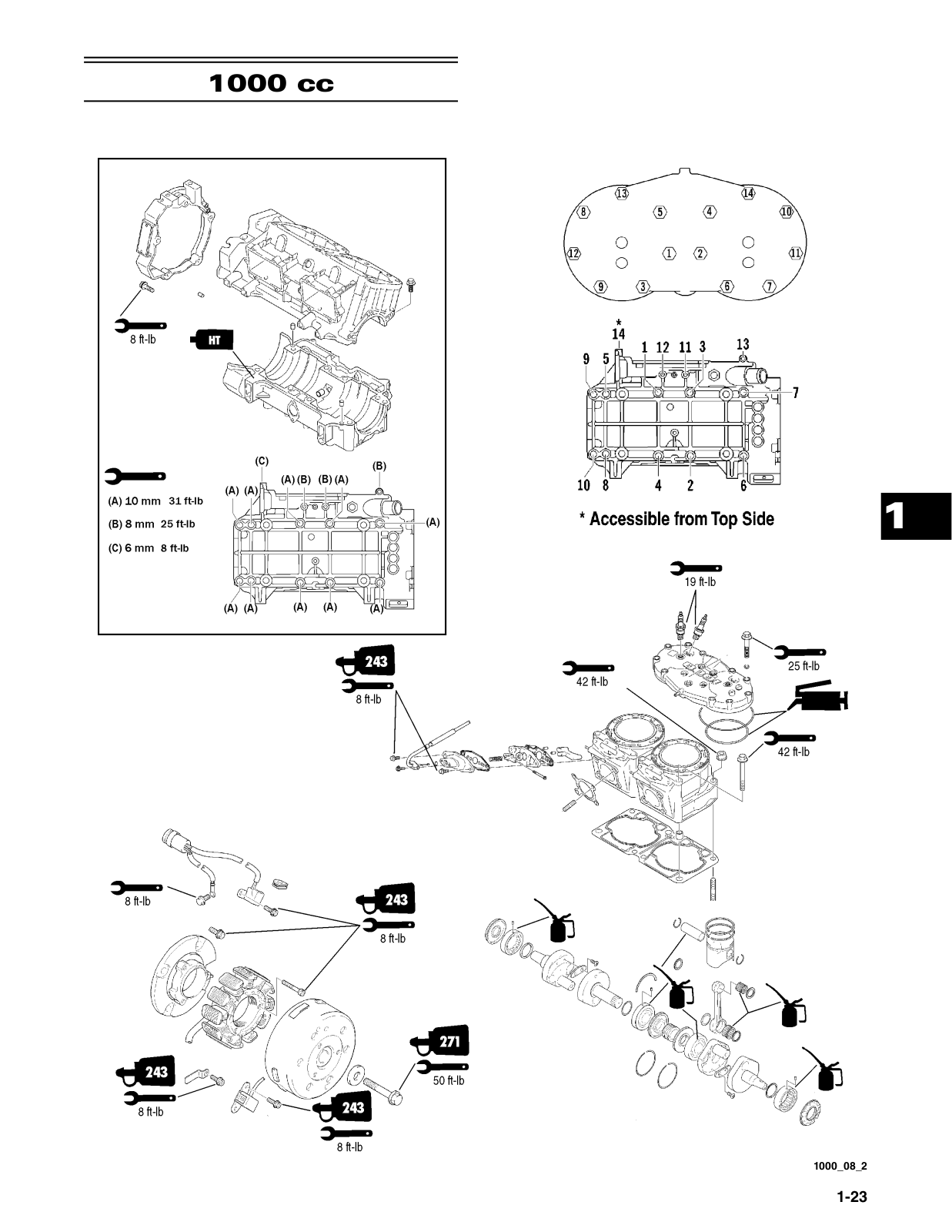
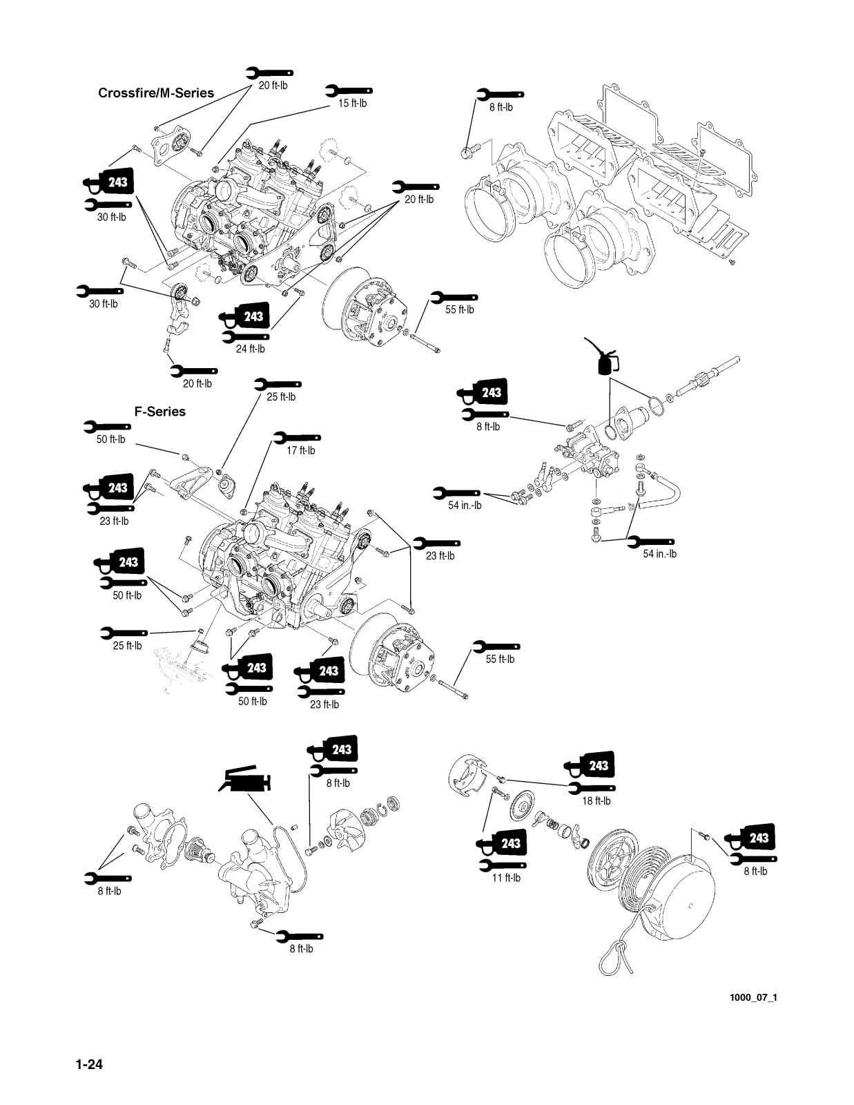
Arctic Cat SD-ROM 2008 Service Manual
...
Arctic Cat Service Manual
Download
Specifications and Main Features
Frequently Asked Questions
User Manual
Download
Loading...
+
624
hidden pages
Unhide
You need points to download manuals.
1 point = 1 manual.
You can buy points or you can get point for every manual you upload.
Buy points
Upload your manuals