

Arctic Cat SD-ROM 2006 Service Manual

FOREWORD
This Arctic Cat Service Manual contains service and maintenance information for the Model Year 2006 Arctic Cat
Snowmobiles. This manual is designed to aid service personnel in service-oriented applications.
This manual is divided into sections. The sections cover specific snowmobile components or systems and, in addition
to the standard service procedures, includes assembling, disassembling, and inspecting instructions. When using this
manual as a guide, the technician should use discretion as to how much disassembly is needed to correct any given condition.
The service technician should become familiar with the operation and construction of the components or systems by
carefully studying the complete manual. This will assist the service technician in becoming more aware of and efficient
with servicing procedures. Such efficiency not only helps build consumer confidence but also saves time and labor.
All Arctic Cat publications and snowmobile decals display the words Warning, Caution, and Note to emphasize important information. The symbol ! WARNING identifies personal safety-related information. Be sure to follow the
directive because it deals with the possibility of severe personal injury or even death. The symbol ! CAUTION
identifies unsafe practices which may result in snowmobile-related damage. Follow the directive because it deals with
the possibility of damaging part or parts of the snowmobile. The symbol NOTE: identifies supplementary informa-
tion worthy of particular attention.
At the time of publication, all information, photographs, and illustrations were technically correct. Some photographs
and illustrations used in this manual are used for clarity purposes only and are not designed to depict actual conditions.
Because Arctic Cat Inc. constantly refines and improves its products, no retroactive obligation is incurred.
All materials and specifications are subject to change without notice.
Keep this manual accessible in the shop area for reference.
Product Service and Warranty Department
Arctic Cat Inc.
© 2005 Arctic Cat Inc. October 2005
®™ Trademarks of Arctic Cat Inc., Thief River Falls, MN
Back to TOC

TABLE OF
CONTENTS
Foreword
Section
1. General Information
2. Engine
3. Engine-Related Items
Click on the Red Text to go.
4. Fuel Systems
5. Engine Electrical Systems
6. Chassis Electrical Systems
7. Steering and Body
8. Drive Train and Brake Systems
9. Track/Rear Suspension

SECTION 1 — GENERAL INFORMATION
1
Snowmobile Identification ....................................... 1-2
Recommended Gasoline and Oil ........................... 1-2
Break-In Procedure ................................................ 1-2
Genuine Parts ........................................................ 1-3
High Altitude Operation .......................................... 1-3
Preparation For Storage ......................................... 1-3
Preparation After Storage ...................................... 1-5
After Break-In Checkup (100 Miles) ....................... 1-5
After Break-In Checkup Checklist .......................... 1-6
Torque Conversions ............................................... 1-7
Tightening Torque (General Bolts) ........................ 1-7
Fraction/Decimal Conversion Chart ....................... 1-8
Drill Bit Sizes (Number) Chart ................................ 1-8
MM/In. Conversion Chart ....................................... 1-9
Servicing Symbols ............................................... 1-10
Back to TOC
TABLE OF
CONTENTS
1-1
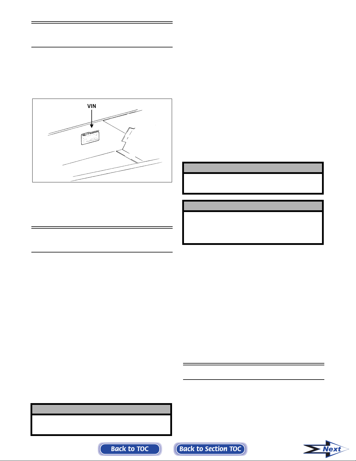
Snowmobile
Identification
The Arctic Cat Snowmobile has two important identification numbers. The Vehicle Identification Number (VIN) is stamped into the tunnel near the rightside footrest. The Engine Serial Number (ESN) is
stamped into the crankcase of the engine.
0726-383
These numbers are required to complete warranty
claims properly. No warranty will be allowed by
Arctic Cat Inc. if the engine serial number or VIN is
removed or mutilated in any way.
Recommended
Gasoline and Oil
RECOMMENDED GASOLINE
(Carbureted Models)
RECOMMENDED GASOLINE
(EFI Models)
The recommended gasoline to use in these snowmobiles is 87 minimum octane regular unleaded. In
many areas, oxygenates (either ethanol or MTBE)
are added to the gasoline. Oxygenated gasolines containing up to 10% ethanol or up to 15% MTBE are
acceptable gasolines. Do not use gasolines containing methanol.
NOTE: On the 700 cc and 900 cc engines when
using the recommended gasoline, the Fuel Designation Connector (the gray wire at the ECU) must
be connected.
NOTE: On the 700 cc and 900 cc engines when
using oxygenated gasolines, the Fuel Designation
Connector (the gray wire at the ECU) must be disconnected.
! CAUTION
Do not use white gas or gasoline containing methanol. Only Arctic Cat approved gasoline additives
should be used.
! CAUTION
On the 700 cc and 900 cc engines if oxygenated
gasoline is to be used, it is extremely important that
the Fuel Designation Connector at the ECU is disconnected. If not, severe engine damage may
occur.
NOTE: On the 700 cc and 900 cc engines in order
for the ECU to change modes, the engine must be
OFF when connecting or disconnecting the Fuel
Designation Connector.
The recommended gasoline to use in these snowmobiles is 87 minimum octane regular unleaded. In
many areas, oxygenates (either ethanol or MTBE)
are added to the gasoline. Oxygenated gasolines containing up to 10% ethanol or up to 15% MTBE are
acceptable gasolines; however, whenever using oxygenated gasolines, the carburetor main jet must be
one size larger than the main jet required for regular
unleaded gasoline. For example, if a 400 main jet is
recommended for regular unleaded gasoline, a 410
main jet must be installed if using an oxygenated
gasoline.
When using ethanol blended gasoline, it is not necessary to add a gasoline antifreeze since ethanol will
prevent the accumulation of moisture in the fuel system.
! CAUTION
Do not use white gas or gasolines containing methanol. Only Arctic Cat approved gasoline additives
should be used.
1-2
Back to TOC
RECOMMENDED OIL
The recommended oil to use in the oil-injection system is Arctic Cat 50:1 Injection Oil (for standard
models) or Arctic Cat Synthetic APV 2-Cycle Oil
(for APV models). The oil is specially formulated to
be used either as an injection oil or as a pre-mix oil
(for carbureted model break-in) and meets all of the
lubrication requirements of the Arctic Cat snowmobile engine.
Break-In Procedure
The Arctic Cat 2-stroke engine (when new or rebuilt)
requires a short break-in period before the engine is
subjected to heavy load conditions. Arctic Cat
requires that the first tankful of fuel be premixed at a
100:1 ratio in all oil-injection models.
Back to Section TOC
Next
During the break-in period, a maximum of 1/2 throttle is recommended; however, brief full-throttle
accelerations and variations in driving speeds contribute to good engine break-in.
! CAUTION
DO NOT exceed the one (1) tankful limitation of a
100:1 gas/oil break-in mixture. Continuous use of a
gas/oil mixture, unless consistently operating in
extremely cold conditions (-26°C/-15°F or colder),
could cause spark plug fouling and excessive carbon buildup. A 100:1 gas/oil mixture must be used
in conjunction with the oil-injection system to
ensure adequate engine lubrication in extremely
cold conditions.
Genuine Parts
When replacement of parts is necessary, use only
genuine Arctic Cat parts. They are precision-made to
ensure high quality and correct fit.
High Altitude Operation
1. Clean the seat cushion with a damp cloth and
Arctic Cat Vinyl Protectant (p/n 0638-313).
2. Clean the snowmobile thoroughly by hosing dirt,
oil, grass, and other foreign matter from the skid
frame, tunnel, hood, and belly pan. Allow the
snowmobile to dry thoroughly. DO NOT get
water into any part of the engine.
3. Place the rear of the snowmobile up on a
shielded safety stand.
NOTE: On 500/600/700 cc models, the air silencer
boot can be pried forward to access the intake
bores. Pry the boot forward; then proceed to step
7.
NOTE: On some standard models, the air-intake
silencer is a one-piece unit, and the silencer
boot(s) can be removed to access the intake
bore(s). Remove the boots; then proceed to step 7.
NOTE: On some standard models, the air-intake
silencer includes a cover/tool tray assembly and a
baffle/resonator, and the silencer boot cannot be
removed to access the intake bores. Proceed to
step 4.
1
Operating a snowmobile at varying altitudes requires
changes in performance components. These changes
affect drive train components (on all models) and
carburetion components (on carbureted models).
High altitude information decal(s) are located
beneath the hood of the snowmobile.
! CAUTION
On carbureted models, carefully follow the Main Jet
Chart recommendations for proper main jet selection for altitude, temperature, and gasoline being
used.
King Cat and M-Series snowmobiles are initially set
up at the factory for operation between 6000-9000
feet. Consult the appropriate specifications for this
information.
Preparation For Storage
Prior to storing the snowmobile, it must be properly
serviced to prevent corrosion and component deterioration. An authorized Arctic Cat Snowmobile
dealer should perform this service; however, the
owner/operator can perform this service if desired.
To prepare the snowmobile for storage, Arctic Cat
recommends the following procedure:
4. Open the air-intake silencer cover; then remove
the three screws securing the cover/tool tray
assembly to the silencer.
5. Close the cover; then tip the cover/tool tray
assembly forward and out of its slots and remove
the assembly.
6. Using a large flat-blade screwdriver, remove the
baffle/resonator tabs from the air-intake silencer
slots and remove the baffle/resonator to access
the intake bores.
NOTE: The baffle/resonator can be removed
more easily by removing the back tabs first.
7. Start the engine and allow to idle. With the
engine idling, spray Arctic Cat Engine Storage
Preserver (p/n 0636-177) into the intake(s) until
the engine exhaust starts to smoke heavily or
until the engine starts to drop in RPM. Turn
engine off.
NOTE: On 500/600/700 cc models, secure the air
silencer boots onto the intake bores.
NOTE: On some standard models, install the airintake silencer boot(s); on some standard models,
install the baffle/resonator and the cover/tool tray
assembly.
8. Plug the exhaust system outlet with a clean cloth.
Back
Back to TOC
9. With the ignition switch in the OFF position:
Back to Section TOC
1-3
Next
A. Disconnect the high tension lead(s) from the
spark plug(s); then remove the plug(s), connect it/them to the lead(s), and ground it/them
on the cylinder head(s).
! CAUTION
Never crank the engine over without grounding the
spark plug(s). Damage to coils and/or CDI unit may
result.
B. Pour 29.5 ml (1 fl oz) of SAE #30 petroleum-
based oil into each spark plug hole and pull
the recoil starter handle slowly about 10
times.
C. Install the spark plug(s) and connect the high
tension lead(s).
10. On carbureted models, drain the gas from each
carburetor float chamber.
11. Fill the gas tank to its rated capacity; then add
Arctic Cat Fuel Stabilizer (p/n 0638-165) to the
gas tank following directions on the container
for the stabilizer/gasoline ratio. Tighten the gas
tank cap securely.
12. On models with a chain case, drain the lubricant
by removing the chain-case drain plug located
on the backside of the chain-case assembly.
Remove the chain-case cover and inspect chain,
sprockets, chain tensioner, and rollers for wear
and the chain for proper tension. Install the drain
plug, chain-case cover, and seal; then pour Arctic Cat Transmission Lube (p/n 0636-817) into
the filler hole - 236 ml (8 fl oz) for standard
transmission or 354 ml (12 fl oz) for reverse
transmission.
13. On models with a gear case, drain the fluid from
the gear case. Install the drain plug; then pour
Arctic Cat Synthetic ACT Drive Fluid (p/n
4639-025) into the gear case - 89 ml (3 fl oz).
14. Clean and inspect the drive clutch and driven
pulley.
18. Tighten all nuts, bolts, and cap screws making
sure all calibrated nuts, bolts, and cap screws are
tightened to specifications. Make sure all rivets
holding the components together are tight.
Replace all loose rivets.
19. Clean and polish the hood, console, and chassis
with Arctic Cat Hood and Windshield Cleaner/
Polish (p/n 0636-174). DO NOT USE SOLVENTS OR SPRAY CLEANERS. THE PROPELLENT WILL DAMAGE THE FINISH.
20. On electric start models, disconnect the battery
cables making sure to disconnect the negative
cable first; then clean the battery posts and
cables.
! CAUTION
On models with remote start, make sure to leave
the battery cables disconnected. Failure to disconnect the battery cables when storing the
snowmobile for a prolonged period of time (six
weeks or more) will result in a discharged or
damaged battery.
21. If possible, store the snowmobile indoors. Raise
the track off the floor by blocking up the back
end making sure the snowmobile is secure.
Loosen the track adjusting bolts to reduce track
tension. Cover the snowmobile with a machine
cover or a heavy tarpaulin to protect it from dirt
and dust.
22. If the snowmobile must be stored outdoors, position the snowmobile out of direct sunlight; then
block the entire snowmobile off the ground making sure the snowmobile is secure. Loosen the
track adjusting bolts to reduce track tension.
Cover with a machine cover or a heavy tarpaulin
to protect it from dirt, dust, and rain.
! CAUTION
Avoid storing in direct sunlight and using a plastic
cover as moisture may collect on the snowmobile
causing corrosion.
Back
15. Remove the drive belt from the drive clutch/
driven pulley. Lay the belt on a flat surface or
slide it into a cardboard sleeve to prevent warping or distortion during storage; then clean and
inspect the drive clutch and driven pulley.
16. Apply light oil to the upper steering post bushing, ski spindles and bolts, front and rear pivot
bushings of the skid frame, and plungers of the
shock absorbers.
17. Lubricate all grease fittings (front and rear suspension, spindles, speedometer drive adapter,
and the driven shaft support bearing) with a lowtemperature grease.
1-4
Back to TOC
Back to Section TOC
Next
Preparation After
Storage
Taking the snowmobile out of storage and correctly
preparing it for another season will assure many
miles and hours of trouble-free snowmobiling. Arctic Cat recommends the following procedure:
10. Adjust the carburetor(s) and choke cable on carbureted models and throttle cable on all models.
! WARNING
On VM-style carburetors, be sure to tighten the swivel
adapter jam nuts securely. If a jam nut isn’t tightened,
the adjuster can rotate out of the carburetor cap causing the piston valve not to return to the full-closed
position.
! CAUTION
On carbureted models if the gas in each carburetor
float chamber was not drained prior to storage, the
carburetor(s) must be cleaned before starting the
engine.
1. Clean the snowmobile thoroughly. Polish the
exterior of the snowmobile.
2. Clean the engine. Remove the cloth from the
exhaust system. Check exhaust system and airintake silencer/air filter for obstructions.
3. Inspect all control wires and cables for signs of
wear or fraying. Replace if necessary. Use cable
ties or tape to route wires and cables away from
hot or rotating parts.
4. Inspect the drive belt for cracks and tears. Check
belt specifications. Replace if damaged or worn.
Install the drive belt.
NOTE: If the old belt is worn but in reasonable
condition, retain it with the snowmobile as a spare
in case of emergency.
11. Tighten all nuts, bolts, and cap screws making
sure all calibrated nuts, bolts, and cap screws are
tightened to specifications.
12. Lubricate all grease fittings (rear suspension,
spindles, speedometer drive adapter, and the
driven shaft support bearing) with a low-temperature grease.
13. On liquid cooled models, check the coolant level
and all coolant hoses and connections for deterioration or cracks. Add properly mixed coolant as
necessary.
14. On fan cooled models, clean the engine cooling
fins and all vents.
15. On electric start models, charge the battery; then
connect the battery cables making sure to connect the positive cable first. Test the electric start
system.
After Break-In Checkup
(100 Miles)
1
5. On carbureted models, inspect the in-line fuel
filter and replace if necessary.
6. Inspect all fuel hoses and oil hoses for deterioration or cracks; replace if necessary . Make sure all
connections are tight; then fill the oil-injection
reservoir with the recommended injection oil.
NOTE: After prolonged storage, Arctic Cat recommends one tankful of 100:1 gas/oil mixture be
used in conjunction with the oil-injection system to
ensure proper lubrication.
7. Inspect the entire brake system, all controls,
headlight, taillight, brakelight, ski wear bars, and
headlight aim; adjust or replace as necessary.
8. Inspect each spark plug. Replace, gap, or clean
as necessary.
9. Adjust the track to the proper tension and alignment. Lock the jam nuts.
The 100 mile checkup offered by some dealerships
reduces problems and warranty costs. A program of
this kind should be offered by all dealerships. Many
dealerships have added the price of the checkup into
the selling price of the snowmobile, and others offer
it as a bonus to the customers who purchase snowmobiles from their dealership.
There are three areas that require adjustment after
the break-in period in order to obtain peak performance. These areas are the following.
A. Carburetor jetting
B. Drive belt deflection/Break-In
C. Track tension and alignment
CARBURETOR JETTING (Carbureted Mod-
Altitude, temperature, and the use of oxygen-
els)—
ated gasoline affect the carburetion needed for
optimum engine performance. The carburetor main
jets must be changed in conjunction with changes in
operating altitude, oxygenated gasoline usage, and
temperature.
Back
Back to TOC
Back to Section TOC
1-5
Next

DRIVE BELT DEFLECTION — Drive belt
deflection is very important to the snowmobile. Even
if it is checked and is correct when the snowmobile
is set up, it does change (more so during the break-in
period). This is because the rubber engine mounts
and the rubber snubber on the torque link will all
take a “set” during the first 100 miles, which allows
the distance between the drive clutch and driven pulley to shorten. When this happens, the snowmobile
will appear to have a too long drive belt. To add to
this, the drive belt itself wears and stretches somewhat. This all leads to a low-end performance problem and, if not corrected, causes premature drive belt
wear.
After the break-in period, drive belt deflection
should be checked according to the instructions
given in this manual. To correct for too much deflection, washer(s) from between the driven pulley
sheaves can be removed to “tighten the drive belt”
and allow the belt to return to the proper ratio for
drive clutch engagement.
TRACK TENSION AND ALIGNMENT — There
is a certain amount of stretch on all tracks during the
first 500 miles. The track must be adjusted after the
first 50 to 100 miles to the specifications given in the
Setup and Pre-delivery Manual and periodically
thereafter. If these adjustments aren’t performed, the
track may “derail” which leads to track and slide rail
damage.
Along with these three major areas, there are also
other areas that should be checked and adjusted during the “After Break-In Checkup.” A checklist to
assist you with this service follows. Not only will the
customer be happier, but it also gets the customer
back into your dealership, which in many cases will
mean additional sales in accessories, belts, oil, etc.
After Break-In Checkup
Checklist
DRIVE BELT BREAK-IN — It is critical for maxi-
mum drive belt life to allow the belt to break in
before subjecting it to hard use such as wide-openthrottle operation or hill climbing.
The first 20 miles on the drive belt should be at 1/2
throttle or lower. This will allow the belt to gain its
optimum flexibility and will extend belt life. Do not
exceed 50 MPH during the first 20 miles.
If this procedure isn’t followed, it is possible to
destroy a new drive belt in less than 50 miles. This
should be explained to customers at the time of drive
belt sales.
To increase the life of a drive belt, it is very important that the belt be warmed up before subjecting it to
any type of use. In cold temperature (0° or below),
the engine should be allowed to idle for a period of 8
to 10 minutes. This will allow heat from the engine
compartment to soften the drive belt. Not only will
this procedure increase belt life but will also help
prevent engine damage from cold seizure.
Each operator should be instructed to drive the
snowmobile for several minutes at a low throttle setting to warm the belt up before using wide-openthrottle. This practice should be followed on all
models for maximum belt life.
In addition to instructing each operator about these
drive belt break-in procedures, Arctic Cat also recommends that the operators be informed that a drive
belt (like brake pads, wear strips, etc.) is considered
a normal wear item and is listed as an exclusion on
the Arctic Cat Limited Warranty.
Below is a recommended list of items to check after
the break-in period. By performing this inspection,
warranty cost can be reduced and customer satisfaction can be increased.
The recommended mileage for this inspection is
between 100 and 300 miles. Please encourage the
customers to have this important checkup done.
❏ Jet carburetor(s) according to average tempera-
ture, type of gasoline being used, and altitude
❏ Adjust drive belt deflection
❏ Adjust track tension and alignment
❏ Check throttle cable tension
❏ Check oil-injection pump adjustment
❏ Check engine idle
❏ Check coolant level
❏ Check chain case lubricant level
❏ Check lights (high/low beam, brakelight)
❏ Check safety switch operation
❏ Check driveshaft area for any rubbing compo-
nents
❏ Check steering hardware for tightness
❏ Check skid frame and A-arm mounting hard-
ware for tightness
❏ Check brake lever travel and adjustment
❏ Grease all lubrication points
Back
1-6
Back to TOC
Back to Section TOC
Next

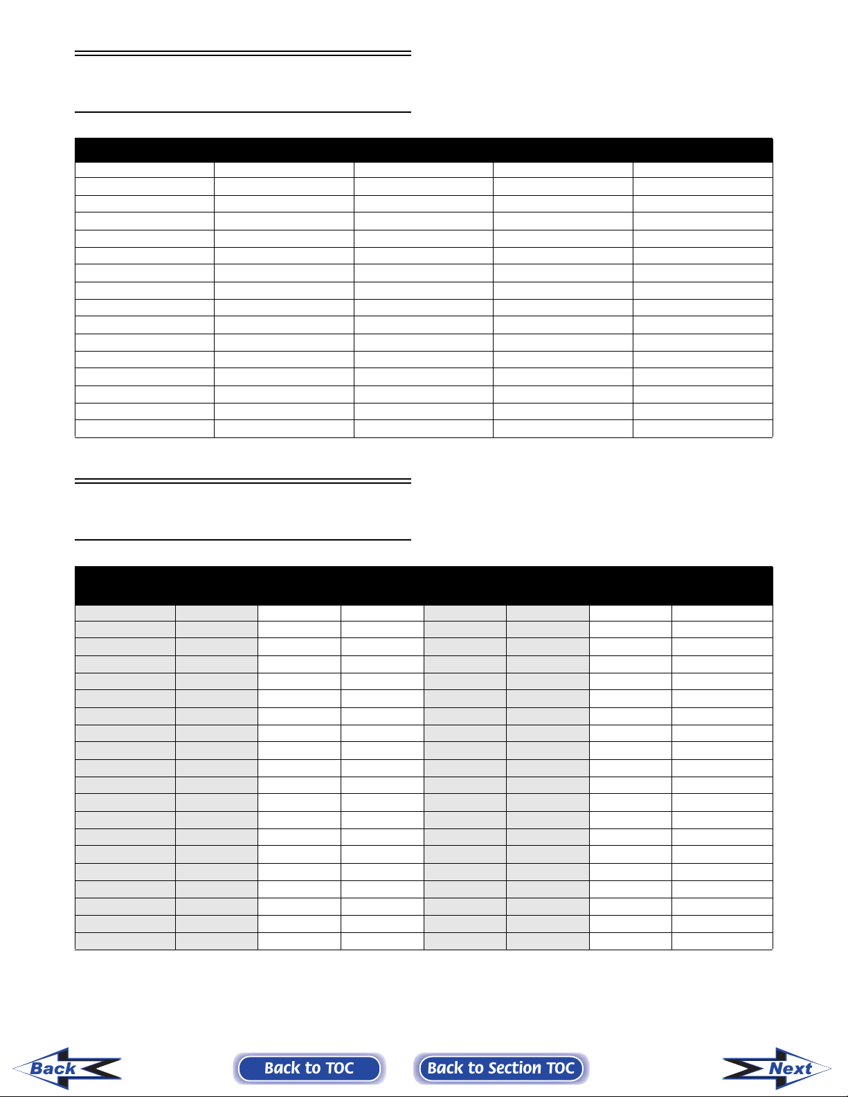
Torque Conversions
ft-lb kg-m ft-lb kg-m ft-lb kg-m ft-lb kg-m ft-lb kg-m
1 0.1212.941 5.7 61 8.4 81 11.2
2 0.3223.042 5.8 62 8.6 82 11.3
3 0.4233.243 5.8 63 8.7 83 11.5
4 0.6243.344 6.1 64 8.9 84 11.6
5 0.7253.545 6.2 65 9.0 85 11.8
6 0.8263.646 6.4 66 9.1 86 11.9
7 1.0273.747 6.5 67 9.3 87 12.0
8 1.1283.948 6.6 68 9.4 88 12.2
9 1.2294.049 6.8 69 9.5 89 12.3
10 1.4304.250 6.9 70 9.7 90 12.5
11 1.5314.351 7.1 71 9.8 91 12.6
12 1.7324.452 7.2 72 10.0 92 12.8
13 1.8334.653 7.3 73 10.1 93 12.9
14 1.9344.754 7.5 74 10.2 94 13.0
15 2.1354.855 7.6 75 10.4 95 13.1
16 2.2365.056 7.7 76 10.5 96 13.3
17 2.4375.157 7.9 77 10.7 97 13.4
18 2.5385.358 8.0 78 10.8 98 13.6
19 2.6395.459 8.2 79 10.9 99 13.7
20 2.8405.560 8.3 80 11.1 100 13.8
1
Tightening Torque
(General Bolts)
Typ e of Bo lt
(Conventional or
4 Marked Bolt)
(7 Marked Bolt) 5 0.3-0.6 2.0-4.5
Thread
Diameter
A (mm)
5 0.2-0.4 1.5-3.0
6 0.4-0.7 3.0-5.0
8 1.0-1.6 7.0-11.5
10 2.2-3.5 16.0-25.5
6 0.8-1.2 6.0-8.5
8 1.8-2.8 13.0-20.0
10 4.0-6.0 29.0-43.5
Tightening Torque
kg-m ft-lb
Back
Back to TOC
Back to Section TOC
1-7
Next
Fraction/Decimal
Conversion Chart
8ths 16ths 32nds 64ths 64ths (cont)
1/8 = .125 1/16 = .0625 1/32 = .03125 1/64 = .015625 33/64 = .515625
1/4 = .250 3/16 = .1875 3/32 = .09375 3/64 = .046875 35/64 = .546875
3/8 = .375 5/16 = .3125 5/32 = .15625 5/64 = .078125 37/64 = .578125
1/2 = .500 7/16 = .4375 7/32 = .21875 7/64 = .109375 39/64 = .609375
5/8 = .625 9/16 = .5625 9/32 = .28125 9/64 = .140625 41/64 = .640625
3/4 = .750 11/16 = .6875 11/32 = .34375 11/64 = .171875 43/64 = .671875
7/8 = .875 13/16 = .8125 13/32 = .40625 13/64 = .203125 45/64 = .703125
— 15/16 = .9375 15/32 = .46875 15/64 = .234370 47/64 = .734375
— — 17/32 = .53125 17/64 = .265625 49/64 = .765625
— — 19/32 = .59375 19/64 = .296875 51/64 = .796875
— — 21/32 = .65625 21/64 = .328125 53/64 = .828125
— — 23/32 = .71875 23/64 = .359375 55/64 = .859375
— — 25/32 = .78125 25/64 = .390625 57/64 = .890625
— — 27/32 = .84375 27/64 = .421875 59/64 = .921875
— — 29/32 = .90625 29/64 = .453125 61/64 = .953125
— — 31/32 = .96875 31/64 = .484375 63/64 = .984375
Drill Bit Sizes
(Number) Chart
No.
1 .2280 21 .1590 41 .0960 61 .0390
2 .2210 22 .1570 42 .0935 62 .0380
3 .2130 23 .1540 43 .0890 63 .0370
4 .2090 24 .1520 44 .0860 64 .0360
5 .2055 25 .1495 45 .0820 65 .0350
6 .2040 26 .1470 46 .0810 66 .0330
7 .2010 27 .1440 47 .0785 67 .0320
8 .1990 28 .1405 48 .0760 68 .0310
9 .1960 29 .1360 49 .0730 69 .0292
10 .1935 30 .1285 50 .0700 70 .0280
11 .1910 31 .1200 51 .0670 71 .0260
12 .1890 32 .1160 52 .0635 72 .0250
13 .1850 33 .1130 53 .0595 73 .0240
14 .1820 34 .1110 54 .0550 74 .0225
15 .1800 35 .1100 55 .0520 75 .0210
16 .1770 36 .1065 56 .0465 76 .0200
17 .1730 37 .1040 57 .0430 77 .0180
18 .1695 38 .1015 58 .0420 78 .0160
19 .1660 39 .0995 59 .0410 79 .0145
20 .1610 40 .0980 60 .0400 80 .0135
Size of Drill
in Inches
No.
Size of Drill
in Inches
No.
Size of Drill
in Inches
No.
Size of Drill in
Inches
Back
1-8
Back to TOC
Back to Section TOC
Next

MM/IN. Conversion
Chart
mm in. mm in. mm in. mm in. mm in.
.01 .00039 .41 .01614 .81 .03189 21 .82677 61 2.40157
.02 .00079 .42 .01654 .82 .03228 22 .86614 62 2.44094
.03 .00118 .43 .01693 .83 .03268 23 .90551 63 2.48031
.04 .00157 .44 .01732 .84 .03307 24 .94488 64 2.51968
.05 .00197 .45 .01772 .85 .03346 25 .98425 65 2.55905
.06 .00236 .46 .01811 .86 .03386 26 1.02362 66 2.59842
.07 .00276 .47 .01850 .87 .03425 27 1.06299 67 2.63779
.08 .00315 .48 .01890 .88 .03465 28 1.10236 68 2.67716
.09 .00354 .49 .01929 .89 .03504 29 1.14173 69 2.71653
.10 .00394 .50 .01969 .90 .03543 30 1.18110 70 2.75590
.11 .00433 .51 .02008 .91 .03583 31 1.22047 71 2.79527
.12 .00472 .52 .02047 .92 .03622 32 1.25984 72 2.83464
.13 .00512 .53 .02087 .93 .03661 33 1.29921 73 2.87401
.14 .00551 .54 .02126 .94 .03701 34 1.33858 74 2.91338
.15 .00591 .55 .02165 .95 .03740 35 1.37795 75 2.95275
.16 .00630 .56 .02205 .96 .03780 36 1.41732 76 2.99212
.17 .00669 .57 .02244 .97 .03819 37 1.45669 77 3.03149
.18 .00709 .58 .02283 .98 .03858 38 1.49606 78 3.07086
.19 .00748 .59 .02323 .99 .03898 39 1.53543 79 3.11023
.20 .00787 .60 .02362 1.0 .03937 40 1.57480 80 3.14960
.21 .00827 .61 .02402 1 .03937 41 1.61417 81 3.18897
.22 .00866 .62 .02441 2 .07874 42 1.65354 82 3.22834
.23 .00906 .63 .02480 3 .11811 43 1.69291 83 3.26771
.24 .00945 .64 .02520 4 .15748 44 1.73228 84 3.30708
.25 .00984 .65 .02559 5 .19685 45 1.77165 85 3.34645
.26 .01024 .66 .02598 6 .23622 46 1.81102 86 3.38582
.27 .01063 .67 .02638 7 .27559 47 1.85039 87 3.42519
.28 .01102 .68 .02677 8 .31496 48 1.88976 88 3.46456
.29 .01142 .69 .02717 9 .35433 49 1.92913 89 3.50393
.30 .01181 .70 .02756 10 .39370 50 1.96850 90 3.54330
.31 .01220 .71 .02795 11 .43307 51 2.00787 91 3.58267
.32 .01260 .72 .02835 12 .47244 52 2.04724 92 3.62204
.33 .01299 .73 .02874 13 .51181 53 2.08661 93 3.66141
.34 .01339 .74 .02913 14 .55118 54 2.12598 94 3.70078
.35 .01378 .75 .02953 15 .59055 55 2.16535 95 3.74015
.36 .01417 .76 .02992 16 .62992 56 2.20472 96 3.77952
.37 .01457 .77 .03032 17 .66929 57 2.24409 97 3.81889
.38 .01496 .78 .03071 18 .70866 58 2.28346 98 3.85826
.39 .01535 .79 .03110 19 .74803 59 2.32283 99 3.89763
.40 .01575 .80 .03150 20 .78740 60 2.36220 100 3.93700
1
Back
Back to TOC
Back to Section TOC
1-9
Next
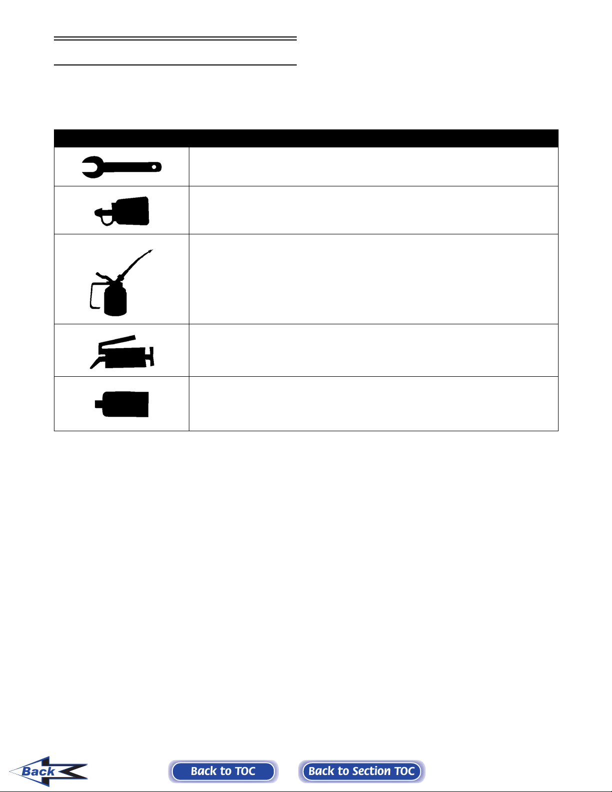
Servicing Symbols
Listed in the table below are symbols indicating special instructions and other important information necessary for
proper servicing. Please note the definition for each symbol. These symbols are used throughout this manual.
SYMBOL DESCRIPTION
Torque control required
243 - apply blue Loctite #243 (p/n 1639-413)
270 - apply green Loctite #270 (p/n 1639-817)
271 - apply red Loctite #271 (p/n 1639-820)
609 - apply green Loctite #609 (p/n 1639-821)
Lubricate with Arctic Cat 50:1 Injection Oil (p/n 0636-286) - Non-APV Engines
Lubricate with Arctic Cat Synthetic APV 2-Cycle Oil (p/n 2639-512) - APV Engines
Lubricate with Arctic Cat Low-Temp Grease (p/n 0636-593)
3B - Three Bond Sealant (p/n 0636-070)
HT - High-Temp Sealant (p/n 0636-069)
AS - Anti-Seize Thread Compound (p/n 0678-146)
Back
1-10
Back to TOC
Back to Section TOC

SECTION 2 - ENGINE
2
TABLE OF
CONTENTS
Arctic Cat Engine Specifications ............................. 2-2
Torque Conversions ................................................ 2-3
Piston Replacement Guide ..................................... 2-3
Assembly Schematics (Table of Contents) .............. 2-4
Engine Piston Travel Versus Crank Angle Chart ... 2-18
Crankshaft Runout/Repair Specifications ............. 2-19
Cylinder Head Volume Specifications ................... 2-20
Engine ................................................................... 2-20
Removing Engine (Table of Contents)................... 2-20
Disassembling Engine (Table of Contents) ........... 2-29
Servicing Top-Side Components
(500/600/700 cc Models) ................................... 2-50
Cleaning and Inspecting Engine ........................... 2-53
Measuring Critical Components ............................ 2-58
Assembling Engine (Table of Contents) ................ 2-61
Installing Engine (Table of Contents)..................... 2-85
Troubleshooting Engine (Carbureted Models) ....... 2-96
Troubleshooting Engine (EFI Models) ................... 2-99
Back to TOC
2-1

862
698
698
599
565
52.6
42.59
42.59
36.54
34.5
85
3.346
79.7
3.145
79.7
3.145
73.8
2.906
73.8
2.910
76
70
70
70
66
2.992
2.755
2.755
2.755
2.598
23f*
12j*
12i*
15d*
18e*
3.775
0.149
0.969
0.038
0.969
0.038
1.509
0.059
2.049
0.081
0.7-0.8
0.028-0.031
0.7-0.8
0.028-0.031
0.7-0.8
0.028-0.031
0.7-0.8
0.028-0.031
0.7-0.8
0.028-0.031
0.30-0.50
0.012-0.020
0.075-0.105
0.0029-0.0041
0.30-0.50
0.012-0.0196
0.075-0.105
0.0029-0.0041
0.30-0.50
0.012-0.0196
0.075-0.105
0.0029-0.0041
0.30-0.50
0.012-0.0196
0.075-0.105
0.0029-0.0041
0.20-0.83
0.008-0.033
0.095-0.150
0.0037-0.0059
23.995-24.000
0.1
0.004
21.995-22.000
0.1
0.004
21.995-22.000
0.1
0.004
21.995-22.000
0.1
0.004
17.995-18.000
0.1
0.004
24.002-24.010
0.9450-0.9453
0.9447-0.9449
0.8659-0.8661
0.8659-0.8661
0.8659-0.8661
0.7085-0.7087
29.003-29.011
1.1410-1.1420
22.002-22.010
0.8662-0.8665
27.003-27.011
1.0631-1.0634
22.002-22.010
0.8662-0.8665
27.003-27.011
1.0631-1.0634
22.002-22.010
0.8662-0.8665
27.003-27.011
1.0631-1.0634
17.998-18.006
0.7086-0.7089
23.003-23.011
0.9056-0.9059
0.05
0.002
0.003-0.020
0.0001-0.0008
0.05
0.002
0.003-0.020
0.0001-0.0007
0.05
0.002
0.003-0.020
0.0001-0.0007
0.05
0.002
0.003-0.020
0.0001-0.0007
0.05
0.002
0.02-0.03
0.0008-0.0012
11.0
0.05-0.10
0.002-0.004
11.0
0.05-0.10
0.002-0.004
11.0
0.05-0.10
0.002-0.004
11.0
0.05-0.10
0.002-0.004
6.0
0.05-0.10
0.002-0.004
0.433
0.433
0.433
0.433
0.236
499
499
431
30.4
30.4
26.3
71
65
2.795
2.795
2.559
63
63
65
2.480
2.480
2.559
30e*
16e*
18e*
5.258
1.535
2.012
0.207
0.060
0.079
0.7-0.8
0.028-0.031
0.7-0.8
0.028-0.031
0.7-0.8
0.028-0.031
0.20-0.40
0.008-0.016
0.075-0.105
0.0029-0.0041
0.20-0.40
0.008-0.016
0.075-0.105
0.0029-0.0041
9
0.15-0.83
0.006-0.033
0.0031-0.005
0.080-0.150
71
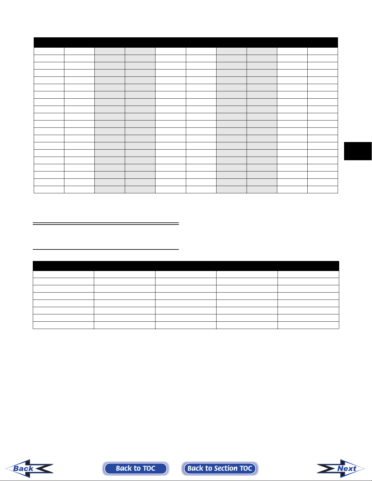
Arctic Cat Engine Specifications
60
367
22.41
— cu in.
2.362
— in.
65
— mm
2.559
— in.
18e*
2.012
0.079
— mm
— in.
0.7-0.8
0.028-0.031
— in.
0.060-0.150
0.15-0.80
0.006-0.031
0.0024-0.0059
— mm
— in.
— in.
21.995-22.000
0.1
0.004
21.995-22.000
0.1
0.004
15.995-16.000
0.1
0.004
17.995-18.000
0.1
0.004
— in.
22.002-22.010
0.8662-0.8665
0.8659-0.8661
0.8659-0.8661
0.6297-0.6299
0.7085-0.7087
— in.
27.003-27.011
1.0631-1.0634
22.002-22.010
0.8662-0.8665
27.003-27.011
1.0631-1.0634
03-21.011
15.996-16.004
0.6298-0.6301
0.8269-0.8272
21.0
17.998-18.006
0.7086-0.7089
23.003-23.011
0.9056-0.9059
— mm
— in.
— mm
— in.
0.05
0.002
0.003-0.020
0.0001-0.0007
0.05
0.002
0.003-0.020
0.0001-0.0007
0.05
0.002
0.02-0.03
0.0008-0.0012
0.05
0.002
0.02-0.03
0.0008-0.0012
— in.
— mm
— in.
8.0
0.05-0.10
0.002-0.004
0.05-0.10
0.002-0.004
0.05-0.10
0.002-0.004
N/A N/A 8.0
0.05-0.10
0.002-0.004
— in.
0.315
0.315
— in.
2-2
ITEM 370 cc 440 cc 500 cc EFI 500 cc Carb 570 cc 600 cc EFI 700 cc Carb 700 cc EFI 900 cc EFI
Engine Model Number AA37A8 AS44A9 AX50L5 AV50L5 AA56A5 AJ60L3 AE70L4 AD70L4 AB86L5
D is p la c em e n t — c c
d @ 1800 RPM h @ 3500 RPM
e @ 2000 RPM i @ 4000 RPM
c @ 1400 RPM g @ 3200 RPM
f @ 2500 RPM j @ 4350 RPM
*Engine Warm
Connecting Rod Small End
Stroke
Bore — mm
No. of Cylinders 2 2 2 2 2 2 2 2 2
Back to TOC
Compression Ratio 6.3:1 6.5:1 6.34:1 6.30:1 6.4:1 6.46:1 6.49:1 6.49:1 6.41:1
Cooling System Fan Cooled Fan Cooled Liquid Cooled Liquid Cooled Fan Cooled Liquid Cooled Liquid Cooled Liquid Cooled Liquid Cooled
Gasoline Octane (min) 87 87 87 87 87 87 87 87 87
Fuel Mixture Oil Injection Oil Injection Oil Injection Oil Injection Oil Injection Oil Injection Oil Injection Oil Injection Oil Injection
Ignition Timing degrees
Lighting Coil Output 12V/185W 12V/185W 12V/156W 12V/156W 12V/210W 12V/190W 12V/156W 12V/190W 12V/190W
Ignition Type CDI/NOI CDI/NOI CDI/NOI CDI/NOI CDI/NOI CD/NOI CDI/NOI CDI/NOI CDI/NOI
Piston Skirt/Cylinder
Spark Plug (NGK) BR9EYA BR9EYA BR9EYA BR9EYA BR9EYA BR9EYA BR9EYA BR9EYA BR9EYA
Spark Plug Gap — mm
Clearance Range
Back to Section TOC
Piston Ring End Gap Range — mm
Cylinder Trueness Limit (max) — mm
Piston Pin Diameter Range — mm
Piston Pin Bore Diameter
Range
Bore Diameter Range
Connecting Rod Radial Play
Crankshaft Runout (t.i.r.) — mm
Range
Crankshaft End Play Range — mm
Reed Stopper Height — mm
Next
Torque Conversions
ft-lb kg-m ft-lb kg-m ft-lb kg-m ft-lb kg-m ft-lb kg-m
10.121 2.9415.761 8.4 81 11.2
20.3
30.4
40.6
50.7
60.8
71.0
81.1
91.2
10 1.4
11 1.5
12 1.7
13 1.8
14 1.9
15 2.1
16 2.2
17 2.4
18 2.5
19 2.6
20 2.8
22 3.0425.862 8.6 82 11.3
23 3.2435.863 8.7 83 11.5
24 3.3446.164 8.9 84 11.6
25 3.5456.265 9.0 85 11.8
26 3.6466.466 9.1 86 11.9
27 3.7476.567 9.3 87 12.0
28 3.9486.668 9.4 88 12.2
29 4.0496.869 9.5 89 12.3
30 4.2506.970 9.7 90 12.5
31 4.3517.171 9.8 91 12.6
32 4.4527.272 10.0 92 12.8
33 4.6537.373 10.1 92 12.9
34 4.7547.574 10.2 94 13.0
35 4.8557.675 10.4 95 13.1
36 5.0567.776 10.5 96 13.3
37 5.1577.977 10.7 97 13.4
38 5.3588.078 10.8 98 13.6
39 5.4598.279 10.9 99 13.7
40 5.5608.380 11.1 100 13.8
2
Piston Replacement
Guide
ENGINE SIZE YEAR PISTON RING PISTON & RING SET
370 cc 2006 * 3004-825 3005-913
440 cc 2006 * 3006-413 3005-920
500 cc w/APV 2006 * 3005-828 3006-427
500 cc w/o APV 2006 * 3005-828 3006-746
570 cc 2006 * 3006-004 3006-528
600 cc 2006 * 3006-004 3006-645
900 cc 2006 * 3006-394 3006-393
700 cc 2006 * 3006-500 3006-499
* Not a Service Part
Back
Back to TOC
Back to Section TOC
2-3
Next
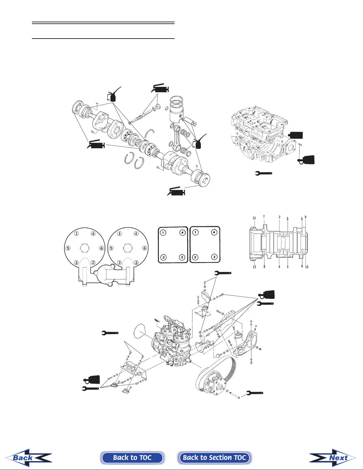
Assembly Schematics
Table of Contents
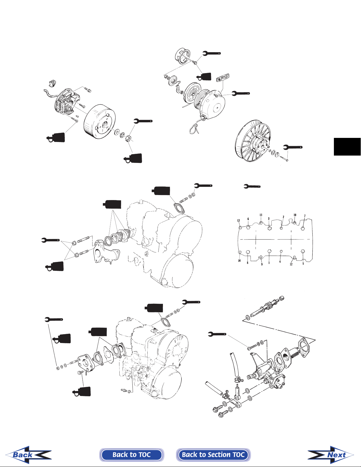
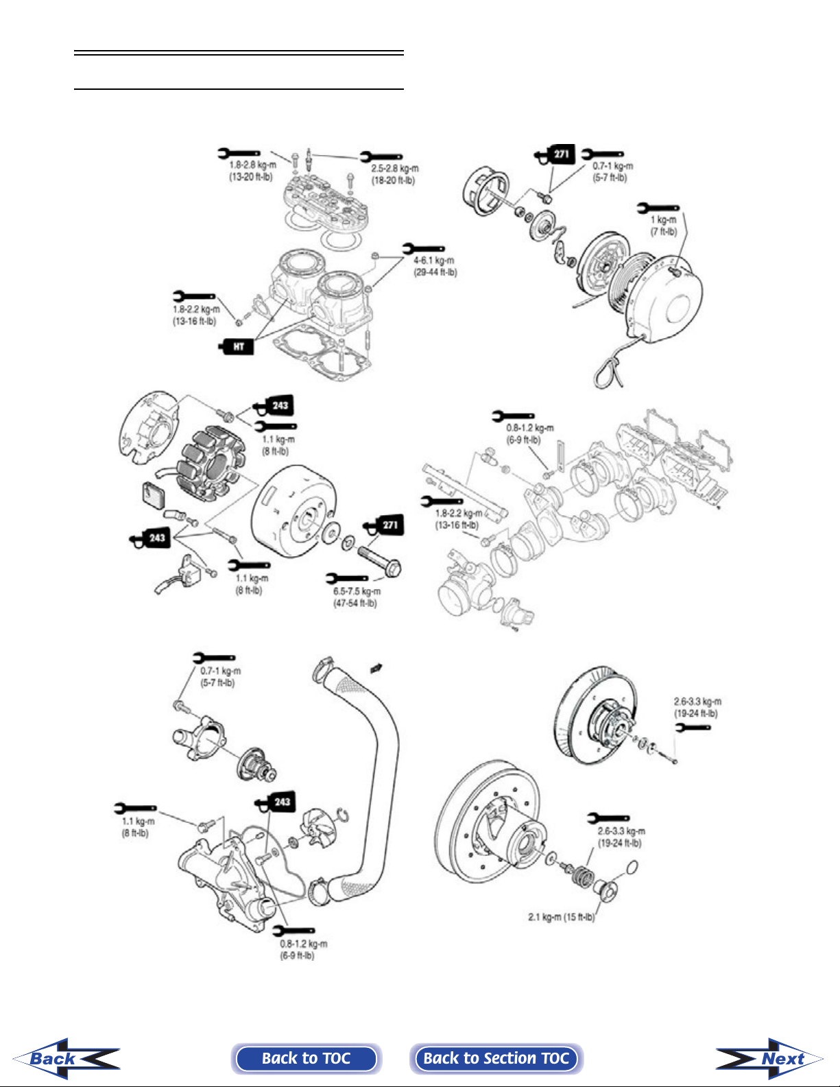
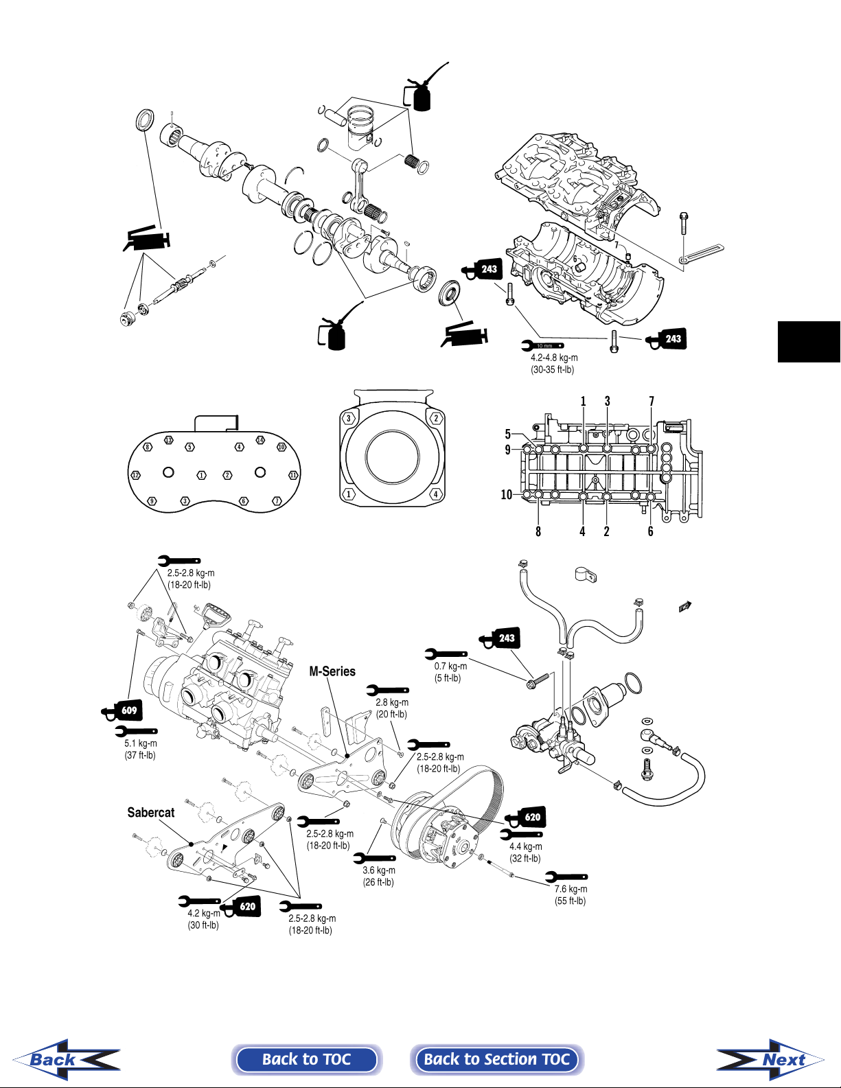
370/440 cc ............................................................. 2-6
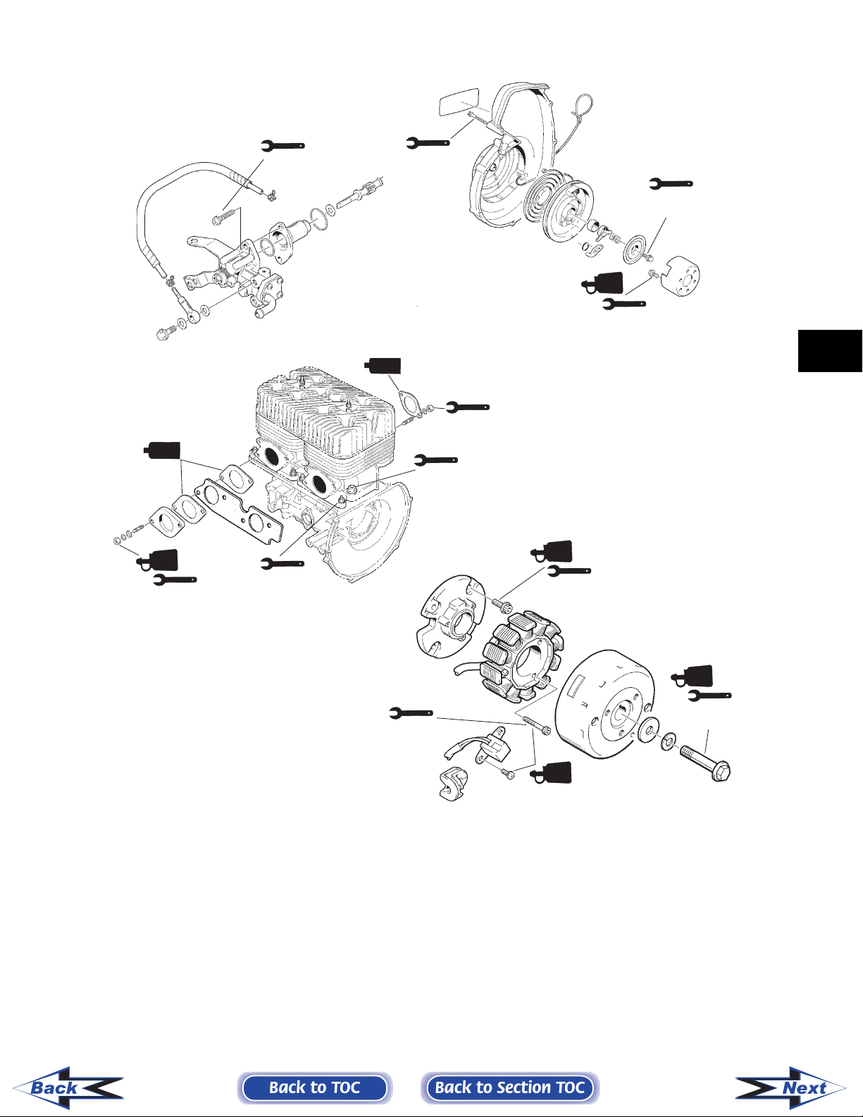
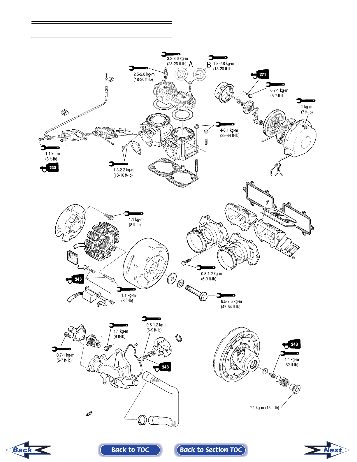
570 cc ..................................................................... 2-8
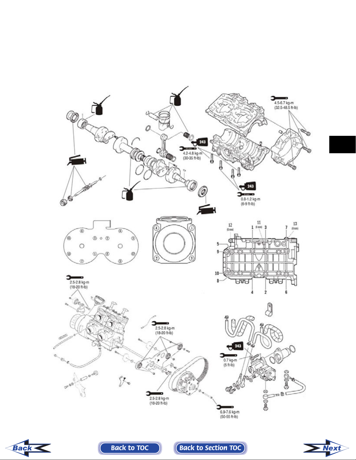
900 cc ................................................................... 2-10
500 cc (Carb) ........................................................ 2-12
500 cc EFI............................................................. 2-14
600/700 cc ........................................................... 2-16
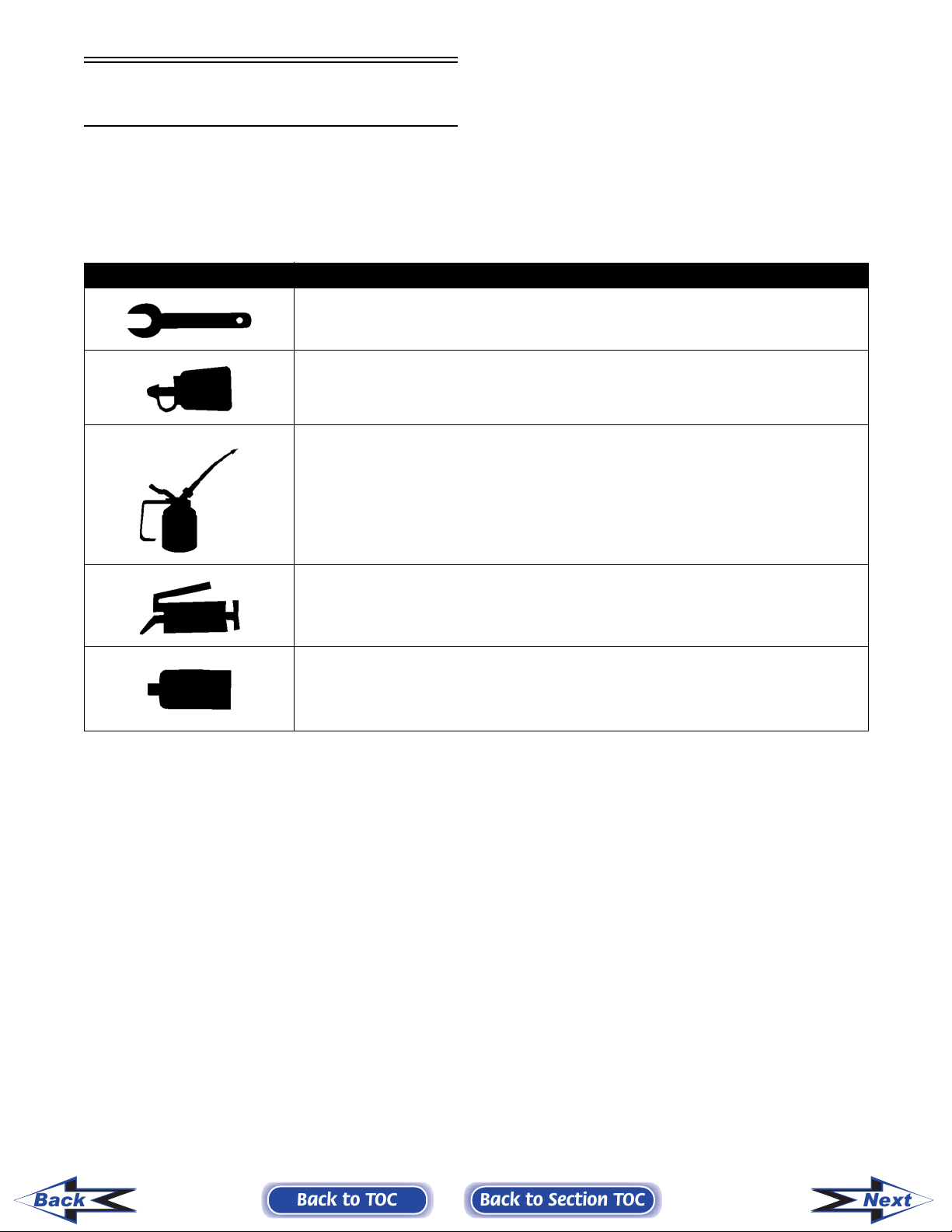
SYMBOL DESCRIPTION
Torque control required
243 - apply blue Loctite #243 (p/n 1639-413)
270 - apply green Loctite #270 (p/n 1639-817)
271 - apply red Loctite #271 (p/n 1639-820)
609 - apply green Loctite #609 (p/n 1639-821)
Lubricate with Arctic Cat 50:1 Injection Oil (p/n 0636-286) - Non-APV Engines
Lubricate with Arctic Cat Synthetic APV 2-Cycle Oil (p/n 2639-512) - APV Engines
Listed in the table below are symbols indicating special instructions and other important information
necessary for proper servicing. Please note the definition for each symbol. These symbols are used
throughout this manual.
Lubricate with Arctic Cat Low-Temp Grease (p/n 0636-593)
3B - Three Bond Sealant (p/n 0636-070)
HT - High-Temp Sealant (p/n 0636-069)
AS - Anti-Seize Thread Compound (p/n 0678-146)
Back
2-4
Back to TOC
Back to Section TOC
Next
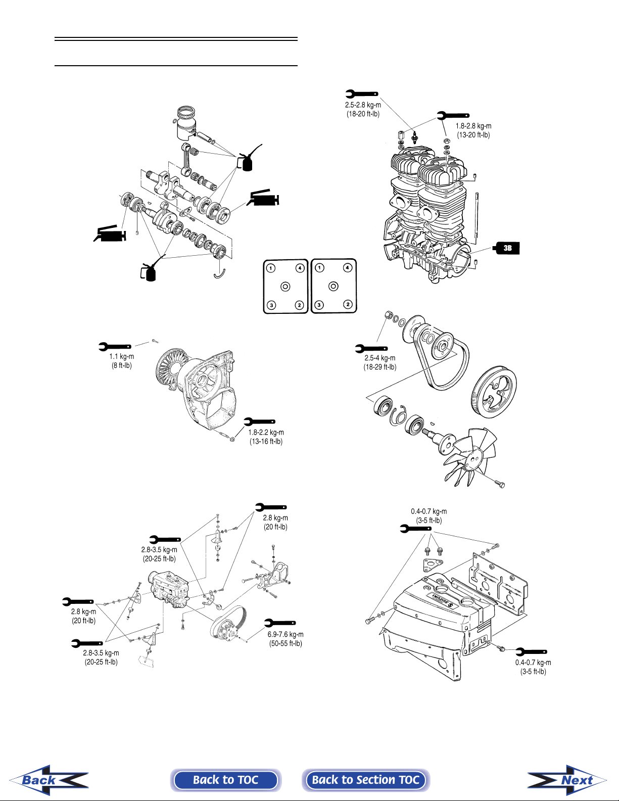
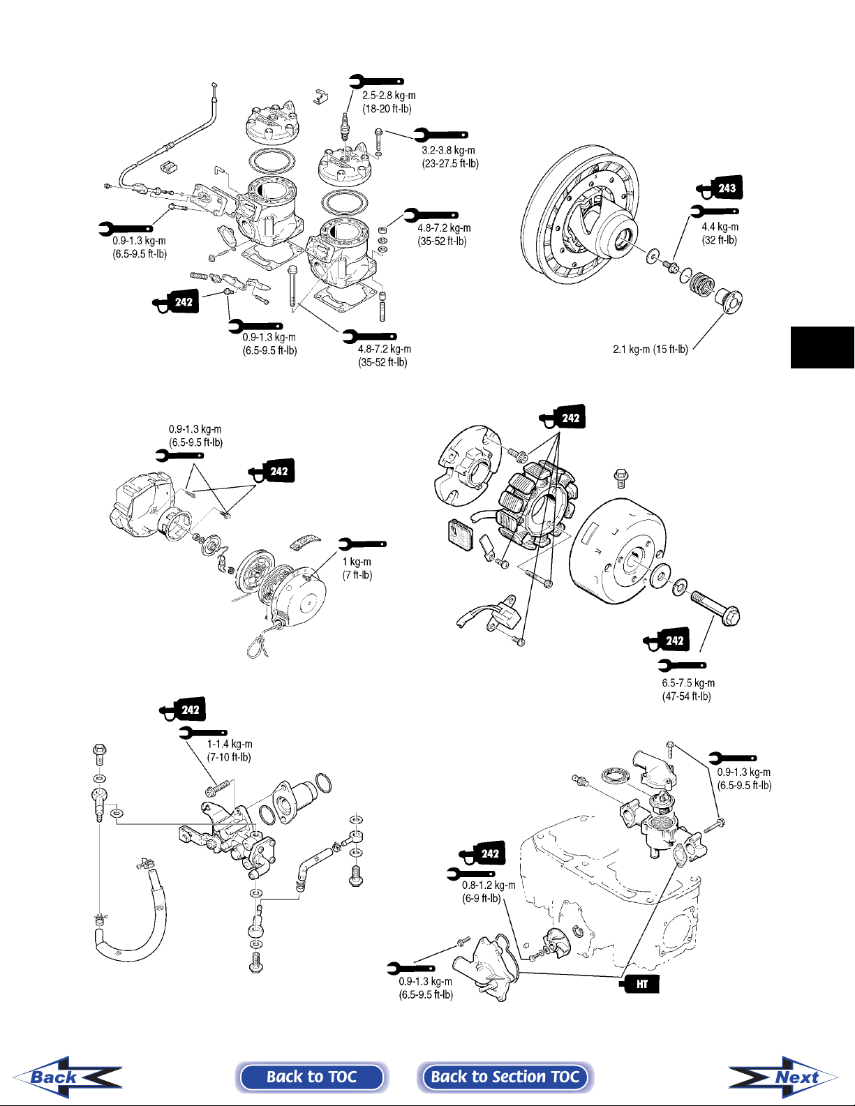
370/440 cc
Back
2-6
Back to TOC
Back to Section TOC
3744-ENG05
Next
271
0.8-1.2 kg-m
(6-9 ft-lb)
271
1.1 kg-m
(8 ft-lb)
7-9 kg-m
(50.5-65 ft-lb)
1.8-2.2 kg-m
(13-16 ft-lb)
271
2.6-3.3 kg-m
271
HT
HT
HT
1.8-2.2 kg-m
(13-16 ft-lb)
1.8-2.2 kg-m
(13-16 ft-lb)
6 mm 0.8-1.2 kg-m
(6-9 ft-lb)
8 mm 1.8-2.8 kg-m
(13-20 ft-lb)
(19-24 ft-lb)
2
Back
1.8-2.2 kg-m
(13-16 ft-lb)
271
271
HT
Back to TOC
0.7 kg-m
(5 ft-lb)
Back to Section TOC
3744ENG2
2-7
Next
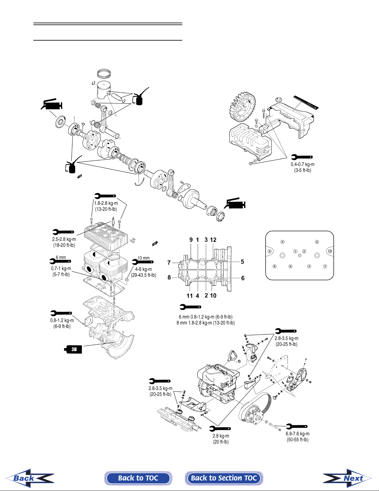
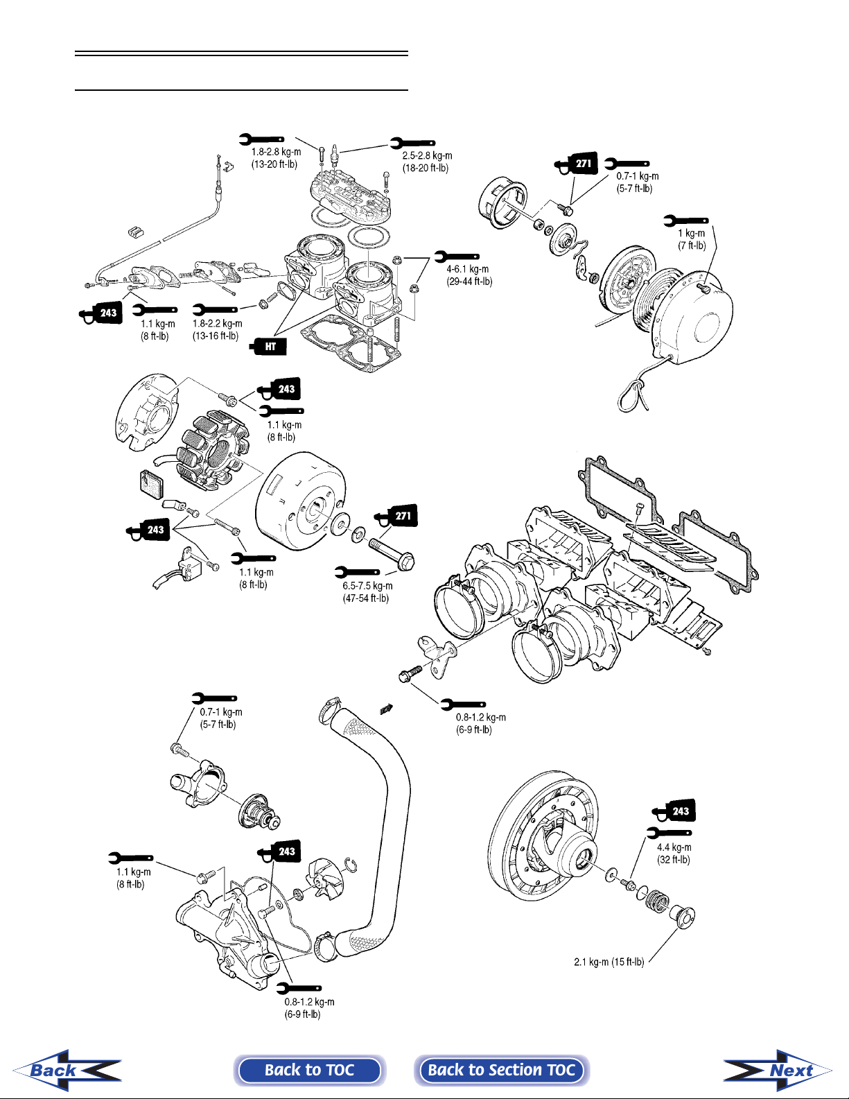
570 cc
Back
2-8
Back to TOC
Back to Section TOC
570-ENG05
Next
HT
1.1 kg-m
(8 ft-lb)
1.8-2.2 kg-m
(13-16 ft-lb)
4-6 kg-m
(29-43.5 ft-lb)
0.8-2.1 kg-m
(6-9 ft-lb)
609*
1.8-2.8 kg-m
(13-20 ft-lb)
*Must be used in conjunction
with Loctite Primer #7471.
2
0.8-1.2 kg-m
(6-9 ft-lb)
HT
271
1.8-2.2 kg-m
(13-16 ft-lb)
0.7-1.0 kg-m
(5-7 ft-lb)
0.8-1.2 kg-m
(6-9 ft-lb)
271
0.8-1.2 kg-m
(6-9 ft-lb)
271
8-8.7 kg-m
(58-63 ft-lb)
271
Back
Back to TOC
Back to Section TOC
570ENG
2-9
Next
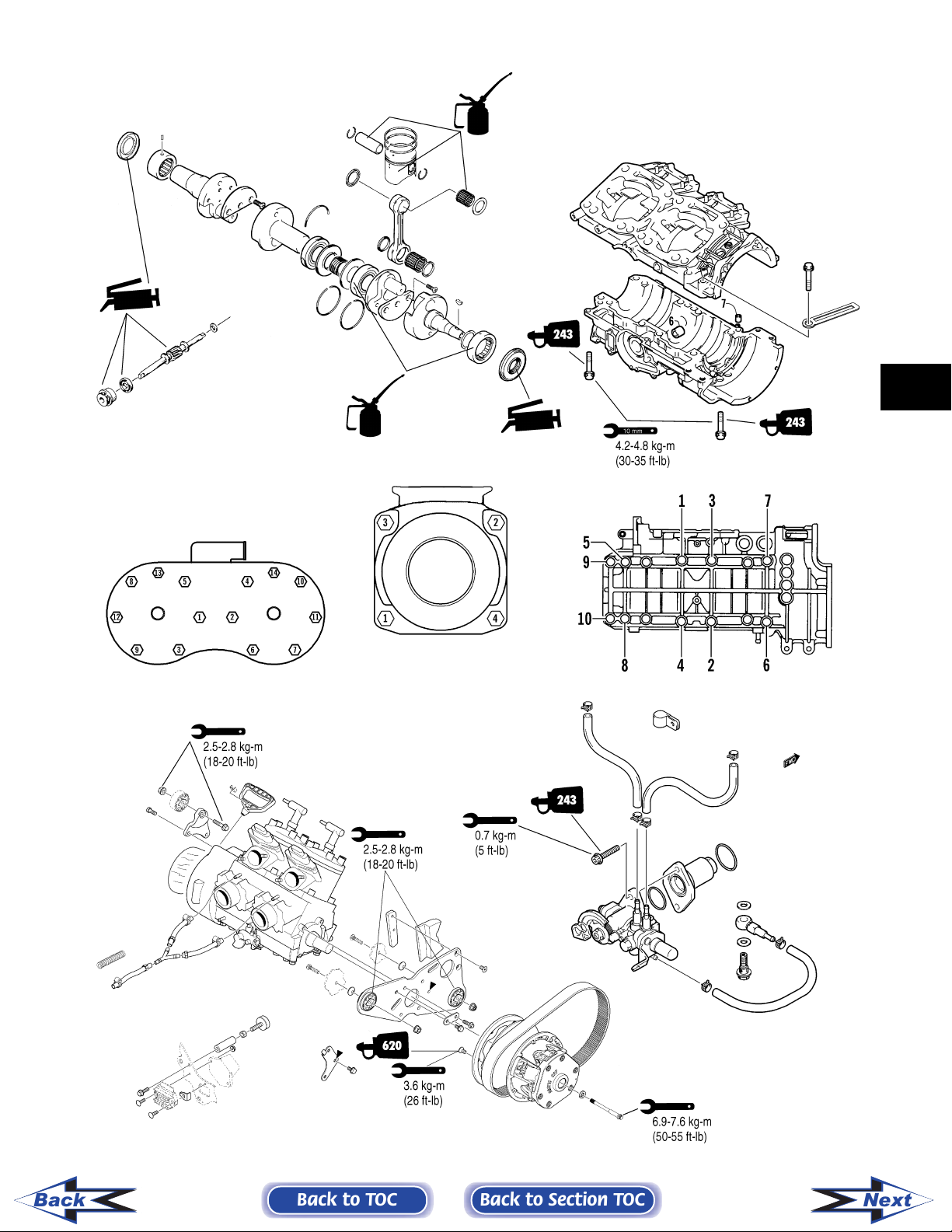
900 cc
10 mm
4.2-4.8 kg-m
(30-35 ft-lb)
6 mm 0.8-1.2 kg-m
(6-9 ft-lb)
HT
243
243
2.4 kg-m
(17 ft-lb)
2.8-3.5 kg-m
(20-25 ft-lb)
2.8-3.5 kg-m
(20-25 ft-lb)
2.4 kg-m
(17 ft-lb)
6.9-7.6 kg-m
(50-55 ft-lb)
243
900-ENG
Back
2-10
Back to TOC
Back to Section TOC
Next
2
Back
Back to TOC
Back to Section TOC
900-ENG2A
2-11
Next
500 cc (Carb)
Back
2-12
Back to TOC
Back to Section TOC
500CC1C
Next
2
Back
Back to TOC
Back to Section TOC
500CC5A
2-13
Next
500 cc EFI
Back
2-14
Back to TOC
Back to Section TOC
500CC1A
Next
2
Back
Back to TOC
Back to Section TOC
500CC2A_05
2-15
Next
600/700 cc
Back
2-16
Back to TOC
Back to Section TOC
700CC1B
Next
2
Back
Back to TOC
Back to Section TOC
700CC2A
2-17
Next
Back
the degree figure to find timing in either mm or inches.
Engine Piston Travel Versus Crank Angle Chart
500 cc 600/700 cc 370 cc - 440 cc 570 cc 900 cc
63 mm stroke 70 mm stroke 65 mm stroke 66 mm stroke 76 mm stroke
mm BTDC in. BTDC mm BTDC in. BTDC mm BTDC in. BTDC mm BTDC in. BTDC mm BTDC in. BTDC
5 0.151 0.006 0.169 0.007 0.157 0.006 0.160 0.006 0.182 0.007
6 0.218 0.009 0.243 0.009 0.226 0.009 0.230 0.009 0.262 0.010
7 0.296 0.012 0.331 0.013 0.308 0.012 0.313 0.012 0.356 0.014
8 0.387 0.015 0.432 0.017 0.402 0.016 0.409 0.016 0.465 0.018
9 0.489 0.019 0.546 0.021 0.508 0.020 0.517 0.020 0.588 0.023
10 0.603 0.024 0.674 0.026 0.627 0.025 0.638 0.025 0.726 0.029
11 0.729 0.029 0.815 0.032 0.757 0.030 0.772 0.030 0.878 0.035
12 0.867 0.034 0.969 0.038 0.901 0.035 0.917 0.036 1.044 0.041
13 1.017 0.040 1.136 0.045 1.056 0.042 1.076 0.042 1.224 0.048
14 1.178 0.046 1.316 0.052 1.223 0.048 1.246 0.049 1.417 0.056
15 1.351 0.053 1.509 0.059 1.403 0.055 1.429 0.056 1.625 0.064
16 1.535 0.060 1.714 0.067 1.594 0.063 1.624 0.064 1.847 0.073
17 1.730 0.068 1.933 0.076 1.797 0.071 1.830 0.072 2.082 0.082
18 1.937 0.076 2.164 0.085 2.012 0.079 2.049 0.081 2.331 0.089
19 2.155 0.085 2.407 0.095 2.238 0.088 2.280 0.090 2.594 0.102
20 2.384 0.094 2.663 0.105 2.476 0.097 2.522 0.099 2.869 0.113
21 2.624 0.103 2.931 0.115 2.725 0.107 2.776 0.109 3.158 0.124
22 2.875 0.113 3.211 .0126 2.986 0.118 3.041 0.120 3.460 0.136
23 3.137 0.124 3.504 0.138 3.257 0.128 3.318 0.131 3.775 0.149
24 3.409 0.134 3.808 0.150 3.540 0.139 3.606 0.142 4.103 0.162
25 3.692 0.145 4.123 0.162 3.834 0.151 3.905 0.154 4.443 0.175
26 3.985 0.156 4.451 0.175 4.138 0.163 4.215 0.166 4.796 0.189
27 4.288 0.169 4.790 0.188 4.453 0.175 4.536 0.179 5.161 0.203
28 4.602 0.181 5.139 0.202 4.778 0.188 4.867 0.192 5.538 0.218
29 4.925 0.194 5.500 0.216 5.114 0.201 5.209 0.205 5.927 0.233
30 5.258 0.207 5.872 0.231 5.459 0.215 5.561 0.219 6.328 0.249
31 5.601 0.220 - - 5.815 0.229 5.923 0.233 - -
2-18
When using any of the charts below, first know the engine stroke and timing in degrees; then select the proper chart and read across from
BTDC
Degree
Back to TOC
Back to Section TOC
32 - - - - 6.181 0.243 6.295 0.248 - -
33 - - - - 6.556 0.258 6.677 0.263 - -
Next
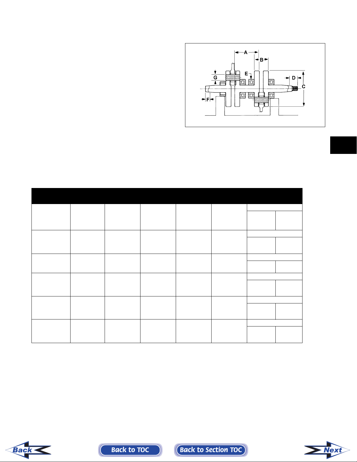
Crankshaft Runout/Repair Specifications
For those who have crankshaft work sent out to
another shop, it is advisable to provide them with
this information.
To use the specifications, first refer to the drawing;
then find the letter which indicates the specification
and refer to the chart below the illustration. Be sure
to note the proper engine column. Specifications are
called out in both millimeters and inches.
NOTE: We have given the proper location for
checking crankshaft runout as the very edge of the
straight portion of the shaft where the oil seal
makes contact. From the illustration, note that Arctic Cat has called out three check points: at either
end, out on the taper as shown, and also on the
center bearing race. The crankshaft is still supported on the outer bearings using V blocks. The
maximum runout shouldn’t exceed 0.05 mm (0.002
in.).
728-144A
2
Engine
370 cc
440 cc mm
500 cc
570 cc
600 cc
700 cc
900 cc
(in.)
mm
(in.)
mm
(in.)
mm
(in.)
mm
(in.)
mm
(in.)
Bore X
Stroke
60 X 65 (± .002)
65 X 65 100 ± 0.15
71 X 63 114.7 ± 0.15
73.8 X 66 119 ± 0.15
73.8 X 70 119.7 ± 0.15
79.7 X 70 119.7 ± 0.15
85 X 76 125.5 ± 0.15
A B C G Runout D, E, F Point
(3.937 ±
0.006)
(4.515 ±
0.006)
(4.70 ± 0.006)
(4.712 ±
0.006)
(4.712 ±
0.006)
(4.94 ± 0.006)
55 ± 0.15
(2.165 ±
0.006)
66.5 ± 0.15
(2.618 ±
0.006)
62.3 ± 0.15
(2.45 ± 0.006)
64 ± 0.15
(2.519 ±
0.006)
64 ± 0.15
(2.519 ±
0.006)
68 ± 0.15
(2.68 ± 0.006)
100
(3.937)
106 ± 0.4
(4.465 ±
0.015)
109.7
(4.320)
118 ± 0.4
(4.645 ±
0.015)
118 ± 0.4
(4.645 ±
0.015)
123 + 0-0.4
(4.84 + 0-
0.015)
22
(0.866)
27
(1.062)
24
(0.945)
30
(1.181)
30
(1.181)
30
(1.2)
D 35
(1.377)
D 5
(0.196)
D 30
(1.181)
D 5
(0.196)
D 5
(0.196)
D 30
(1.181)
(± .002)
(± .002)
(± .002)
(± .002)
(± .002)
F 22
(0.866)
F 5
(0.197)
F 15
(0.590)
F 5
(0.196)
F 5
(0.196)
F 15
(0.590)
NOTE: Measure in from the shaft end the specified amount when checking runout at points D-F. When
checking runout in the center, place indicator on center of bearing as shown at Point E. Maximum runout at
any of the 3 measuring points is ±0.05 mm (0.002 in.).
Back
Back to TOC
Back to Section TOC
2-19
Next
 Loading...