

Arctic Cat SD-ROM 2002 Service Manual

TABLE OF
CONTENTS
Section
1. General Information (Vol. I)
2. Engine (Vol. I)
3. Engine-Related Items (Vol. I)
4. Fuel Systems (Vol. I)
Click on the red text to go.
5. Engine Electrical Systems (Vol. I)
6. Chassis Electrical Systems (Vol. II)
7. Steering and Body (Vol. II)
8. Drive Train and Brake Systems (Vol. II)
9. Track/Rear Suspension (Vol. II)

SECTION 1 — GENERAL INFORMATION
1
Snowmobile Identification ....................................... 1-2
Recommended Gasoline and Oil ........................... 1-2
Break-In Procedure ................................................ 1-3
Genuine Parts ........................................................ 1-3
High Altitude Operation .......................................... 1-4
Drive Chain Lubrication (120 cc) ............................ 1-4
Preparation For Storage ......................................... 1-4
Preparation After Storage ....................................... 1-6
After Break-In Checkup (100 Miles) ....................... 1-6
After Break-In Checkup Checklist .......................... 1-7
Torque Conversions ............................................... 1-8
Tightening Torque (General Bolts) ........................ 1-8
Fraction/Decimal Conversion Chart ....................... 1-9
Drill Bit Sizes (Number) Chart ................................ 1-9
MM/In. Conversion Chart ..................................... 1-10
Servicing Symbols ................................................ 1-11
Back to TOC
TABLE OF
CONTENTS
1-1

Snowmobile
Identification
The Arctic Cat Snowmobile has two important identification numbers. The Vehicle Identification Number (VIN)
is stamped into the tunnel near the right-side footrest. The
Engine Serial Number (ESN) is stamped into the crankcase of the engine.
RECOMMENDED GASOLINE
(EFI Models)
The recommended gasoline to use in these snowmobiles
is 87 minimum octane regular unleaded, and the Fuel
Designation Connector at the ECU must be connected. In
many areas, oxygenates (either ethanol or MTBE) are
added to the gasoline. Oxygenated gasolines containing
up to 10% ethanol or up to 15% MTBE are acceptable
gasolines; however, if oxygenated gasoline is used, the
Fuel Designation Connector at the ECU must be disconnected. Do not use gasolines containing methanol.
0726-383
These numbers are required to complete warranty claims
properly. No warranty will be allowed by Arctic Cat Inc.
if the engine serial number or VIN is removed or mutilated in any way.
Recommended
Gasoline and Oil
RECOMMENDED GASOLINE
(Carbureted Models)
The recommended gasoline to use in these snowmobiles is 87 minimum octane regular unleaded. In many
areas, oxygenates (either ethanol or MTBE) are added
to the gasoline. Oxygenated gasolines containing up to
10% ethanol or up to 15% MTBE are acceptable gasolines; however, whenever using oxygenated gasolines,
the carburetor main jet must be one size larger than the
main jet required for regular unleaded gasoline. For
example, if a 400 main jet is recommended for regular
unleaded gasoline, a 410 main jet must be installed if
using an oxygenated gasoline.
When using ethanol blended gasoline, it is not necessary
to add a gasoline antifreeze since ethanol will prevent the
accumulation of moisture in the fuel system.
734-482A
! CAUTION
Do not use white gas or gasoline containing
methanol. Only Arctic Cat approved gasoline
additives should be used.
! CAUTION
If oxygenated gasoline is to be used, it is
extremely important that the Fuel Designation
Connector at the ECU is disconnected. If the
connector is not disconnected when using
oxygenated gasoline, severe engine damage
may occur.
NOTE: In order for the ECU to change modes, the
engine must be OFF when connecting or disconnecting the Fuel Designation Connector.
RECOMMENDED OIL
(Oil-Injection System)
The recommended oil to use in the oil-injection system is
Arctic Cat 50:1 Injection Oil (for standard models) or
Arctic Cat Synthetic APV 2-Cycle Oil (for APV models).
The oil is specially formulated to be used either as an
injection oil or as a pre-mix oil (for carbureted model
break-in) and meets all of the lubrication requirements of
the Arctic Cat snowmobile engine.
! CAUTION
Do not use white gas or gasolines containing
methanol. Only Arctic Cat approved gasoline
additives should be used.
1-2
Back to TOC
Back to Section TOC
Next
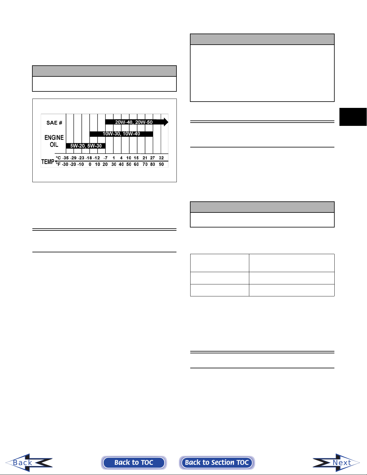
RECOMMENDED OIL
(4-Stroke Model)
The recommended oil to use is a multi-grade oil calibrated to the ambient temperature at which the engine is
run. See the viscosity chart for details.
! CAUTION
Any oil used in place of the recommended oil
may cause serious damage.
Multi-Grade
! CAUTION
DO NOT exceed the one (1) tankful limitation of a
100:1 gas/oil break-in mixture. Continuous use of
a gas/oil mixture, unless consistently operating
in extremely cold conditions (-26°C/-15°F or
colder), could cause spark plug fouling and
excessive carbon buildup. A 100:1 gas/oil
mixture must be used in conjunction with the oilinjection system to ensure adequate engine
lubrication in extremely cold conditions.
1
Break-In Procedure
(4-Stroke Model)
The Arctic Cat 4-stroke engine (when new or rebuilt)
requires a short break-in period before the engine is subjected to heavy load conditions.
GEN-0048
After the engine break-in period, the engine oil should be
changed every 3500 miles (on the 4-Stroke Touring and
Trail) and before prolonged storage.
Break-In Procedure
(2-Stroke Models)
The Arctic Cat 2-stroke engine (when new or rebuilt)
requires a short break-in period before the engine is subjected to heavy load conditions. Arctic Cat requires that
the first tankful of fuel be premixed at a 100:1 ratio in all
oil-injection models.
During the break-in period, a maximum of 1/2 throttle is
recommended; however, brief full-throttle accelerations
and variations in driving speeds contribute to good engine
break-in.
This engine does not require any pre-mixed fuel during
the break-in period.
! CAUTION
DO NOT use premixed fuel in the snowmobile gas
tank. Engine damage will occur.
To ensure trouble-free operation, careful adherence to the
following break-in guidelines will be beneficial.
0-200 miles
200-400 miles 1/2-3/4 Throttle
400-600 miles 1/2-3/4 Throttle *
* With occasional full-throttle operation.
To ensure proper engine break-in, Arctic Cat recommends
that the engine oil and filter be changed after 600 miles or
after one month, whichever comes first. This service is at
the discretion and expense of the snowmobile owner.
1/2 Throttle
(45 MPH-max)
Back
Back to TOC
Genuine Parts
When replacement of parts is necessary, use only genuine
Arctic Cat parts. They are precision-made to ensure high
quality and correct fit.
Back to Section TOC
1-3
Next
High Altitude Operation
Operating a snowmobile at varying altitudes requires
changes in performance components. These changes
affect drive train components (on all models) and carburetion components (on carbureted models).
A high altitude information decal is located beneath the
hood of the snowmobile. On carbureted models, the information is incorporated into the Main Jet Chart decal.
Preparation
For Storage
Prior to storing the snowmobile, it must be properly serviced to prevent corrosion and component deterioration.
An authorized Arctic Cat Snowmobile dealer should perform this service; however, the owner/operator can perform this service if desired. To prepare the snowmobile
for storage, Arctic Cat recommends the following procedure:
! CAUTION
On carbureted models, carefully follow the Main
Jet Chart recommendations for proper main jet
selection for altitude, temperature, and gasoline
being used.
A number of Arctic Cat snowmobiles are initially set up
at the factory for operation between 5000-9000 feet. Consult the appropriate specifications for this information.
Drive Chain
Lubrication
(120 cc)
The drive chain should be lubricated every 20 operating
hours with a dry, graphite-based chain lubricant. By using
a dry, graphite-based chain lubricant, dirt buildup on the
drive chain will be minimized. Before each lubrication,
inspect the drive chain for dirt accumulation.
To lubricate the drive chain, shut the engine off and wait
for all moving parts to stop, remove the drive chain guard
and lubricate the drive chain. After lubricating the drive
chain, install the drive chain guard.
1. Clean the seat cushion with a damp cloth and
Arctic Cat Vinyl Protectant (p/n 0638-313).
2. Clean the snowmobile thoroughly by hosing dirt,
oil, grass, and other foreign matter from the skid
frame, tunnel, hood, and belly pan. Allow the
snowmobile to dry thoroughly. DO NOT get water
into any part of the engine.
NOTE: Steps 3-7 are only for models with an oil-
injection system.
3. Place the rear of the snowmobile up on a shielded
safety stand.
NOTE: On some models, the air-intake silencer
is a one-piece unit, and the silencer boot(s) can be
removed to access the intake bore(s). Remove the
boots; then proceed to step 7.
NOTE: On some models, the air-intake silencer
includes a cover/tool tray assembly and a baffle/
resonator, and the silencer boot cannot be
removed to access the intake bores. Proceed to
step 4.
4. Open the air-intake silencer cover; then remove
the three screws securing the cover/tool tray
assembly to the silencer.
Back
If the drive chain is excessively dirty, it should be
removed and cleaned prior to being lubricated (see Drive
Chain and Sprockets in Section 8).
NOTE: If a dry, graphite-based chain lubricant is
not available, lubricate the drive chain with several
drops of petroleum-based oil. If the snowmobile is
operated in the summer with the optional wheel
kit, the drive chain should be lubricated more frequently.
1-4
Back to TOC
5. Close the cover; then tip the cover/tool tray
assembly forward and out of its slots and remove
the assembly.
6. Using a large flat-blade screwdriver, remove the
baffle/resonator tabs from the air-intake silencer
slots and remove the baffle/resonator to access the
intake bores.
Back to Section TOC
Next

NOTE: The baffle/resonator can be removed
more easily by removing the back tabs first.
14. Clean and inspect the drive clutch and driven
pulley.
7. Start the engine and allow to idle. With the engine
idling, spray Arctic Cat Engine Storage Preserver
(p/n 0636-177) into the intake(s) until the engine
exhaust starts to smoke heavily or until the engine
starts to drop in RPM. Turn engine off.
NOTE: On some models, install the air-intake
silencer boot(s); on some models, install the baffle/resonator and the cover/tool tray assembly.
8. Plug the exhaust system outlet with a clean cloth.
! CAUTION
Do not do step 9 on the 4-stroke model; severe
engine damage could result.
9. With the ignition switch in the OFF position:
A. Disconnect the high tension lead(s) from the
spark plug(s); then remove the plug(s), connect
it/them to the lead(s), and ground it/them on the
cylinder head(s).
! CAUTION
Never crank the engine over without grounding
the spark plug(s). Damage to coils and/or CDI
unit may result.
B. Pour 29.5 ml (1 fl oz) of SAE #30 petroleum-
based oil into each spark plug hole and pull the
recoil starter handle slowly about 10 times.
C. Install the spark plug(s) and connect the high
tension lead(s).
10. On the 4-stroke model, change the engine oil; then
clean the air filter.
11. On carbureted models, drain the gas from each
carburetor float chamber.
12. Fill the gas tank to its rated capacity; then add
Arctic Cat Fuel Stabilizer (p/n 0638-165) to the
gas tank following directions on the container for
the stabilizer/gasoline ratio. Tighten the gas tank
cap securely.
13. If applicable, drain the chain-case lubricant by
removing the chain-case drain plug located on the
backside of the chain-case assembly. Remove the
chain-case cover and inspect chain, sprockets,
chain tensioner, and rollers for wear and the chain
for proper tension. Install the drain plug, chaincase cover, and seal; then pour Arctic Cat
Transmission Lube (p/n 0636-817) into the filler
hole according to appropriate specifications.
15. If applicable, remove the drive belt from the drive
clutch/driven pulley. Lay the belt on a flat surface
or slide it into a cardboard sleeve to prevent
warping or distortion during storage; then clean
and inspect the drive clutch and driven pulley.
16. Apply light oil to the upper steering post bushing,
ski spindles and bolts, front and rear pivot
bushings of the skid frame, and plungers of the
shock absorbers.
17. Lubricate all grease fittings (front and rear
suspension, spindles, speedometer drive adapter,
and the driven shaft support bearing) with a lowtemperature grease.
18. Tighten all nuts, bolts, and cap screws making sure
all calibrated nuts, bolts, and cap screws are
tightened to specifications. Make sure all rivets
holding the components together are tight.
Replace all loose rivets.
19. Clean and polish the hood, console, and chassis
with Arctic Cat Hood and Windshield Cleaner/
Polish (p/n 0636-174). DO NOT USE SOLVENTS OR SPRAY CLEANERS. THE PROPELLENT WILL DAMAGE THE FINISH.
20. On electric start models, disconnect the battery
cables making sure to disconnect the negative
cable first; then clean the battery posts and cables.
21. If possible, store the snowmobile indoors. Raise
the track off the floor by blocking up the back end
making sure the snowmobile is secure. Loosen the
track adjusting bolts to reduce track tension. Cover
the snowmobile with a machine cover or a heavy
tarpaulin to protect it from dirt and dust.
22. If the snowmobile must be stored outdoors,
position the snowmobile out of direct sunlight;
then block the entire snowmobile off the ground
making sure the snowmobile is secure. Loosen the
track adjusting bolts to reduce track tension. Cover
with a machine cover or a heavy tarpaulin to
protect it from dirt, dust, and rain.
! CAUTION
Avoid storing in direct sunlight and using a
plastic cover as moisture may collect on the
snowmobile causing corrosion.
1
Back
Back to TOC
Back to Section TOC
1-5
Next
Preparation After
Storage
Taking the snowmobile out of storage and correctly preparing it for another season will assure many miles and
hours of trouble-free snowmobiling. Arctic Cat recommends the following procedure:
! CAUTION
On carbureted models if the gas in each
carburetor float chamber was not drained prior
to storage, the carburetor(s) must be cleaned
before starting the engine.
1. Clean the snowmobile thoroughly. Polish the
exterior of the snowmobile.
2. Clean the engine. Remove the cloth from the
exhaust system. Check exhaust system and airintake silencer/air filter for obstructions.
3. Inspect all control wires and cables for signs of
wear or fraying. Replace if necessary. Use cable
ties or tape to route wires and cables away from
hot or rotating parts.
4. If applicable, inspect the drive belt for cracks and
tears. Check belt specifications. Replace if
damaged or worn. Install the drive belt.
NOTE: If the old belt is worn but in reasonable
condition, retain it with the snowmobile as a spare
in case of emergency.
5. On carbureted models, inspect the in-line fuel
filter and replace if necessary.
6. Inspect all fuel hoses and oil hoses for
deterioration or cracks; replace if necessary. Make
sure all connections are tight; then on 2-stroke
models, fill the oil-injection reservoir with the
recommended 50:1 injection oil.
NOTE: On 2-stroke models after prolonged storage, Arctic Cat recommends one tankful of 100:1
gas/oil mixture be used in conjunction with the oilinjection system to ensure proper lubrication.
10. Adjust the carburetor(s) and choke cable on
carbureted models and throttle cable on all
models.
! WARNING
On VM-style carburetors, be sure to tighten the
swivel adapter jam nuts securely. If a jam nut
isn’t tightened, the adjuster can rotate out of the
carburetor cap causing the piston valve not to
return to the full-closed position.
11. Tighten all nuts, bolts, and cap screws making sure
all calibrated nuts, bolts, and cap screws are
tightened to specifications.
12. Lubricate all grease fittings (rear suspension,
spindles, speedometer drive adapter, and the
driven shaft support bearing) with a lowtemperature grease.
13. On the 120 cc model, inspect the drive chain and
drive chain tightener. Replace if necessary; then
lubricate the binding screw drum with WD-40 and
the drive chain with a dry, graphite-based chain
lubricant.
14. On liquid cooled models, check the coolant level
and all coolant hoses and connections for
deterioration or cracks. Add properly mixed
coolant as necessary.
15. On fan cooled models, clean the engine cooling
fins and all vents.
16. On EFI models, place the rear of the snowmobile
on a shielded safety stand; then start the engine.
Allow the engine to idle; then using a long stiff
wire with a hooked end, raise the oil-injection
pump control arm to the wide-open position until
the engine starts to smoke heavily. Release the
control arm and turn off the engine.
17. On electric start models, charge the battery; then
connect the battery cables making sure to connect
the positive cable first. Test the electric start
system.
Back
7. Inspect the entire brake system, all controls,
headlight, taillight, brakelight, ski wear bars, and
headlight aim; adjust or replace as necessary.
8. Inspect each spark plug. Replace, gap, or clean as
necessary.
9. Adjust the track to the proper tension and
alignment. Lock the jam nuts.
1-6
Back to TOC
After Break-In Checkup
(100 Miles)
The 100 mile checkup offered by some dealerships
reduces problems and warranty costs. A program of this
kind should be offered by all dealerships. Many dealerships have added the price of the checkup into the selling
price of the snowmobile, and others offer it as a bonus to
the customers who purchase snowmobiles from their
dealership.
There are three areas that require adjustment after the
break-in period in order to obtain peak performance.
These areas are the following.
Back to Section TOC
Next

A. Carburetor jetting
B. Drive belt deflection
C. Track tension and alignment
CARBURETOR JETTING
Models)
ated gasoline affect the carburetion needed for optimum
engine performance. The carburetor main jets must be
changed in conjunction with changes in operating altitude, oxygenated gasoline usage, and temperature.
DRIVE BELT DEFLECTION — Drive belt deflection
is very important to the snowmobile. Even if it is checked
and is correct when the snowmobile is set up, it does
change (more so during the break-in period). This is
because the rubber engine mounts and the rubber snubber
on the torque link will all take a “set” during the first 100
miles, which allows the distance between the drive clutch
and driven pulley to shorten. When this happens, the
snowmobile will appear to have a too long drive belt. To
add to this, the drive belt itself wears and stretches somewhat. This all leads to a low-end performance problem
and, if not corrected, causes premature drive belt wear.
After the break-in period, drive belt deflection should be
checked according to the instructions given in this manual. To correct for too much deflection, washer(s) from
between the driven pulley sheaves can be removed to
“tighten the drive belt” and allow the belt to return to the
proper ratio for drive clutch engagement.
DRIVE BELT BREAK-IN — It is critical for maximum
drive belt life to allow the belt to break in before subjecting it to hard use such as wide-open-throttle operation or
hill climbing.
The first 20 miles on the drive belt should be at 1/2 throttle or lower. This will allow the belt to cure totally before
it is subjected to hard use.
If this procedure isn’t followed, it is possible to destroy a
new drive belt in less than 50 miles. This should be
explained to customers at the time of drive belt sales.
To increase the life of a drive belt, it is very important that
the belt be warmed up before subjecting it to any type of
use. In cold temperature (0° or below), the engine should
be allowed to idle for a period of 8 to 10 minutes. This
will allow heat from the engine compartment to soften the
drive belt. Not only will this procedure increase belt life
but will also help prevent engine damage from cold seizure.
— Altitude, temperature, and the use of oxygen-
(2-Stroke Carbureted
! WARNING
When following the above procedure, the operator
must not leave the snowmobile unattended during
the warm-up period.
TRACK TENSION AND ALIGNMENT — There is a
certain amount of stretch on all tracks during the first 500
miles. The track must be adjusted after the first 50 to 100
miles to the specifications given in the Setup and Predelivery Manual and periodically thereafter. If these
adjustments aren’t performed, the track may “derail”
which leads to track and slide rail damage.
Along with these three major areas, there are also other
areas that should be checked and adjusted during the
“After Break-In Checkup.” A checklist to assist you with
this service follows. Not only will the customer be happier, but it also gets the customer back into your dealership, which in many cases will mean additional sales in
accessories, belts, oil, etc.
1
After Break-In
Checkup Checklist
Below is a recommended list of items to check after
the break-in period. By performing this inspection,
warranty cost can be reduced and customer satisfaction can be increased.
The recommended mileage for this inspection is
between 100 and 300 miles. Please encourage the customers to have this important checkup done.
R Jet carburetor(s) according to average
temperature, type of gasoline being used, and
altitude
R Adjust drive belt deflection
R Adjust track tension and alignment
R Adjust throttle cable tension
R Check oil-injection pump adjustment
R Check engine idle
R Check coolant level
R Check chain case lubricant level
R Check lights (high/low beam, brakelight)
R Check safety switch operation
R Check driveshaft area for any rubbing
components
R Check steering hardware for tightness
R Check skid frame and A-arm mounting
hardware for tightness
R Check brake lever travel and adjustment
R Grease all lubrication points
Back
Each operator should be instructed to drive the snowmobile for several minutes at a low throttle setting to warm
the belt up before using wide-open-throttle. This practice
should be followed on all models for maximum belt life.
Back to TOC
Back to Section TOC
1-7
Next
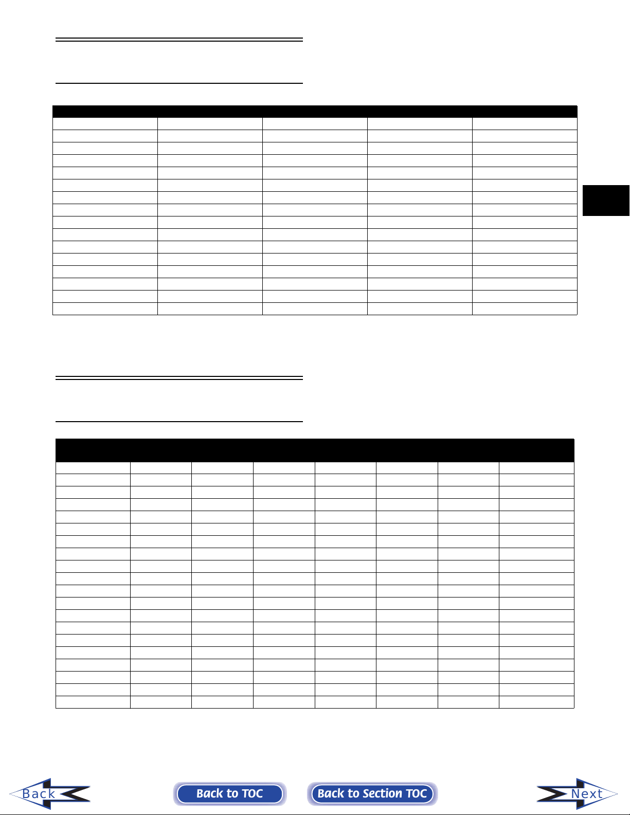
Torque Conversions
ft-lb x 0.1383 = kg-m
ft-lb kg-m ft-lb kg-m ft-lb kg-m ft-lb kg-m ft-lb kg-m
1 0.1 21 2.9 41 5.7 61 8.4 81 11.2
2 0.3 22 3.0 42 5.8 62 8.6 82 11.3
3 0.4 23 3.2 43 5.8 63 8.7 83 11.5
4 0.6 24 3.3 44 6.1 64 8.9 84 11.6
5 0.7 25 3.5 45 6.2 65 9.0 85 11.8
6 0.8 26 3.6 46 6.4 66 9.1 86 11.9
7 1.0 27 3.7 47 6.5 67 9.3 87 12.0
8 1.1 28 3.9 48 6.6 68 9.4 88 12.2
9 1.2 29 4.0 49 6.8 69 9.5 89 12.3
10 1.4 30 4.2 50 6.9 70 9.7 90 12.5
11 1.5 31 4.3 51 7.1 71 9.8 91 12.6
12 1.7 32 4.4 52 7.2 72 10.0 92 12.8
13 1.8 33 4.6 53 7.3 73 10.1 93 12.9
14 1.9 34 4.7 54 7.5 74 10.2 94 13.0
15 2.1 35 4.8 55 7.6 75 10.4 95 13.1
16 2.2 36 5.0 56 7.7 76 10.5 96 13.3
17 2.4 37 5.1 57 7.9 77 10.7 97 13.4
18 2.5 38 5.3 58 8.0 78 10.8 98 13.6
19 2.6 39 5.4 59 8.2 79 10.9 99 13.7
20 2.8 40 5.5 60 8.3 80 11.1 100 13.8
kg-m x 7.235 = ft-lb
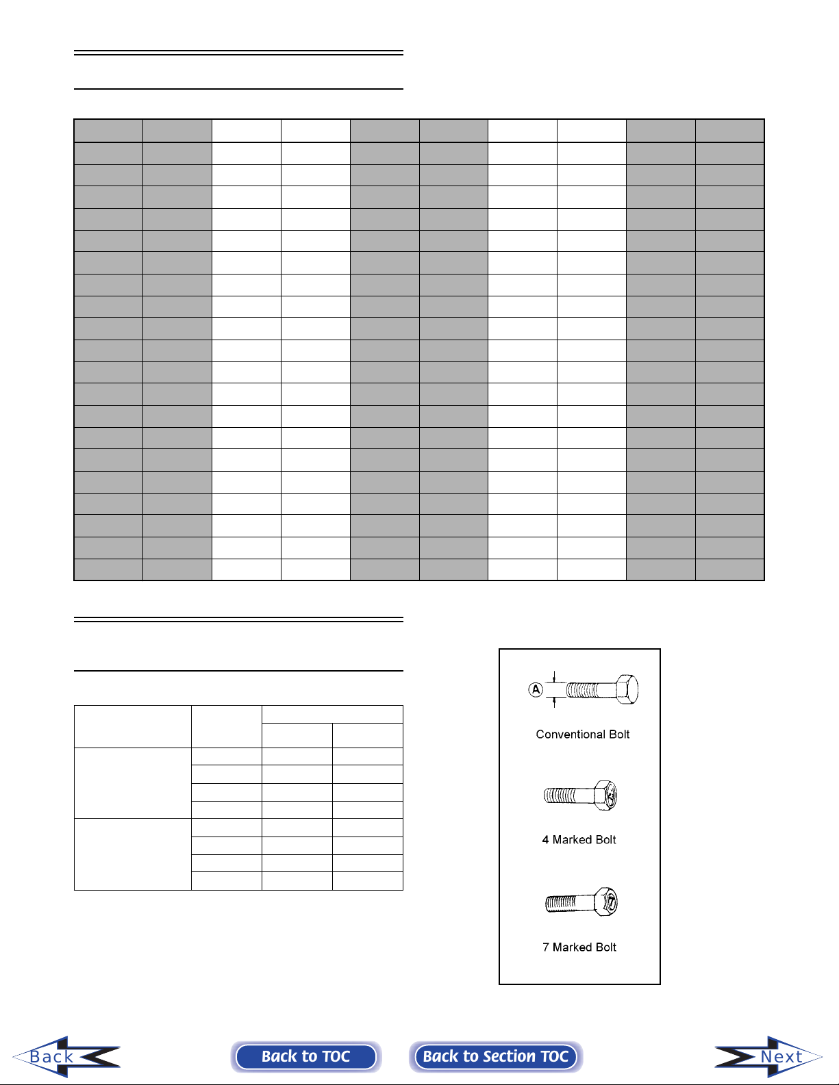
Tightening Torque
(General Bolts)
Type of Bolt
(Conventional or
4 Marked Bolt)
(7 Marked Bolt)
Thread
Diameter
A (mm)
5 0.2-0.4 1.5-3.0
6 0.4-0.7 3.0-5.0
8 1.0-1.6 7.0-11.5
10 2.2-3.5 16.0-25.5
5 0.3-0.6 2.0-4.5
6 0.8-1.2 6.0-8.5
8 1.8-2.8 13.0-20.0
10 4.0-6.0 29.0-43.5
Tightening Torque
kg-m ft-lb
Back
1-8
Back to TOC
Back to Section TOC
Next
Fraction/Decimal
Conversion Chart
8ths 16ths 32nds 64ths 64ths (cont)
1/8 = .125 1/16 = .0625 1/32 = .03125 1/64 = .015625 33/64 = .515625
1/4 = .250 3/16 = .1875 3/32 = .09375 3/64 = .046875 35/64 = .546875
3/8 = .375 5/16 = .3125 5/32 = .15625 5/64 = .078125 37/64 = .578125
1/2 = .500 7/16 = .4375 7/32 = .21875 7/64 = .109375 39/64 = .609375
5/8 = .625 9/16 = .5625 9/32 = .28125 9/64 = .140625 41/64 = .640625
3/4 = .750 11/16 = .6875 11/32 = .34375 11/64 = .171875 43/64 = .671875
7/8 = .875 13/16 = .8125 13/32 = .40625 13/64 = .203125 45/64 = .703125
— 15/16 = .9375 15/32 = .46875 15/64 = .234370 47/64 = .734375
— — 17/32 = .53125 17/64 = .265625 49/64 = .765625
— — 19/32 = .59375 19/64 = .296875 51/64 = .796875
— — 21/32 = .65625 21/64 = .328125 53/64 = .828125
— — 23/32 = .71875 23/64 = .359375 55/64 = .859375
— — 25/32 = .78125 25/64 = .390625 57/64 = .890625
— — 27/32 = .84375 27/64 = .421875 59/64 = .921875
— — 29/32 = .90625 29/64 = .453125 61/64 = .953125
— — 31/32 = .96875 31/64 = .484375 63/64 = .984375
1
Drill Bit Sizes
(Number)
No. Size of Drill in
Inches
1 .2280 21 .1590 41 .0960 61 .0390
2 .2210 22 .1570 42 .0935 62 .0380
3 .2130 23 .1540 43 .0890 63 .0370
4 .2090 24 .1520 44 .0860 64 .0360
5 .2055 25 .1495 45 .0820 65 .0350
6 .2040 26 .1470 46 .0810 66 .0330
7 .2010 27 .1440 47 .0785 67 .0320
8 .1990 28 .1405 48 .0760 68 .0310
9 .1960 29 .1360 49 .0730 69 .0292
10 .1935 30 .1285 50 .0700 70 .0280
11 .1910 31 .1200 51 .0670 71 .0260
12 .1890 32 .1160 52 .0635 72 .0250
13 .1850 33 .1130 53 .0595 73 .0240
14 .1820 34 .1110 54 .0550 74 .0225
15 .1800 35 .1100 55 .0520 75 .0210
16 .1770 36 .1065 56 .0465 76 .0200
17 .1730 37 .1040 57 .0430 77 .0180
18 .1695 38 .1015 58 .0420 78 .0160
19 .1660 39 .0995 59 .0410 79 .0145
20 .1610 40 .0980 60 .0400 80 .0135
Chart
No. Size of Drill in
Inches
No. Size of Drill in
Inches
No. Size of Drill in
Inches
Back
Back to TOC
Back to Section TOC
1-9
Next

MM/IN. Conversion
Chart
mm in. mm in. mm in. mm in. mm in.
.01 .00039 .41 .01614 .81 .03189 21 .82677 61 2.40157
.02 .00079 .42 .01654 .82 .03228 22 .86614 62 2.44094
.03 .00118 .43 .01693 .83 .03268 23 .90551 63 2.48031
.04 .00157 .44 .01732 .84 .03307 24 .94488 64 2.51968
.05 .00197 .45 .01772 .85 .03346 25 .98425 65 2.55905
.06 .00236 .46 .01811 .86 .03386 26 1.02362 66 2.59842
.07 .00276 .47 .01850 .87 .03425 27 1.06299 67 2.63779
.08 .00315 .48 .01890 .88 .03465 28 1.10236 68 2.67716
.09 .00354 .49 .01929 .89 .03504 29 1.14173 69 2.71653
.10 .00394 .50 .01969 .90 .03543 30 1.18110 70 2.75590
.11 .00433 .51 .02008 .91 .03583 31 1.22047 71 2.79527
.12 .00472 .52 .02047 .92 .03622 32 1.25984 72 2.83464
.13 .00512 .53 .02087 .93 .03661 33 1.29921 73 2.87401
.14 .00551 .54 .02126 .94 .03701 34 1.33858 74 2.91338
.15 .00591 .55 .02165 .95 .03740 35 1.37795 75 2.95275
.16 .00630 .56 .02205 .96 .03780 36 1.41732 76 2.99212
.17 .00669 .57 .02244 .97 .03819 37 1.45669 77 3.03149
.18 .00709 .58 .02283 .98 .03858 38 1.49606 78 3.07086
.19 .00748 .59 .02323 .99 .03898 39 1.53543 79 3.11023
.20 .00787 .60 .02362 1.0 .03937 40 1.57480 80 3.14960
.21 .00827 .61 .02402 1 .03937 41 1.61417 81 3.18897
.22 .00866 .62 .02441 2 .07874 42 1.65354 82 3.22834
.23 .00906 .63 .02480 3 .11811 43 1.69291 83 3.26771
.24 .00945 .64 .02520 4 .15748 44 1.73228 84 3.30708
.25 .00984 .65 .02559 5 .19685 45 1.77165 85 3.34645
.26 .01024 .66 .02598 6 .23622 46 1.81102 86 3.38582
.27 .01063 .67 .02638 7 .27559 47 1.85039 87 3.42519
.28 .01102 .68 .02677 8 .31496 48 1.88976 88 3.46456
.29 .01142 .69 .02717 9 .35433 49 1.92913 89 3.50393
.30 .01181 .70 .02756 10 .39370 50 1.96850 90 3.54330
.31 .01220 .71 .02795 11 .43307 51 2.00787 91 3.58267
.32 .01260 .72 .02835 12 .47244 52 2.04724 92 3.62204
.33 .01299 .73 .02874 13 .51181 53 2.08661 93 3.66141
.34 .01339 .74 .02913 14 .55118 54 2.12598 94 3.70078
.35 .01378 .75 .02953 15 .59055 55 2.16535 95 3.74015
.36 .01417 .76 .02992 16 .62992 56 2.20472 96 3.77952
.37 .01457 .77 .03032 17 .66929 57 2.24409 97 3.81889
.38 .01496 .78 .03071 18 .70866 58 2.28346 98 3.85826
.39 .01535 .79 .03110 19 .74803 59 2.32283 99 3.89763
.40 .01575 .80 .03150 20 .78740 60 2.36220 100 3.93700
Back
1-10
Back to TOC
Back to Section TOC
Next
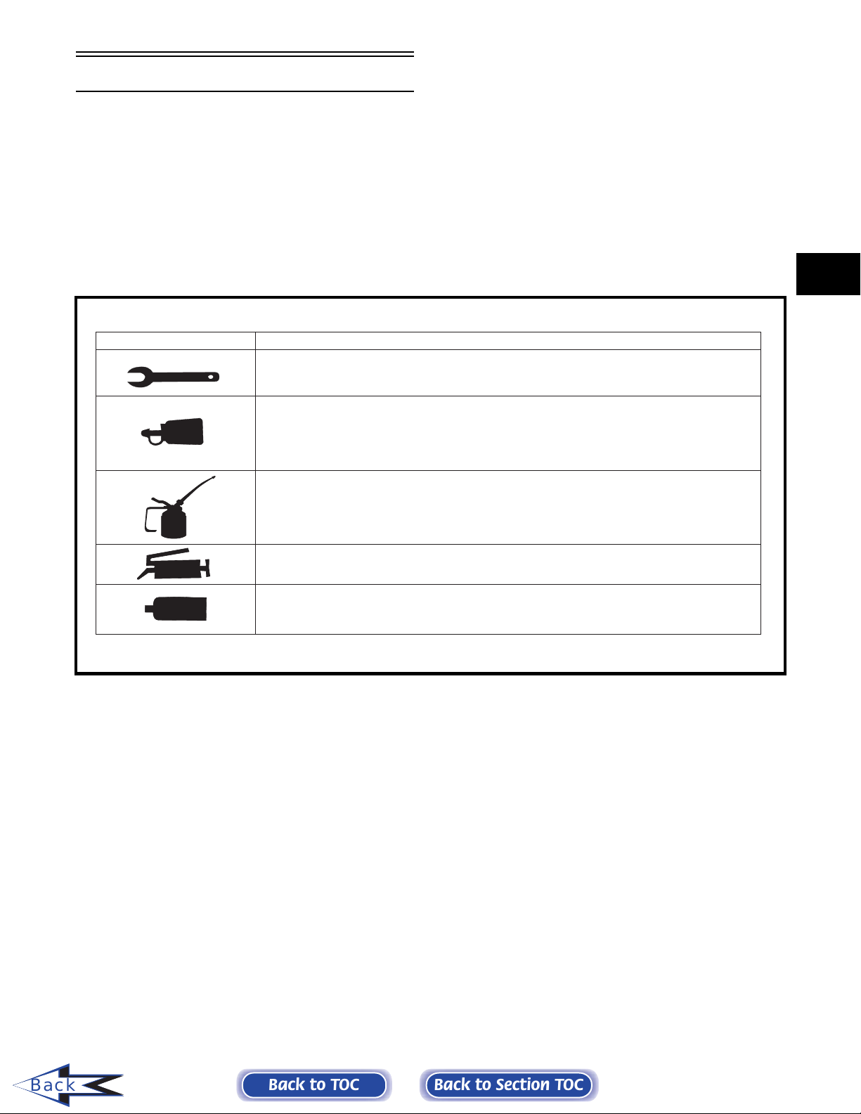
Servicing Symbols
Listed in the table below are symbols indicating special
instructions and other important information necessary
for proper servicing. Please note the definition for each
symbol. These symbols are used throughout this two-volume set.
1
SYMBOL
DESCRIPTION
Torque control required
242 - apply blue Loctite #242 (p/n 1639-815)
243 - apply blue Loctite #243 (p/n 1639-413)
270 - apply green Loctite #270 (p/n 1639-817)
271 - apply red Loctite #271 (p/n 1639-820)
609 - apply green Loctite #609 (p/n 1639-821)
Lubricate with Arctic Cat 50:1 Injection Oil (p/n 0636-286)
Lubricate with Arctic Cat Extreme 50:1 Injection Oil (p/n 0639-112)
Lubricate with Arctic Cat Low-Temp Grease (p/n 0636-593)
3B - Three Bond Sealant (p/n 0636-070)
HT - High-Temp Sealant (p/n 0636-069)
AS - Anti-Seize Thread Compound (p/n 0678-146)
Back
Back to TOC
Back to Section TOC
1-11

SECTION 2 — ENGINE
2
Engine ..................................................................... 2-2
Removing Engine (Table of Contents)..................... 2-2
Disassembling Engine (Table of Contents) ........... 2-12
Servicing Components (120 cc) ............................ 2-48
Cleaning and Inspecting Engine ........................... 2-58
Measuring Critical Components ............................ 2-62
2002 Arctic Cat Engine Specifications .................. 2-66
Assembling Engine (Table of Contents) ................ 2-67
Assembly Schematics (Table of Contents) .......... 2-114
Installing Engine (Table of Contents)................... 2-130
Troubleshooting Engine (120 cc)......................... 2-139
Troubleshooting Engine (Carbureted Models) ..... 2-140
Troubleshooting Engine (EFI Models) ................. 2-144
Engine Information (Table of Contents)............... 2-148
Back to TOC
TABLE OF
CONTENTS
2-1

Engine
This engine servicing section has been organized into
sub-sections which show a progression for the complete servicing of the Arctic Cat engine. For consistency purposes, this section shows a complete and
thorough progression; however, for efficiency it may
be preferable to remove the engine as a complete
assembly, to remove and disassemble only those components which need to be addressed, and to service
only those components. Also, some components may
vary from model to model. The technician should use
discretion and sound judgment.
NOTE: Some illustrations and photographs used
in this section are used for clarity purposes only
and are not designed to depict actual conditions.
2. Remove the two cap screws securing the steering
post to the steering post support. Account for two
bearing halves, two lock nuts, and a bearing
retainer.
A023A
3. Pull the steering post up and back and then out of
the lower steering post bearing.
Removing Engine
Table of Contents
120 cc Model........................................................... 2-2
Twin F/C Models...................................................... 2-3
500/600/800 cc Twin Models................................... 2-5
550 cc Models ......................................................... 2-7
Triple Models ........................................................... 2-9
Removing Engine
(120 cc Model)
NOTE: The drive chain must be removed in order
to remove the engine (see Drive Chain and Sprockets sub-section in Section 8).
1. Disconnect the choke and throttle cables from the
carburetor; then on each cable, loosen the
adjustment jam nut closest to the carburetor and
remove the cables from the bracket. Route the
cables out of the way.
4. Remove the two lock nuts securing the tie rods to
the steering post; then remove the tie rods from the
steering post. Place the steering post out of the
way on the right-hand side of the engine
compartment.
A024
5. Cut the cable tie; then disconnect all wires (a total
of four) at the front of the engine. Route them out
of the way.
2-2
Back to TOC
A046A
6. Turn the gas tank shut-off valve to the CLOSED
position.
Back to Section TOC
A047
Next

! WARNING
Whenever any maintenance or inspection is made
on a fuel system when there may be fuel leakage,
there should be no welding, smoking, open flames,
etc., in the area.
7. Disconnect the fuel hose from the carburetor.
NOTE: Be prepared to wipe up any fuel spillage.
8. Pull the recoil starter rope out approximately 60
cm (24 in.); then tie a slip-knot in the starter rope
below the console and allow the rope to slowly
retract against the starter case.
9. Remove the knot at the handle and remove the
handle; then thread the rope through the bushing in
the console.
10. At this point, scribe a line at the front of the engine
and measure the distance between the crankshaft
and the driveshaft. Record the measurement for
installing purposes.
NOTE: The front center plug is to access the oil
drain plug.
13. Place the snowmobile in the upright position; then
on the left-hand side of the engine, remove the
three cap screws securing the engine and brake
bracket to the front end.
A050A
14. Remove the engine from the engine compartment.
2
A048
11. Lay the snowmobile on its side.
NOTE: A piece of cardboard should be used to
protect the finish.
12. Using a flat-blade screwdriver, remove the four
belly pan plugs covering the engine mounting cap
screws; then remove the cap screws. Account for
eight washers and four lock nuts.
Removing Engine
(Twin F/C Models)
NOTE: If equipped with electric start, disconnect
the battery.
1. Turn the gas tank shut-off valve to the CLOSED
position.
2. Open the belt guard.
3. Remove the drive belt; then remove the plug from
the belly pan.
NOTE: Before installing the clutch puller, apply
oil to the threads of the puller and a small amount
of grease to the tip of the puller.
4. Remove the bolt and lock washers securing the
drive clutch to the crankshaft; then using the Drive
Clutch Puller (p/n 0644-207) and an impact
wrench or a breaker bar and Drive Clutch Spanner
Wrench (p/n 0644-136), tighten the puller. If the
drive clutch will not release, sharply strike the
head of the puller with a hammer. Repeat this
procedure until the clutch releases.
Back
Back to TOC
A049
Back to Section TOC
2-3
Next

AF472D
AF476D
5. Remove the clutch from the engine compartment.
AF473D
8. Remove the springs securing the expansion
chamber to the exhaust manifold and resonator;
then remove expansion chamber.
6. Remove the cap screw and washer securing the
driven pulley; then slide the pulley off the driven
shaft. Account for and note the position of any
alignment washers.
NOTE: If the driven pulley will not slide off the
driven shaft, use the Driven Pulley Puller (p/n
0744-023) for removal.
SC013D
7. Remove the torque bumper. Account for any
engine mount shims.
AC067
9. Remove the cap screws and lock washers securing
the recoil starter; then remove the starter. Leave it
in the engine compartment.
AB082
10. Disconnect the four-prong main wiring harness
connector and the CDI unit wiring harness.
11. Disconnect the impulse hose from the crankcase.
12. Disconnect the spark plug caps.
Back
2-4
Back to TOC
13. Loosen the carburetor flange clamp(s). Remove
the carburetor(s) from the intake flange(s) and
carburetor boot(s). Place the carburetor(s) to the
side in an upright position.
Back to Section TOC
Next

NOTE: If equipped with electric start, remove the
lock nuts and washers securing the starter motor
to the engine mounting bracket and remove the
starter motor.
Removing Engine
(500/600/800 cc Twin Models)
14. Disconnect the oil-injection cable from the oil-
injection pump. Account for the E-clip and
washer; then disconnect the oil supply hose from
the pump and plug the hose to prevent leakage.
AB081
NOTE: If equipped with electric start, remove the
two lock nuts and washers securing the starter
motor bracket; then remove the three remaining
cap screws, washers, and lock washers securing
the starter motor bracket and ground cable.
Remove the starter motor bracket.
15. Remove the cap screws securing the engine to the
front end. Account for washers, cap screws, and
lock nuts.
NOTE: Some engines are equipped with Arctic
Power Valves (APV). Closely observe the NOTE:
introducing this important information.
NOTE: If applicable, disconnect the battery
cables.
1. Turn the gas tank shut-off valve to the CLOSED
position.
2. Remove all springs securing the expansion
chamber(s) and remove the expansion chamber(s)
from the engine compartment.
3. Open the belt guard; then remove the drive belt.
4. Remove the plug from the belly pan. Using a ½-in.
12-point socket, remove the cap screw and lock
washer securing the drive clutch to the crankshaft;
then using Clutch Puller (p/n 0644-207) and an
impact wrench or a breaker bar and Spanner
Wrench (p/n 0644-136), tighten the puller. If the
drive clutch will not release, sharply strike the
head of the puller. Repeat this step until the clutch
releases. Remove the drive clutch. If applicable,
account for the two sleeves.
2
Back
AL201D
16. Lift the engine out of the engine compartment.
17. Remove the cap screws, washers, and lock
washers securing the engine mounting brackets to
the engine; then remove the brackets.
Back to TOC
5. Remove the cap screw and washer securing the
driven pulley; then slide the driven pulley off the
driven shaft. Account for a key, stub shaft, and
alignment washers.
Back to Section TOC
AN380D
AF120D
2-5
Next

NOTE: If the driven pulley is tight on the driven
shaft, pull the driven pulley off using the Driven
Pulley Puller (p/n 0744-023).
NOTE: Steps 6 through 12 are for APV equipped
engines.
6. Remove the two cap screws securing the
servomotor cover.
AP116A
7. Using a small screwdriver, pry off the cable
retaining cover.
AP118B
10. Remove the screw securing the servomotor
mounting plate to the air-intake silencer; then pull
the mounting plate forward and up to remove it
from the silencer. Lay the mounting plate aside out
of the way.
AP117A
8. Rotate the servomotor actuator counterclockwise
to loosen the cable; then pull the cable housings
out of the holder.
AP118A
AP127
11. Lift the silencer cover and remove the CDI unit;
then lay the unit aside out of the way.
12. Remove the two APV drain hoses and route them
out of the way.
AP128A
13. If applicable, remove the machine screw and
washer securing the mounting plate (for the
ignition coil and fuel pump) to the air-intake
silencer.
Back
9. Pull the cable up and out of the cable housing
holder; then slide each cable drum to the left and
out of the servomotor actuator.
2-6
Back to TOC
14. Remove the screws securing the air-intake
silencer; then move the silencer forward and out of
the engine compartment.
Back to Section TOC
Next

15. Disconnect the oil-injection cable/control rod from
the oil-injection pump; then disconnect the oilsupply hose from the pump and plug the hose to
prevent oil drainage.
16. Loosen the flange clamps securing the throttle
body/carburetor to the flange; then remove the
throttle body/carburetor. Place them to one side in
an upright position.
17. On carbureted models, disconnect the impulse
hose from the crankcase.
AP126
24. Loosen the clamp securing the supply hose to the
coolant tank and remove the hose. Loosen the
clamp securing the hose to the thermostat cap;
then remove the hose from the cap.
AN385D
18. Loosen the engine torque bumper and remove the
left rear engine nut and washer.
AN610D
19. Secure the hood with a tie-down strap; then
remove the hood cable.
20. Disconnect all electrical wires from the engine.
21. Remove the recoil starter from the engine. Leave it
in the engine compartment.
NOTE: If applicable, disconnect the solenoid-to-
starter motor cable from the starter motor.
22. Loosen the cap screws/lock nuts securing the
engine mounting brackets to the front end.
23. Remove the cap from the coolant drain hose and
route the hose into a suitable container. Remove
the filler cap; then once the coolant stops draining,
install the drain hose cap.
NOTE: Inspect the engine to ensure all wires,
hoses, and cables have been removed.
25. Lift the engine with mounting brackets out of the
engine compartment.
26. Remove the cap screws securing the engine
mounting brackets to the crankcase; then remove
the brackets.
27. Remove the exhaust manifold from the engine.
Account for nuts, washers, and gaskets.
28. Remove the clamp securing the coolant supply
hose to the water pump. Then remove the hose
from the pump.
Removing Engine
(550 cc Models)
1. Disconnect the battery cables making sure to
disconnect the negative cable first.
2. Turn the gas tank shut-off valve to the CLOSED
position.
3. Remove the cable tie and positive battery cable
from the starter motor.
4. On the Wide Track, remove the two lock nuts
securing the starter motor to the engine mounting
bracket; then place the starter motor and end cap
off to the side.
5. Remove the springs securing the expansion
chamber to the exhaust manifold, front end, and
resonator. Remove the expansion chamber and
grafoil gasket.
2
Back
Back to TOC
Back to Section TOC
2-7
Next

6. Attach a long piece of fuel hose to the engine
coolant drain (located on the exhaust side of the
engine). Route the hose outside the engine
compartment and into a container. Open the drain
and remove the filler cap. Once the coolant stops
flowing, remove the hose and tighten the drain
valve.
AP058
7. Open the belt guard: then remove the drive belt.
NOTE: On the Wide Track, remove the machine
screws securing the side panel to the belly pan;
then remove the side panel. On the Pantera 550
and ZL 550, remove the rubber plug from the belly
pan.
AF459D
9. Remove the cap screw and washer securing the
driven pulley; then slide the driven pulley off the
driven shaft. Account for a key and alignment
washers.
AM115D
8. Using a ½-in. twelve-point socket, remove the bolt
and lock washer securing the drive clutch to the
crankshaft. Using the Clutch Puller (p/n 0644-207)
and an impact wrench or a breaker bar and the
Flywheel Pulley/Spanner Wrench (p/n 0144-310),
tighten the puller. If the drive clutch will not
release, sharply strike the head of the puller.
Repeat this step until the clutch releases. Remove
the drive clutch. If applicable, account for the two
sleeves.
NOTE: On the Wide Track, remove the lock nut
securing the belly pan and bumper to the bumper
support tube; then remove the rear plug from the
belly pan.
AF120D
NOTE: If the driven pulley is tight on the driven
shaft, pull the driven pulley off using the Driven
Pulley Puller (p/n 0744-023).
10. Loosen the flange clamp securing each carburetor
to its flange; then remove the carburetors. Position
the carburetors to one side in an upright position.
AJ172
11. Disconnect the impulse hose from the crankcase.
12. Remove the cable tie securing the engine and CDI
wiring harnesses to the engine; then disconnect the
main wiring harness from the engine and CDI
wiring harnesses.
Back
2-8
Back to TOC
Back to Section TOC
Next

13. Remove the spark plug caps and the cable tie
securing the temperature-gauge sender wire; then
disconnect the sender wire.
14. On the Wide Track, remove the ground wire from
the magneto housing.
15. Remove the E-clip and washer securing the oilinjection cable; then disconnect the oil-injection
cable from the pump. Disconnect the oil-supply
hose from the pump and plug the hose to prevent
oil drainage.
AN009
AN013
20. Lift the engine with mounting brackets out of the
engine compartment.
! CAUTION
Do not use the starter motor shaft to lift the
engine. Damage may occur.
21. Remove the engine mounting brackets.
2
16. Loosen the clamp securing the supply hose to the
water pump housing; then remove the hose from
the water pump. Loosen the clamp securing the
hose to the thermostat cap; then remove the hose
from the cap.
17. Remove the four cap screws and lock washers
securing the recoil starter; then remove the starter
from the engine. Leave it in the engine
compartment.
NOTE: On the Pantera 550, account for the
ground wire.
18. Support the hood; then remove the hood cable
from the exhaust manifold.
19. Remove the mounting hardware securing the
engine to the front end.
NOTE: On the Wide Track, account for shims and
note their position on the left rear engine mount
for assembly purposes.
Removing Engine
(Triple Models)
NOTE: Some engines are equipped with Arctic
Power Valves (APV). Closely observe the NOTE:
introducing this important information.
1. Turn the gas tank shut-off valve to the CLOSED
position.
AL658D
2. Secure the hood with a hold-down strap; then
remove the hood cable.
Back
Back to TOC
AR321
3. Remove the springs securing the expansion
chambers to the header pipes, the front end, and
the resonator. Remove the expansion chambers
and three grafoil gaskets.
NOTE: Number the expansion chambers before
removing to aid in assembly.
Back to Section TOC
2-9
Next

4. Remove the cap screws securing the resonator.
Account for and note the location of the engine
ground cable with star washer, washers, bushings,
spacers, and retaining nuts.
5. Attach a long piece of fuel hose to the engine
coolant drain. Route the hose outside the engine
compartment and into a container. Open the drain
valve; then remove the coolant filler cap to vent
the system. Once the coolant stops flowing,
remove the hose and tighten the drain valve.
AQ123
NOTE: Steps 9 through 15 are for APV equipped
engines.
9. Remove the two cap screws securing the
servomotor cover.
AP116A
10. Using a small screwdriver, pry off the cable
retaining cover.
6. Open the belt guard; then remove the drive belt.
7. Remove the plug from the belly pan; then using a
1/2 in. twelve-point socket, remove the bolt and
lock washer securing the drive clutch to the
crankshaft. Using the Drive Clutch Puller (p/n
0644-207) and an impact wrench or a breaker bar
and Spanner Wrench (p/n 0644-136), tighten the
puller. If the drive clutch will not release, sharply
strike the head of the puller. Repeat this step until
the clutch releases. Remove the drive clutch. If
applicable, account for the two sleeves.
AF472D
AP117A
11. Rotate the servomotor actuator counterclockwise
to loosen the cable; then pull the cable housings
out of the holder.
Back
8. Remove the cap screw securing the driven pulley;
then slide the driven pulley off the driven shaft.
Account for a stub shaft, the location of all
washers, and a key.
NOTE: If the driven pulley is tight on the shaft,
pull the driven pulley off using the Driven Pulley
Puller (p/n 0744-023).
2-10
Back to TOC
AP118A
12. Pull the cable up and out of the cable housing
holder; then slide each cable drum to the left and
out of the servomotor actuator.
Back to Section TOC
Next

AP118B
AN614D
13. Remove the screw securing the servomotor
mounting plate to the air-intake silencer; then pull
the mounting plate forward and up to remove it
from the silencer. Lay the mounting plate aside out
of the way.
AP127
14. Lift the silencer cover and remove the CDI unit;
then lay the unit aside out of the way.
15. Remove the two APV drain hoses and route them
out of the way.
17. Disconnect the impulse hose from the crankcase.
18. Loosen the engine torque bumper; then remove the
left-side rear engine nut and washer.
2
AN610D
19. Disconnect the engine and timing sensor wiring
harnesses from the main wiring harness. Remove
the spark-plug caps from the spark plugs. Remove
the cap screw securing the two ground wires to the
magneto housing cover.
20. Remove the E-clip and washer securing the oilinjection cable; then disconnect the oil-injection
cable from the oil-injection pump. Disconnect the
oil-supply hose and the oil-output hose from the
pump and plug the hoses to prevent oil drainage.
Back
AP128A
16. Label the carburetors. Loosen the flange clamp
securing each carburetor to its flange; then remove
the carburetors from the intake flanges. Position
the carburetors to one side in an upright position.
Back to TOC
Back to Section TOC
AN392D
2-11
Next

21. Loosen the clamp securing the coolant supply hose
to the water pump housing; then remove the hose
from the water pump. Loosen the clamp securing
the hose to the thermostat cap; then remove the
hose from the cap.
Disassembling Engine
Table of Contents
22. Disconnect the temperature-gauge sender wire.
AJ663
23. Remove the cap screws securing the engine
mounting brackets to the front end. Account for
mounting hardware.
24. Lift the MAG-side of the engine. Remove the four
cap screws and lock washers securing the recoil
starter; then remove the starter from the engine.
Leave it in the engine compartment.
NOTE: If applicable, disconnect the solenoid- to-
starter motor cable from the starter motor.
120 cc Model......................................................... 2-12
370/440 cc Models ................................................ 2-17
550 cc Models ....................................................... 2-20
570 cc Models ....................................................... 2-23
500/600 cc Twin Models........................................ 2-29
800 cc Models ....................................................... 2-34
600 cc Triple Model ............................................... 2-39
1000 cc Models ..................................................... 2-45
Disassembling Engine
(120 cc Model)
1. Remove the oil drain plug and drain the oil; then
install the oil plug and tighten securely.
AN012
25. Lift the engine with engine mounting brackets out
of the engine compartment.
26. Remove the mounting brackets from the
crankcase.
GM300D
2. Remove the wing nut securing the air cleaner end
cap to the air cleaner housing.
3. Remove the cap screw and flange nuts securing
the air cleaner housing to the carburetor and
engine.
A002
Back
2-12
Back to TOC
Back to Section TOC
Next

GF314D
GF208D
4. Remove the air breather hose from the air cleaner
housing; then remove the air cleaner housing from
the carburetor. Account for the gasket.
A001
6. Slide the carburetor off the mounting studs.
Account for a gasket, insulator block, and a
gasket.
2
GF318D
7. Remove the recoil starter/fan housing assembly.
Back
GF316D
5. Mark the locations of the springs for assembly;
then disconnect the rod and spring from the
carburetor.
Back to TOC
8. Remove the screws securing the recoil starter
pulley to the flywheel; then remove the nut
securing the flywheel to the crankshaft.
Back to Section TOC
GM201D
2-13
Next

GM202D
GM203D
GE318D
12. Remove the cylinder head cover.
9. Using a flywheel puller, remove the flywheel.
GM110D
10. Remove the high tension lead from the spark plug
and two wire forms; then disconnect the ignition
coil wire.
11. Remove the cap screws securing the ignition coil
to the crankcase housing.
GM205D
13. Remove the air breather body assembly from the
cylinder head cover. Account for a gasket.
GM206D
14. Remove the screws securing the reed stopper to
the air breather body assembly.
Back
2-14
Back to TOC
Back to Section TOC
Next

GM207D
15. Remove the lock nuts and pivots securing the
rocker arms to the cylinder head.
GM208D
16. Remove the push rods.
GM210D
2
GM211D
18. Remove the cap screws securing the crankcase
side cover to the crankcase. Account for dowel
pins and a gasket.
Back
GM209D
17. Remove the cap screws securing the head to the
cylinder; then remove the head and account for a
gasket. Note the location of the dowel pins.
Back to TOC
Back to Section TOC
GM212D
GM213D
2-15
Next

19. Remove the washer from camshaft and note the
location of the timing marks on the crankshaft and
camshaft gears.
21. Rotate the crankshaft until the piston is at the top
of the stroke; then using a chisel, loosen the
connecting rod nut locking tabs.
GM214D
GM215D
20. Remove the camshaft; then remove the tappets.
GM119D
22. Note the direction of the arrow on the connecting
rod and mark the connecting rod and end cap for
reference during installation.
GM121D
Back
2-16
Back to TOC
GM216D
GM217D
GM120D
23. Remove the connecting rod end cap and account
for the splasher plate and lock tab.
Back to Section TOC
Next

GM123D
24. Using two flat blade screwdrivers between the
connecting rod studs and the crankshaft web, push
upward on the piston.
GM122D
25. Remove the crankshaft.
GM126D
Disassembling Engine
(370/440 cc Models)
1. Remove the four nuts and lock washers securing
the exhaust manifold; then remove the exhaust
manifold. Account for two gaskets.
2. Noting the location of the longer cap screws for
assembly purposes, remove the 14 cap screws,
lock washers, and washers securing the top and
exhaust-side cooling shrouds.
3. Lift the top cooling shroud off the engine and slide
the exhaust-side cooling shroud off the exhaustmanifold studs. Account for two exhaust-manifold
shroud gaskets.
2
Back
GM124D
26. Remove the cap screws securing the oil level
sensor plate to the crankcase; then remove the
plate.
Back to TOC
4. Disconnect the two oil-injection hoses from their
fittings on the intake manifold (single carburetor)
or on the adapter plates (twin carburetor).
5. A. On the 370 cc, remove the nuts securing the
intake manifold; then remove the manifold with
flange from the engine. Account for two
insulators. Discard the gaskets.
B. On the 440 cc, remove the nuts, lock washers,
and washers securing the intake flanges; then
remove the flanges from the engine. Remove
the screws securing the adapter plates; then
remove the adapter plates. Discard the gaskets.
Back to Section TOC
AB014
2-17
Next

6. Remove the intake-manifold cooling shroud from
the engine. Discard the two gaskets.
7. Using Flywheel Spanner Wrench (p/n 0144-007)
to secure the crankshaft, remove the three cap
screws and lock washers securing the starter
pulley to the flywheel. Remove the starter pulley;
then carefully pry the fan belt drive pulley from its
seated position on the flywheel and remove.
AB020
8. Temporarily install the starter pulley on the
flywheel with three cap screws. Using the
flywheel spanner wrench to secure the crankshaft,
loosen and remove the flywheel nut and washers.
AB015
11. Install a protective cap onto the end of the
crankshaft.
NOTE: A suitable protective cap can be made by
welding a 3 mm (1/8 in.) plate on one side of a
spare flywheel nut.
AB021
NOTE: If an impact wrench is being used, use of
a flywheel spanner wrench will not be necessary.
9. Remove the cap screws securing the starter pulley
to the flywheel and remove the pulley.
10. Remove the flange nuts securing the fan case to
the crankcase; then remove the fan case.
NOTE: For further servicing of the axial fan com-
ponents, see section 3.
AB022
! CAUTION
To prevent damage to the crankshaft, thread a
protective cap onto the crankshaft. The puller
must bottom on the cap and not on the
crankshaft. Also, do not thread puller bolts more
than 12.7 mm (1/2 in.) into the flywheel. Damage
to the coils may result.
12. Using the Flywheel Puller/Spanner Wrench (p/n
0144-310) or suitable equivalent, remove the
flywheel from the crankshaft by tightening the
puller bolt, striking the head of the puller bolt with
a hammer, and tightening again. Repeat procedure
until the flywheel is free. Account for the key in
the end of the crankshaft.
Back
2-18
Back to TOC
Back to Section TOC
Next
 Loading...