

Page 1

W-E-B Telemetry
(Wireless Embedded
Baseboard for Telemetry)
Technical Manual
a
company
Page 2

A
Definitions
Arcom is the trading name for Arcom Control Systems Inc and Arcom Control Systems Ltd.
Disclaimer
The information in this manual has been carefully checked and is believed to be accurate. Arcom assumes no responsibility
for any infringements of patents or other rights of third parties, which may result from its use.
Arcom assumes no responsibility for any inaccuracies that may be contained in this document. Arcom makes no commitment
to update or keep current the information contained in this manual.
Arcom reserves the right to make improvements to this document and /or product at any time and without notice.
Warranty
This product is supplied with a 3 year limited warranty. The product warranty covers failure of any Arcom manufactured
product caused by manufacturing defects. The warranty on all third party manufactured products utilized by Arcom is limited
to 1 year. Arcom will make all reasonable effort to repair the product or replace it with an identical variant. Arcom reserves the
right to replace the returned product with an alternative variant or an equivalent fit, form and functional product. Delivery
charges will apply to all returned products. Please check www.arcom.com/support
Forms.
for information about Product Return
Trademarks
Windows NT, Windows 98 are trademarks of the Microsoft Corporation.
Linux is a registered trademark of Linus Torvalds.
All other trademarks recognized.
Revision History
Manual PCB Date Comments
th
Issue A V1 Issue 3 15
December 2005 First full release of Manual
© 2005 Arcom.
Arcom is a subsidiary of Spectris plc.
For contact details, see page 34
.
rcom operates a company-wide
quality management system
which has been certified by the
Page 3

W-E-B Telemetry Technical Manual Contents
Contents
About this manual ..............................................................................................................................5
Conventions...........................................................................................................................5
Related documents................................................................................................................5
Introduction ........................................................................................................................................6
Features.................................................................................................................................6
W-E-B Telemetry ‘at a glance’................................................................................................7
Handling your board safely ....................................................................................................8
Detailed hardware description ...........................................................................................................9
W-E-B Telemetry board footprint..........................................................................................10
Power supply requirements .................................................................................................10
Power conditioning...............................................................................................................10
Switch mode power supplies ...............................................................................................10
Network interface.................................................................................................................10
Serial interface.....................................................................................................................10
PC/104 bus support .............................................................................................................10
Power supervisory circuit ..................................................................................................... 11
Ignition sense circuit ............................................................................................................11
Dual UART 16C552 .............................................................................................................11
Modem ON / OFF control signal ..........................................................................................11
Status LEDs .........................................................................................................................12
Optional modules .............................................................................................................................13
Trimble GPS module............................................................................................................13
Sony Ericsson GPRS module ..............................................................................................13
Siemens GPRS module .......................................................................................................14
Motorola iDEN module.........................................................................................................15
Motorola WiDEN module .....................................................................................................16
Board configuration..........................................................................................................................17
Jumpers ...............................................................................................................................17
Equipment you will need ..................................................................................................................18
Supplied equipment .............................................................................................................18
What you will need...............................................................................................................18
Memory map ....................................................................................................................................19
Ports and connectors.......................................................................................................................20
J1 (Power connection) .........................................................................................................21
J2 (Ethernet LAN connection) and J4 (Ethernet from processor card) ...............................21
J3 (Siemens modem interface) ............................................................................................21
J5 (Lithium battery output) ...................................................................................................22
P5 (COM0 & COM1, RS-232)..............................................................................................23
J6 (COM0 & COM1 from processor card)............................................................................23
J7 (Sony Ericsson modem interface) ...................................................................................24
J8 (SIM card connector).......................................................................................................25
J9 (Ethernet LEDs) ..............................................................................................................25
J10 (iO200 modem antenna interface) ................................................................................25
© 2005 Arcom Issue A 3
Page 4

W-E-B Telemetry Technical Manual Contents
J11 (iO200 modem CELL antenna interface).......................................................................26
J12 (iO200 modem GPS antenna interface)........................................................................26
J17 (Auxiliary power) ...........................................................................................................26
J18 (iO200 modem Push To Talk - PTT)..............................................................................27
J19 (iO200 modem SIM card interface) ...............................................................................27
P2 (iO1500 modem interface)..............................................................................................27
P3 (GPS interface)...............................................................................................................28
P4 (PLD Program Header)...................................................................................................29
P60,61 PC/104 bus connectors)..........................................................................................29
P62 (iO200 modem interface)..............................................................................................30
Antenna considerations ...................................................................................................................32
Antenna safety.....................................................................................................................32
ESD protection.....................................................................................................................33
Antenna performance ..........................................................................................................33
Appendix A - Contacting Arcom .......................................................................................................34
Appendix B - Technical specifications..............................................................................................35
Appendix C - Mechanical specifications ..........................................................................................37
Index ................................................................................................................................................39
© 2005 Arcom Issue A 4
Page 5

W-E-B Telemetry Technical Manual About this manual
About this manual
This manual provides detailed information about the W-E-B Telemetry board.
It explains, with examples, how to get the most from this product.
Conventions
Symbols
The following symbols are used in this guide:
Symbol
Related documents
In addition to this manual, you can obtain useful information from a variety of sources
including:
Explanation
Note - information that requires your attention.
Tip - a handy hint that may provide a useful
alternative or save time.
Caution – proceeding with a course of action may
damage your equipment or result in loss of data.
Jumper fitted.
Jumper not fitted.
Motorola iO1500 iDEN Modem Module
•
Motorola iO200 WiDEN Modem Manual
•
Sony Ericsson GR47/48 Modem Manual
•
SIEMENS MC35i Modem Manual •
Trimble GPS Receiver Manual
•
SM-837/1900: RM3-900/1900 Antennas
•
Antennas
•
© 2005 Arcom Issue A 5
Page 6

W-E-B Telemetry Technical Manual Introduction
Introduction
The W-E-B Telemetry (Wireless Embedded Baseboard for Telemetry) board is a
rugged, modular platform for applications in telemetry and telematics. The board makes
it easy to integrate three essential features of any new asset monitoring solution wireless modem, GPS receiver and complete power supply solution to power your
system.
Features
Wide DC input voltage range (10V to 30V). •
•
Automotive transient and surge protected.
•
Supply reverse voltage protected.
•
Input power and ignition sensing circuitry.
•
8 / 16bit PC/104 bus interface.
•
On board 5V supply, delivers up to 2.5A (for host CPU and expansion modules).
•
On board 3.6V supply, delivers up to 2.5A (for breakout and wireless modules).
•
On board ±12V supply, delivers up to 250mA (for breakout and PC/104).
•
Extended temperature range lithium back-up battery for GPS module.
•
Dual 16C550 compatible UART provides serial link to wireless modules directly from
PC/104 bus.
•
EMC filtered breakout for two 16C550 serial ports.
•
Breakout for 10/100 Base-T Ethernet (with integrated activity and speed LEDs).
•
Direct Plug ‘n’ Go connection for Siemens MC35i OEM modem module.
•
Direct Plug ‘n’ Go connection for Sony Ericsson GR47/48 OEM modem module.
•
Direct Plug ‘n’ Go connection for Motorola iDEN iO1500 OEM modem module.
•
Direct Plug ‘n’ Go connection for Motorola WiDEN iO200 OEM modem module.
•
Direct Plug ‘n’ Go connection for Trimble Lassen SQ GPS module.
•
3 user definable status LEDs.
•
Integrated SIM (Subscriber Identity Module) card connector.
© 2005 Arcom Issue A 6
Page 7
W-E-B Telemetry Technical Manual Introduction
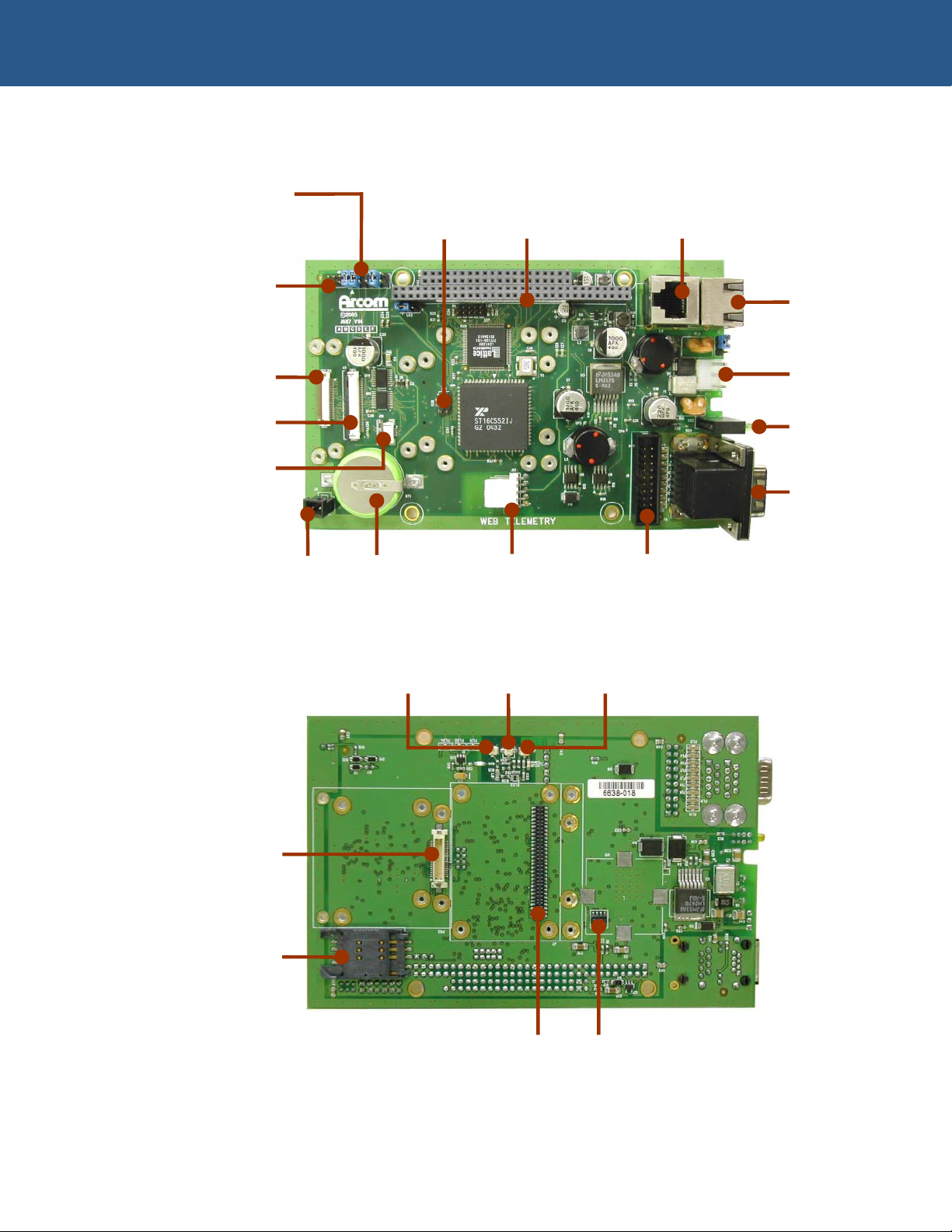
W-E-B Telemetry ‘at a glance’
Base Addr ess iO200 8/16bit Ethernet
selector link Push To PC1/104 pass through
Talk interface connector
Ethernet
LEDs
Ethernet
breakout
connector
iO1500
interface
MC35i
interface
iO200
SIM card
interface
3V lithium 3V lithium Auxiliary Serial ports
battery backup power pass through
connector battery connector
iO200 iO200 GPS iO200 CELL
antenna antenna antenna
DC input
connector
Power and
user LEDs
Dual stack
DB9
connector
(serial port
breakouts)
iO200
interface
SIM card
interface
GR47/47 GPS
interface interface
© 2005 Arcom Issue A 7
Page 8

W-E-B Telemetry Technical Manual Introduction
Handling your board safely
Anti-static handling
This board contains CMOS devices that could be damaged in the event of static
electricity discharged through them. At all times, please observe anti-static precautions
when handling the board. This includes storing the board in appropriate anti-static
packaging and wearing a wrist strap when handling the board.
Batteries
The W-E-B Telemetry board contains a Lithium battery to maintain the configuration of
the GPS unit, if present.
Do not short circuit the batteries or place on a metal surface where the battery
terminals could be shorted. During shipment the battery is isolated from the
boards circuitry and should be connected before using the board. Please refer
to the link section of this manual for details.
Dispose of used batteries according to the manufacturer’s instructions and
local ordinances. Do not incinerate, crush or otherwise damage the batteries.
The batteries are non-rechargeable. There is a danger of explosion if a lithium
battery is recharged or incorrectly replaced.
The Lithium battery on the W-E-B Telemetry base board has a life expectancy
of 5 years. This battery should only be replaced by qualified service
personnel.
Packaging
Please ensure that should a board need to be returned to Arcom, it is adequately
packed, preferably in the original packing material. If the original packing material is not
available, return the board in an anti-static bag contained within a box that provides
suitable protection.
Electromagnetic compatibility (EMC)
The W-E-B Telemetry board is classified as a component with regard to the European
Community EMC regulations, it is the responsibility of the end user to ensure that
systems using the board are compliant with the appropriate EMC standards.
Arcom EMC tests of the W-E-B Telemetry board have shown that the RF emissions of
the board are well below standard international EMC limits and that it is unlikely to
contribute significantly to the RF emissions spectrum of any system in which it is used.
The optional wireless modules catered for by the W-E-B Telemetry board all have full
regulatory approval from the appropriate agencies.
© 2005 Arcom Issue A 8
Page 9

W-E-B Telemetry Technical Manual Detailed hardware description
Detailed hardware description
The following section provides a detailed description of the functions offered by the
W-E-B Telemetry board. This information may be required during development.
3.6 VOLT
POWER IN
P
C
/
1
0
4
P
R
O
C
E
S
S
O
R
C
A
R
D
POWER
CONDITIONING
20
WAY
IDC
COM1
COM2
VERTICAL
SCREENED
RJ45
+5 VOLT
-12 VOLT
+12 VOLT
PC/104 BUS
CONNECTOR
3.6v DC / DC
CONVERTOR
5v DC / DC
CONVERTOR
DUAL
(STACK)
MALE 9
WAY
DTYPE
SCREENED
16C552
DUART
AND
74HC244
VOLTAGE
TRANSLATOR
LC4128
CPLD
5 VOLT
RIGHT
ANGLE
RJ45
USER
LEDS
+12 VOLT
+12v DC / DC
CONVERTOR
-12v DC / DC
CONVERTOR
-12 VOLT
WEB
TELEMETRY
M
O
U
N
T
I
N
G
H
O
L
E
S
SIM CARD
CONNECTOR
PCB
TRIMBLE
GPS
MODULE
SIEMENS
MODEM
MODULE
SONY
ERICSSON
MODEM
MODULE
MOTOROLA
MODEM
MODULE
W-E-B Telemetry block diagram
© 2005 Arcom Issue A 9
Page 10

W-E-B Telemetry Technical Manual Detailed hardware description
W-E-B Telemetry board footprint
The board is 100mm (3.93") by 155mm (6.10") and is 1.6mm (63 thou) thick.
Power supply requirements
The board is designed to accept a 10V to 30V DC power supply, nominally 12V DC.
Power conditioning
The input supply lines are protected using re-settable surface mount fuses. These fuses
can only be reset by power cycling the board.
The PCB also provides protection for reverse voltage and transient voltages to comply
with ETSI EN 301 489-1 V1.4.1, ISO 7637-1 and ISO 7637-2.
On board EMC filtering minimizes conducted noise.
Switch mode power supplies
On board DC/DC converters provide the necessary power rails:
+5V, 2.5A max. •
•
+3.6V, 2.5A max.
•
+12V, 250mA max.
•
-12V, 150mA max.
•
+1.8V, 100mA max (see Sony Ericsson modem module).
Network interface
A 10/100Base-T Ethernet connector is mounted on the front edge of the PCB to allow
direct mounting to a front panel. The RJ45 connector incorporates activity and speed
LEDs. The network connection is provided by the PC/104 processor card and is
connected to the board by a standard RJ45 cable.
Serial interface
A dual port male DB9 connector is mounted on the front edge of the PCB to allow direct
mounting to a front panel. The RS-232 serial connection is provided by the PC/104
processor card and is connected to the board by a standard 20-way IDC ribbon cable.
PC/104 bus support
The board includes an 8bit PC/104 slave interface conforming to IEEE996.1. The
module includes a 16bit connector to accommodate connections for additional interrupt
lines.
© 2005 Arcom Issue A 10
Page 11

W-E-B Telemetry Technical Manual Detailed hardware description
Power supervisory circuit
A supervisory circuit monitors the DC input supply. This signal creates an interrupt
(Power Fail) to indicate an occurrence of the DC supply voltage falling below 8V DC.
The number of interrupt resources required is minimized by concatenating several
interrupts into a single signal. This interrupt is concatenated with the Ignition Sense
interrupt.
Ignition sense circuit
A supervisory circuit monitors an auxiliary (Ignition) input supply. This signal creates an
interrupt (Ignition Sense) to indicate an occurrence of the DC supply voltage falling
below 8V DC and rising above 8V DC.
The number of interrupt resources required is minimized by concatenating several
interrupts into a single signal. This interrupt is concatenated with the Power Fail
interrupt.
Dual UART 16C552
Two on board 16C550 compatible serial ports support optional wireless modules, whilst
a parallel port supports digital I/O.
Modem ON / OFF control signal
When power is initially applied to the board, the modem modules are in a low power/off
state. Toggle the ON / OFF control signal to turn the modules on. The ON/OFF signal is
provided by the parallel port (bit 3). The address of this signal is Base address (as
selected at LK1) +10H.
To turn the modem module on, follow these steps:
1 Apply power to the board.
2 Write a ‘1’ to bit 3 of parallel port. The status of the signal is (on).
3 Wait 10ms then write a ‘0’ to bit 3 of parallel port. The status of the signal is
(off).
4 Wait 600ms, then write a ‘1’ to bit 3 of parallel port. The status of the signal is
(on).
To turn the Motorola modem module off, write a ‘0’ to bit 3 of parallel port, (off).
© 2005 Arcom Issue A 11
Page 12

W-E-B Telemetry Technical Manual Detailed hardware description
To turn the Sony Ericsson / Siemens modem module off, follow these steps:
1 Write a ‘1’ to bit 3 of parallel port. The status of the signal is (on).
2 Wait 10ms, then write a ‘0’ to bit 3 of parallel port. The status of the signal is
(off).
3 Wait 1000ms, then write a ‘1’ to bit 3 of parallel port. The status of the signal is
(on).
Status LEDs
Four status LEDs are provided, in a traffic light stacked arrangement. This is positioned
on the front edge of the PCB to allow direct mounting to a front panel:
A green LED provides visual confirmation of power. •
• A red LED and two yellow LEDS are user controlled.
The LEDs are accessed through the parallel port (bit 0 red; Bit 1 yellow; Bit 2 yellow).
The address of these LEDs is Base address (as selected at LK1) +10H.
Write a ‘1’ to the appropriate bit to turn the LED off.
Write a ‘0’ to the appropriate bit to turn the LED on.
© 2005 Arcom Issue A 12
Page 13
W-E-B Telemetry Technical Manual Optional modules
Optional modules
The optional modem modules are secured to the board via four 2mm * 12mm long
posidrive screws and four 4mm long spacers.
These parts are included with the PCB.
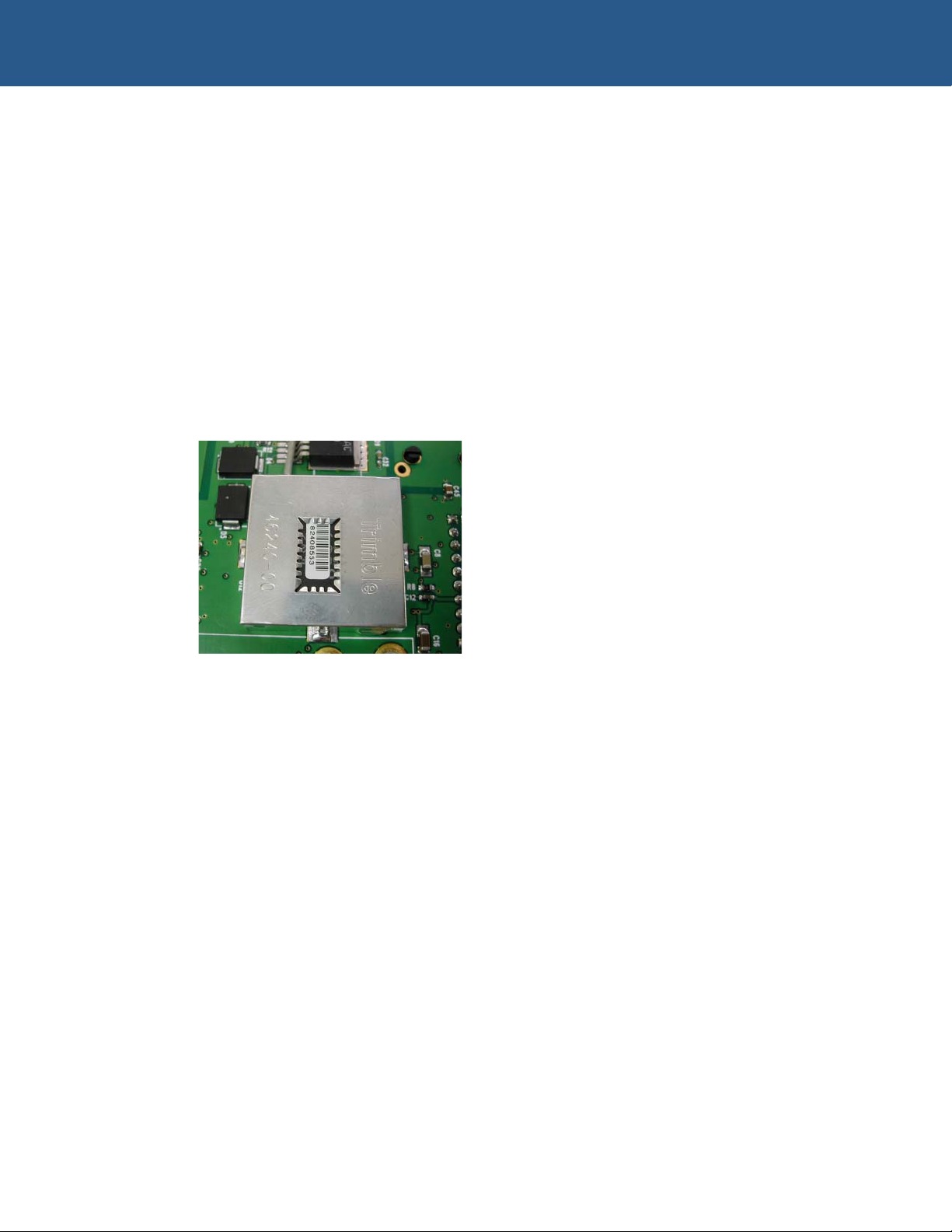
Trimble GPS module
The board supports a Trimble “Lassen SQ” GPS module, which is an eight-channel low
power device. The interface to the GPS module is via port 0 of the UART. The physical
address of this port is base address and uses IRQ6 as the default interrupt.
The GPS module is located on the secondary side of the PCB. It is shown in the
following photograph:
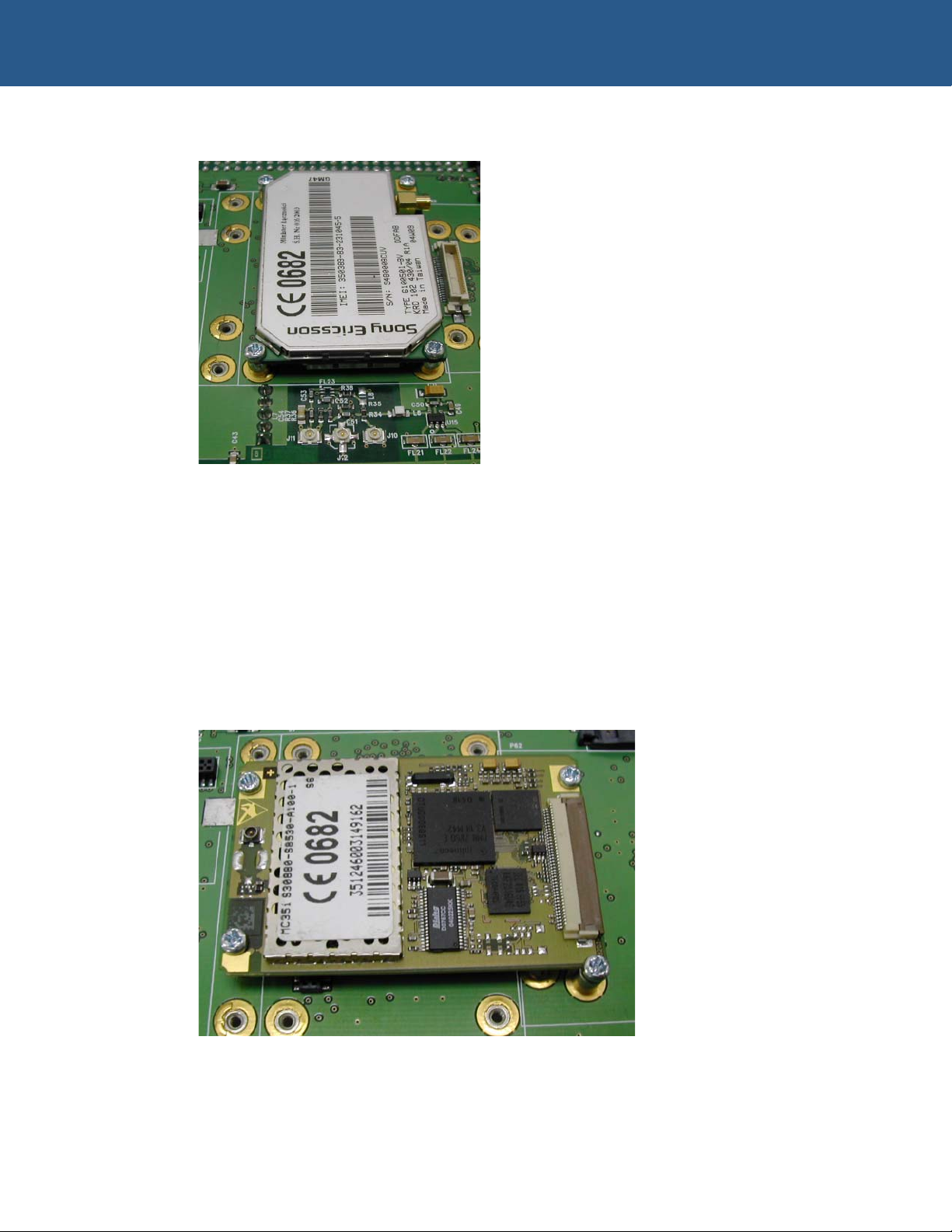
Sony Ericsson GPRS module
For worldwide cellular operations the W-E-B Telemetry board supports a Sony Ericsson
GR47 / GR48 modem module. Mounting positions, RTC supply and module interface
connector are all provided. A SIM card connector for the modem module is also
provided on the secondary side of the board. The module’s Real Time Clock back-up
function is provided by a 1.8V battery-backed power supply.
The interface to the Modem is via port 1 of the UART.
The physical address of this port is base address +08H and uses IRQ15 as the default
interrupt.
© 2005 Arcom Issue A 13
Page 14
W-E-B Telemetry Technical Manual Optional modules
The Sony Ericsson GPRS module is shown in the following photograph:
Siemens GPRS module
For worldwide cellular operations the board supports a Siemens MC35i modem module.
Mounting positions and module interface connector are all provided. A SIM card
connector for the modem module is also provided on the secondary side of the board.
The interface to the Modem module is via port 1 of the UART.
The physical address of this port is base address +08H and uses IRQ15 as the default
interrupt.
The Siemens GPRS module is shown in the following photograph:
© 2005 Arcom Issue A 14
Page 15
W-E-B Telemetry Technical Manual Optional modules
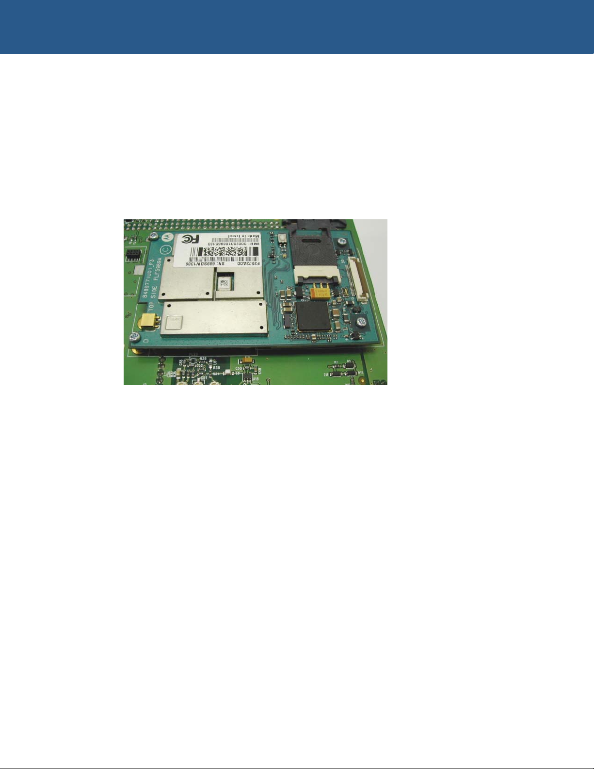
Motorola iDEN module
For American cellular operations the board supports a Nextel (Motorola) modem
module. Mounting positions and module interface connector are all provided.
The interface to the Modem module is via port 1 of the UART.
The physical address of this port is base address +08H and uses IRQ15 as the default
interrupt.
The Motorola iDEN module is shown in the following photograph:
© 2005 Arcom Issue A 15
Page 16
W-E-B Telemetry Technical Manual Optional modules
Motorola WiDEN module
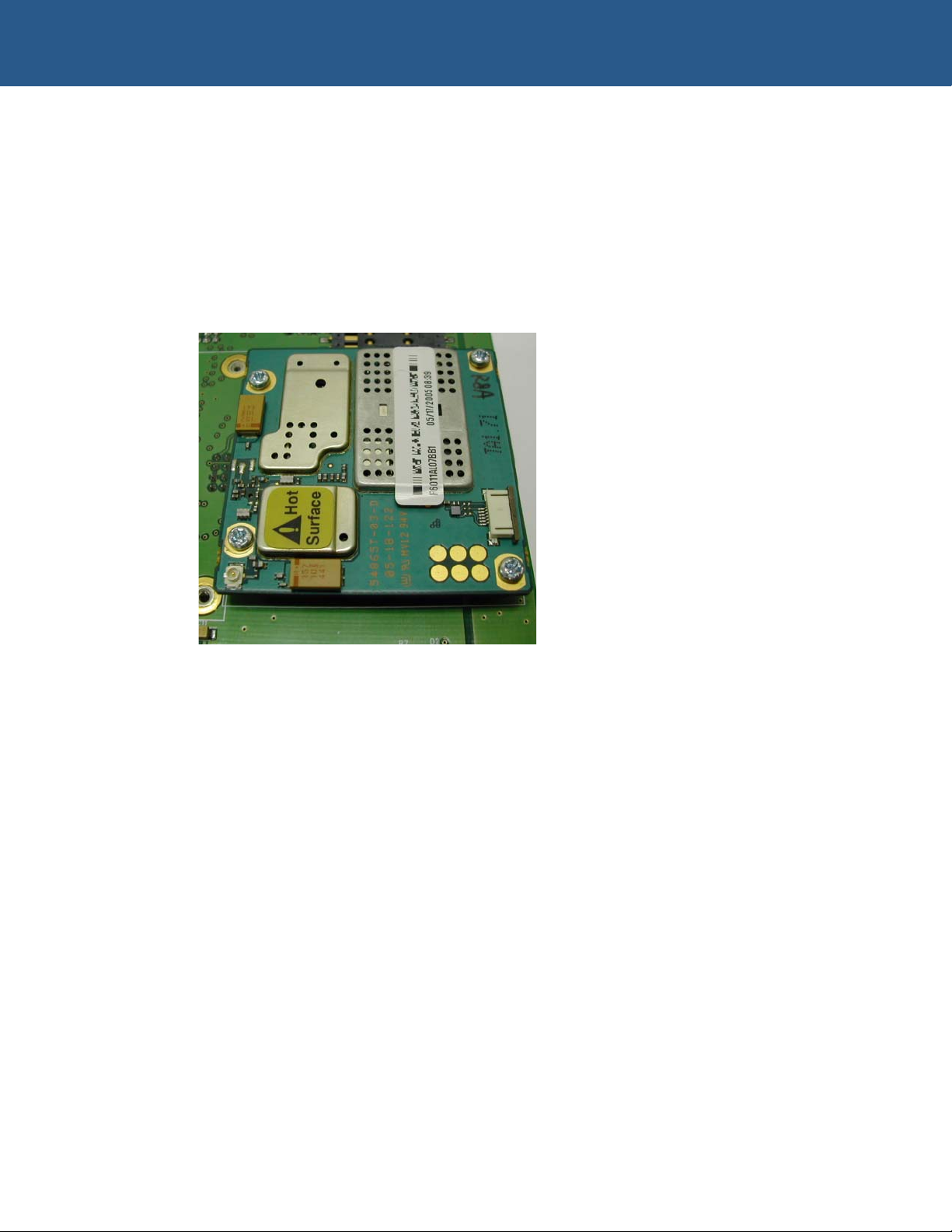
The PCB also supports a Nextel (Motorola) WiDEN module. Mounting positions and
module interface connector are all provided. The interface to the modem module is via
port 1 of the UART.
The physical address of this port is base address +08H and uses IRQ15 as the default
interrupt.
The Motorola WiDEN module is shown in the following photograph:
© 2005 Arcom Issue A 16
Page 17
W-E-B Telemetry Technical Manual Board configuration
Board configuration
Jumpers
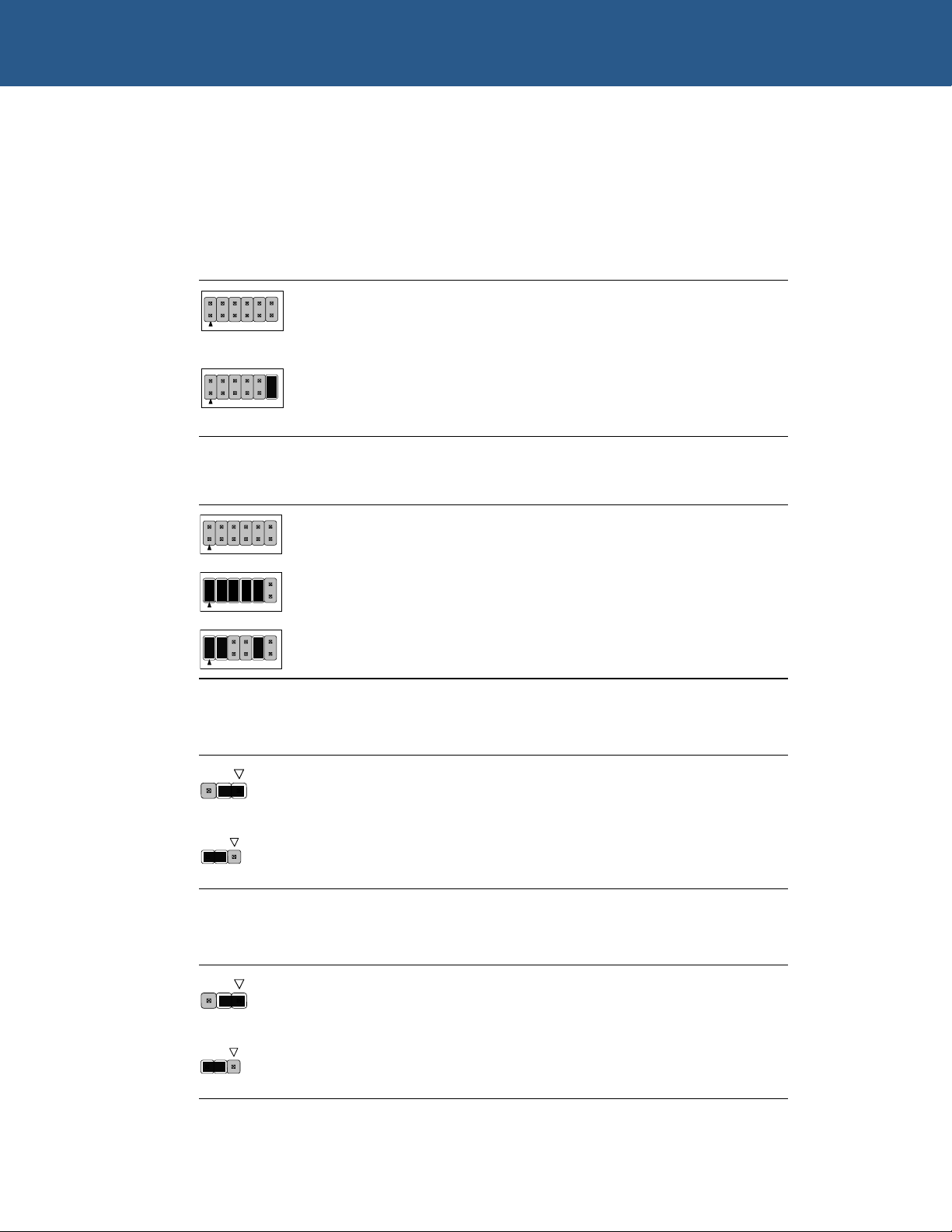
LK1 – Base address & IRQ selector
Link Description
Modem IRQ = IRQ15.
GPS IRQ = 6.
Parallel port IRQ = 12.
Modem IRQ = IRQ11.
GPS IRQ = 6.
Parallel port IRQ = 12.
Link Description
LK2 – GSM module select
Link Description
W1 – Ignition Sense enable
Base address of W-E-B Telemetry PCB set to 0x3E0.
Base address of W-E-B Telemetry PCB set to 0x0.
Base address of W-E-B Telemetry PCB set to 0x180.
Siemens modem module fitted.
Sony Ericsson modem module fitted.
Link Description
Ignition Sense enabled.
Ignition Sense disabled.
© 2005 Arcom Issue A 17
Page 18

W-E-B Telemetry Technical Manual Equipment you will need
Equipment you will need
Supplied equipment
The W-E-B Telemetry package includes the following components:
W-E-B Telemetry board. •
•
W-E-B Telemetry CD, including documentation.
What you will need
In addition to the W-E-B Telemetry package, you will need the following hardware:
•
Power supply.
•
Modem module with network connection (optional).
•
Trimble GPS module (optional).
•
Antennas.
•
RS-232 null modem cable.
•
Test computer with RS-232 communication port and Ethernet.
•
Processor card with PC/104 bus support conforming to IEEE996.1.
The board has been designed for applications using Arcom’s low power PC/104
processor boards, such as the XScale based VIPER
PEGASUS
and AIM104-386EX.
and VULCAN, or x86 compatible
© 2005 Arcom Issue A 18
Page 19

W-E-B Telemetry Technical Manual Memory map
Memory map
Address Function
180h – 187h Chip select for Trimble GPS module.
188h – 18Fh Chip select for Modem module.
190h – 194h Chip select for UART & parallel port.
The 180h address indicated above is the default address and is set at time of
manufacture. See Jumpers
physical base address.
, page 17, for information about changing the
© 2005 Arcom Issue A 19
Page 20

W-E-B Telemetry Technical Manual Ports and connectors
Ports and connectors
There are 21 connectors for accessing external devices:
Connector Function See page…
J1 DC input supply. 21
J2 Ethernet output. 21
J3 Siemens interface. 21
J4 Ethernet input. 21
J5 Lithium battery. 22
J6 Serial COMS input. 23
J7 Sony Ericsson interface 24
J8 SIM card connector. 25
J9 Ethernet LED interface. 25
J10 iO200 antenna interface. 25
J11 iO200 CELL antenna interface. 26
J12 iO200 GPS antenna interface. 26
J17 Auxiliary power output. 26
J18 iO200 PTT interface. 27
J19 iO200 SIM interface. 27
P2 iO1500 interface. 27
P3 GPS interface. 28
P4 PLD program interface. 29
P5 Serial COMS output. 23
P60, 61 PC/104 bus connectors. 29
P62 iO200 interface. 30
© 2005 Arcom Issue A 20
Page 21
W-E-B Telemetry Technical Manual Ports and connectors
J1 (Power connection)
Mating connector: Molex 09-91-0300
Mating crimp: Molex 08-50-0106.
The pin assignments for the power connection are as follows:
Pin Signal name
1 Negative
2 Positive
3 I (Ignition)
J2 (Ethernet LAN connection) and J4 (Ethernet from processor card)
The pin assignments for J2 and J4 connections are as follows:
Pin Signal name
1 Transmit +
2 Transmit -
3 Receive +
4 Reserved
5 Reserved
6 Receive -
7 Reserved
8 Reserved
J3 (Siemens modem interface)
Mating cable: FFC0.50A40/0070L5.0-5.0-10.0-10.0SABB.
Manufacturer: Tyco.
The UART connected to this interface is a 5V device. A buffer is used as a
voltage translator. This buffer is powered by VOUT.
The pin assignments for J3 connections are as follows:
© 2005 Arcom Issue A 21
Page 22

W-E-B Telemetry Technical Manual Ports and connectors
Pin Signal name Pin Signal name
1 +3.6VDC 2 +3.6VDC
3 +3.6VDC 4 +3.6VDC
5 +3.6VDC 6 Ground (0v)
7 Ground (0v) 8 Ground (0v)
9 Ground (0v) 10 Ground (0v)
11 NC 12 NC
13 +VOUT 14 NC
15 ON/OFF 16 MDM DSR
17 MDM RI 18 MDM RXD
19 MDM CTS 20 MDM RTS
21 MDM DCD 22 MDM TXD
23 NC 24 SIMPRES
25 SIMRST 26 SIMDATA
27 SIMCLK 28 SIMVCC
29 SIMGND 30 +VBAT
31 NC 32 NC
33 NC 34 NC
35 NC 36 NC
37 NC 38 NC
39 NC 40 NC
J5 (Lithium battery output)
Mating connector: Molex 50-57-9702.
Mating crimp: Molex 16-02-0104.
The pin assignments for J5 connection are as follows:
Pin Signal name
1 +3.6v
2 0v
J5 is directly connected to the lithium battery.
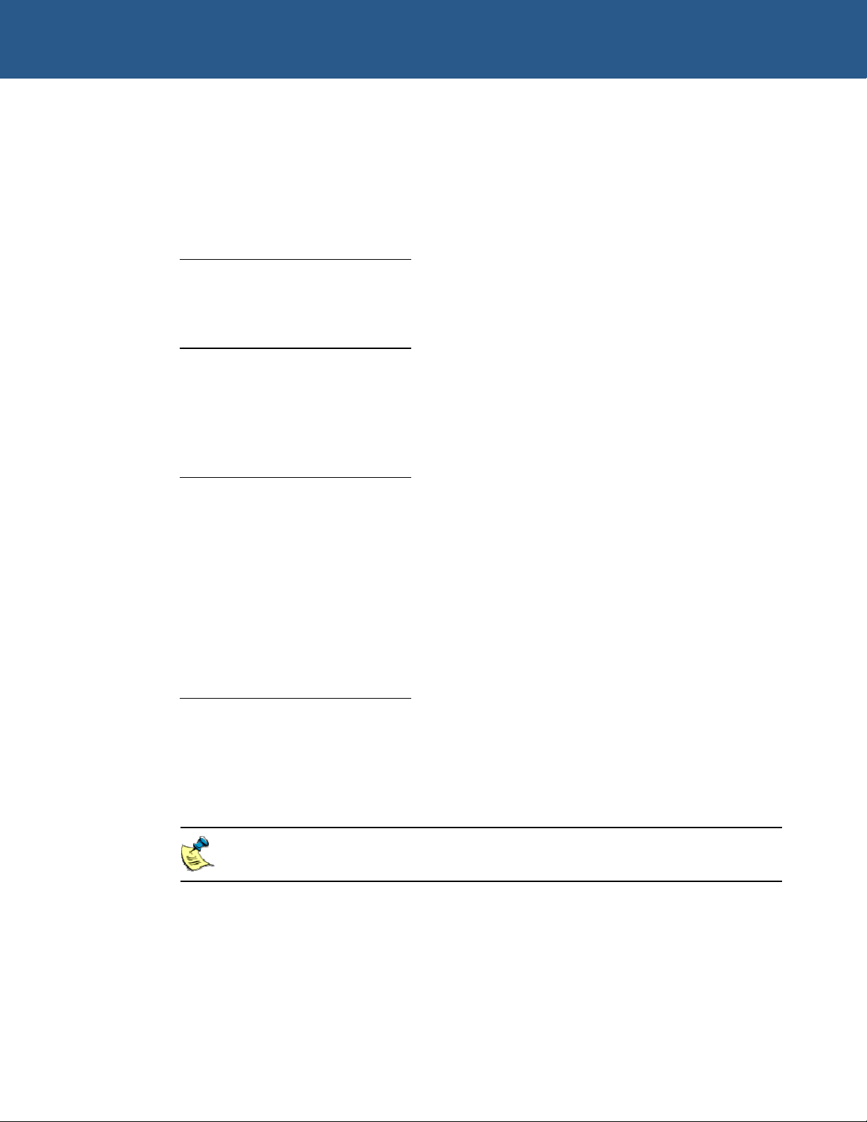
Any equipment connected to J5 must include battery protection equipment
(current limit resistor, reverse voltage protection).
© 2005 Arcom Issue A 22
Page 23

W-E-B Telemetry Technical Manual Ports and connectors
P5 (COM0 & COM1, RS-232)
Pin assignments for the serial ports are as follows.
Pin Signal name Pin Signal name
1T DCD1 1B DCD0
2T RXD1 2B RXD0
3T TXD1 3B TXD0
4T DTR1 4B DTR0
5T Ground (0v) 5B Ground (0v)
6T DSR1 6B DSR0
7T RTS1 7B RTS0
8T CTS1 8B CTS0
9T RI1 9B RI0
J6 (COM0 & COM1 from processor card)
Mating Connector: 3M Ref number 3421-6600
Pin assignments for the serial ports are as follows:
Pin Signal name Pin Signal name
1 DCD0 2 DSR0
3 RXD0 4 RTS0
5 TXD0 6 CTS0
7 DTR0 8 RI0
9 Ground0 (0v) 10 No connect
11 DCD1 12 DSR1
13 RXD1 14 RTS1
15 TXD1 16 CTS1
17 DTR1 18 RI1
19 Ground1 (0v) 20 No connect
© 2005 Arcom Issue A 23
Page 24

W-E-B Telemetry Technical Manual Ports and connectors
J7 (Sony Ericsson modem interface)
Pin assignments for the Sony Ericsson modem interface are as follows:
Pin Signal name Pin Signal name
1 +3.6VDC 2 Ground (0v)
3 +3.6VDC 4 Ground (0v)
5 +3.6VDC 6 Ground (0v)
7 +3.6VDC 8 Ground (0v)
9 +3.6VDC 10 Ground (0v)
11 NC 12 Ground (0v)
13 NC 14 ON/OFF
15 SIMVCC 16 SIMPRES
17 SIMRST 18 SIMDATA
19 SIMCLK 20 NC
21 NC 22 NC
23 NC 24 NC
25 VBAT 26 NC
27 NC 28 NC
29 NC 30 NC
31 NC 32 MDM DSR
33 NC 34 +VOUT
35 NC 36 MDM RI
37 MDM DTR 38 MDM DCD
39 MDM RTS 40 MDM CTS
41 MDM TXD 42 MDM RXD
43 NC 44 NC
45 NC 46 +VOUT
47 NC 48 NC
49 NC 50 NC
51 NC 52 NC
53 NC 54 NC
55 NC 56 NC
57 NC 58 NC
59 NC 60 NC
© 2005 Arcom Issue A 24
Page 25

W-E-B Telemetry Technical Manual Ports and connectors
J8 (SIM card connector)
Pin assignments for the SIM card are as follows:
Pin Signal name
1 Vcc
2 Reset
3 Clock
4 Data
5 N.C
6 Ground (0v)
7 Switch N.O
8 Switch Com
J9 (Ethernet LEDs)
Mating connector: Neltron 2418HJ-02-PHD.
Mating connector crimps (x3): Neltron 2418TJ-PHD
Pin assignments for the Ethernet LEDs are as follows:
Pin Signal name
1 N.C
2 100 BaseT
3 N.C
4 10 BaseT
5 N.C
6 Activity
J10 (iO200 modem antenna interface)
Pin assignments for the U.FL style connector are as follows:
Pin Signal name
Center pin RF Signal
Ring RF Ground
© 2005 Arcom Issue A 25
Page 26

W-E-B Telemetry Technical Manual Ports and connectors
J11 (iO200 modem CELL antenna interface)
Pin assignments for the U.FL style connector are as follows:
Pin Signal name
Center pin RF Signal
Ring RF Ground
J12 (iO200 modem GPS antenna interface)
Pin assignments for the U.FL style connector are as follows:
Pin Signal name
Center pin RF Signal
Ring RF Ground
J17 (Auxiliary power)
Mating connector: Molex 22 01 2055.
Mating connector crimps (x5): Molex 08 50 0032.
Pin assignments for the auxiliary power are as follows:
Pin Signal name
1 +5v
2 +3.6v
3 +12v
4 Ground (0v)
5 -12v
© 2005 Arcom Issue A 26
Page 27

W-E-B Telemetry Technical Manual Ports and connectors
J18 (iO200 modem Push To Talk - PTT)
Mating connector: Molex 22 01 2055.
Mating connector crimps (x5): Molex 08 50 0032.
Pin assignments for PTT are as follows.
Pin Signal name
1 Speaker out
2 Microphone in
3 PTT Switch
4 +5v
5 Ground (0v)
J19 (iO200 modem SIM card interface)
Mating cable: FFC0.50A06/0050L5.0-5.0-10.0-10.0SABB
Manufacturer: Tyco.
Pin assignments for the SIM card interface are as follows:
Pin Signal name
1 RESET
2 VCC
3 Ground (0v)
4 DATA
5 Ground (0v)
6 CLOCK
P2 (iO1500 modem interface)
Mating cable: FFC0.50A30/0050L5.0-5.0-10.0-10.0SABB.
Pin assignments for the iO1500 modem interface are as follows:
Pin Signal name Pin Signal name
1 DMTXD 2 MDM RXD
3 MDM DTR 4 MDM DCD
5 GND 6 MDM RTS
© 2005 Arcom Issue A 27
continued…
Page 28

W-E-B Telemetry Technical Manual Ports and connectors
Pin Signal name Pin Signal name
7 MDM CTS 8 MDM DSR
9 MDM RI 10 NC
11 NC 12 NC
13 NC 14 NC
15 NC 16 +VOUT
17 ON/OFF 18 PROG
19 +3.6VDC 20 +3.6VDC
21 +3.6VDC 22 +3.6VDC
23 +3.6VDC 24 NC
25 NC 26 Ground (0v)
27 Ground (0v) 28 Ground (0v)
29 Ground (0v) 30 Ground (0v)
P3 (GPS interface)
Pin assignments for the GPS interface are as follows:
Pin Signal name
1 GPS TX
2 Ground (0v)
3 GPS RX
4 PPS
5 N.C
6 N.C
7 +3.6v
The UART connected to this interface is a 5V device. A buffer is used as a
voltage translator. VOUT is used to power this buffer.
The modem is a DCE device software.
8 VBAT
© 2005 Arcom Issue A 28
Page 29

W-E-B Telemetry Technical Manual Ports and connectors
P4 (PLD Program Header)
Mating connector: Lattice program.
Cable: Available only from Lattice Semiconductors.
Pin assignments for the PLD header are as follows:
Pin Signal name
1 Ground (0v)
2 SDO
3 /ISPEN
4 MODE
5 SDI
6 CLK
7 N.C
8 N.C
9 +5V
10 Ground (0v)
P60,61 PC/104 bus connectors)
Pin assignments for the PC/104 bus are as follows:
Pin Row A Row B Row C Row D
0 - Ground Ground
1 /IOCHCK Ground /SBHE /MEMCS16
2 D7 RSTDRV LA23 /IOCS16
3 D6 +5V LA22 IRQ10
4 D5 IRQ9 LA21 IRQ11
5 D4 N.C LA20 IRQ12
6 D3 DRQ2 LA19 IRQ15
7 D2 -12V LA18 IRQ14
8 D1 /ENDXFR LA17 /DACK0
9 D0 +12V /MEMR DRQ0
10 IOCHRDY KEY /MEMW /DACK5
11 AEN /SMEMW D8 DRQ5
© 2005 Arcom Issue A 29
continued…
Page 30

W-E-B Telemetry Technical Manual Ports and connectors
Pin Row A Row B Row C Row D
12 A19 /SMEMR D9 /DACK6
13 A18 /IOW D10 DRQ6
14 A17 /IOR D11 /DACK7
15 A16 /DACK3 D12 DRQ7
16 A15 DRQ3 D13 +5V
17 A14 DACK1 D14 MASTER
18 A13 DRQ1 D15 Ground
19 A12 /REFRESH KEY Ground
20 A11 SYSCLK - -
21 A10 IRQ7 - -
22 A9 IRQ6 - -
23 A8 IRQ5 - -
24 A7 IRQ4 - -
25 A6 IRQ3 - -
26 A5 /DACK2 - -
27 A4 TC - -
28 A3 BALE - -
29 A2 +5V - -
30 A1 OSC - -
31 A0 Ground - -
32 Ground Ground - -
P62 (iO200 modem interface)
Pin assignments for the iO200 modem interface are as follows:
Pin Signal name Pin Signal name
1 SPKR POS 2 SPKR NEG
3 MIC POS 4 MIC NEG
5 ON/OFF 6 HOST WAKE UP
7 RESERVED 8 FIRMWARE UPLOAD EN
9 RESERVED 10 OPTION SELECT 1
© 2005 Arcom Issue A 30
continued…
Page 31

W-E-B Telemetry Technical Manual Ports and connectors
Pin Signal name Pin Signal name
11 OPTION SELECT 2 12 RESERVED
13 RESERVED 14 VOUT
15 RED STATUS LED 16 GREEN STATUS LED
17 CTS2 18 RTS2
19 TXD2 20 RXD2
21 RI 22 CDI
23 CTS 24 RTS
25 DTR 26 DSR
27 TXD1 28 RXD1
29 RESERVED 30 RESERVED
31 VBAT 32 Ground (0v)
33 VBAT 34 Ground (0v)
35 VBAT 36 Ground (0v)
37 VBAT 38 Ground (0v)
39 VBAT 40 Ground (0v)
The UART connected to this interface is a 5v device, a buffer is used as a
voltage translator. VOUT is used to power this buffer
The modem is a DCE device.
© 2005 Arcom Issue A 31
Page 32

W-E-B Telemetry Technical Manual Antenna considerations
Antenna considerations
The antenna must be mounted like any other cellular or land mobile radio antenna. For
vehicle applications the best position is usually the center of the vehicle roof, which
provides a fairly symmetric ground plane.
Use this information to help assist you in selecting the appropriate antenna for your
product
Antenna safety
The following statement from the American National Standards Institute (ANSI)
specifies the safety criteria that integrators must use when designing products with
radiating elements:
“The design of the integrated product must be such that the location used and the other
particulars of the antenna comply with the ANSI guidelines concerning Radio
Frequency Energy Exposure and with any other nationally recognized radio frequency
standards that may be applicable thereto.”
For mobile operation with an external antenna, the modem module must be
installed in a manner that provides a minimum separation distance of 300mm
(12”) or more between the antenna and all persons, in order to satisfy FCC RF
exposure requirements for mobile transmitting.
These safety precautions must be observed during all phases of operation.
Manufacturers of cellular terminal equipment are advised to convey the following safety
information:
When in a hospital or health care facility, observe the restrictions on the use of
•
mobiles. Observe the guidelines posted; medical equipment may be sensitive to RF
energy.
• • Switch off cellular equipment before boarding an aircraft. Make sure it cannot be
turned on inadvertently. The operation of wireless appliances in an aircraft is
forbidden.
Do not operate cellular equipment in the presence of flammable gases or fumes.
Switch off cellular equipment when near petrol stations, fuel depots, chemical plants
or where blasting operations are in progress. Operation of electrical equipment in
potentially explosive atmospheres can constitute a safety hazard.
© 2005 Arcom Issue A 32
Page 33

W-E-B Telemetry Technical Manual Antenna considerations
ESD protection
In order to protect the modem modules against ESD damage it is recommended that
only rubber-coated antennas are used.
Antenna performance
Typically, the network operator sets the antenna network requirements.
© 2005 Arcom Issue A 33
Page 34

W-E-B Telemetry Technical Manual Appendix A - Contacting Arcom
Appendix A - Contacting Arcom
Arcom sales
Arcom’s sales team is always available to assist you in choosing the board that best
meets your requirements. Contact your local sales office or hotline.
Sales office US Sales office UK
Arcom
7500W 161
Overland Park
Kansas
66085
USA
Tel: 913 549 1000
Fax: 913 549 1002
E-mail: [email protected]
Comprehensive information about our products is available from our web sites:
www.arcom.com
st
Street
and www.arcom.co.uk.
While Arcom’s sales team can assist you in making your decision, the final
choice of boards or systems is solely and wholly the responsibility of the buyer.
Arcom’s entire liability in respect of the boards or systems is as set out in
Arcom’s standard terms and conditions of sale. If you intend to write your own
low level software, you can start with the source code on the disk supplied. This
is example code only to illustrate use on Arcom’s products. It has not been
commercially tested. No warranty is made in respect of this code and Arcom
shall incur no liability whatsoever or howsoever arising from any use made of
the code.
Arcom
Clifton Road
Cambridge
CB1 7EA
UK
Technical support
Arcom has a team of technical support engineers available to provide a quick and free
response to your technical queries.
Technical support US Technical support UK
Tel: 913 549 1010
Fax: 913 549 1001
E-mail: [email protected]
© 2005 Arcom Issue A 34
Tel: +44 (0)1223 412 428
Fax: +44 (0)1223 403 409
E-mail: [email protected]
Page 35

W-E-B Telemetry Technical Manual Appendix B - Technical specifications
Appendix B - Technical specifications
W-E-B Telemetry
Power
Input power: 10 - 30V DC.
Overvoltage/reverse
voltage protection: 100V DC.
Ignition sense input: 12V DC protected.
Power consumption: 8 Watts (excluding GPS).
Environmental
Humidity: 5% to 95% RH (non-condensing).
Temperature: Operating: -30°C to +65°C.
Storage: -20°C to +85°C.
Weight: 0.83 kg (1.83 lbs) excluding optional cards.
GPS interface
General
Product: Lassen™ SQ GPS receiver (Trimble).
Characteristics: L1 frequency (1575.42 MHz), C/A code (Standard Positioning
Update rate: TSIP @ 1 Hz; NMEA @ 1 Hz, TAIP @ 1HZ
Trimble SQ GPS (GPS module only): 100 [email protected].
Trimble SQ GPS (w/ embedded antenna): 133 [email protected].
Service), 8-channel, continuous tracking receiver, 32
correlators.
Accuracy: Horizontal: <6 meters (50%), <9 meters (90%).
Altitude: <11 meters (50%), <18 meters (90%).
Velocity: 0.06 m/sec.
PPS: ±95 nanoseconds.
Protocols: TSIP at 9600 baud, 8 bits (selectable baud rate).
NMEA 0183 v3.0 (selectable baud rate, 8 bits).
TAIP.
NMEA messages: GGA, VTG, GLL, ZDA, GSA, GSV and RMC
Messages selectable by TSIP command
© 2005 Arcom Issue A 35
Page 36

W-E-B Telemetry Technical Manual Appendix B - Technical specifications
Acquisition
Reacquisition: <2 sec (90%).
Hot start: <14 sec (50%), <18 sec (90%).
Warm start: <38 sec (50%), <45 sec (90%).
Cold start: <90 sec (50%), <170 sec (90%).
Initialization: Cold start requires no initialization.
Warm start requires last position; time and almanac are
saved in battery back-up memory.
Hot start requires that the ephemeris also saved.
Dynamics: Acceleration: 4g (39.2m/sec2) Motional jerk: 20m/sec3.
Operational limits: Altitude <18000m or velocity <515m/s.
(COCOM limit). Either limit may be exceeded, but not both.
© 2005 Arcom Issue A 36
Page 37
W-E-B Telemetry Technical Manual Appendix C - Mechanical specifications
Appendix C - Mechanical specifications
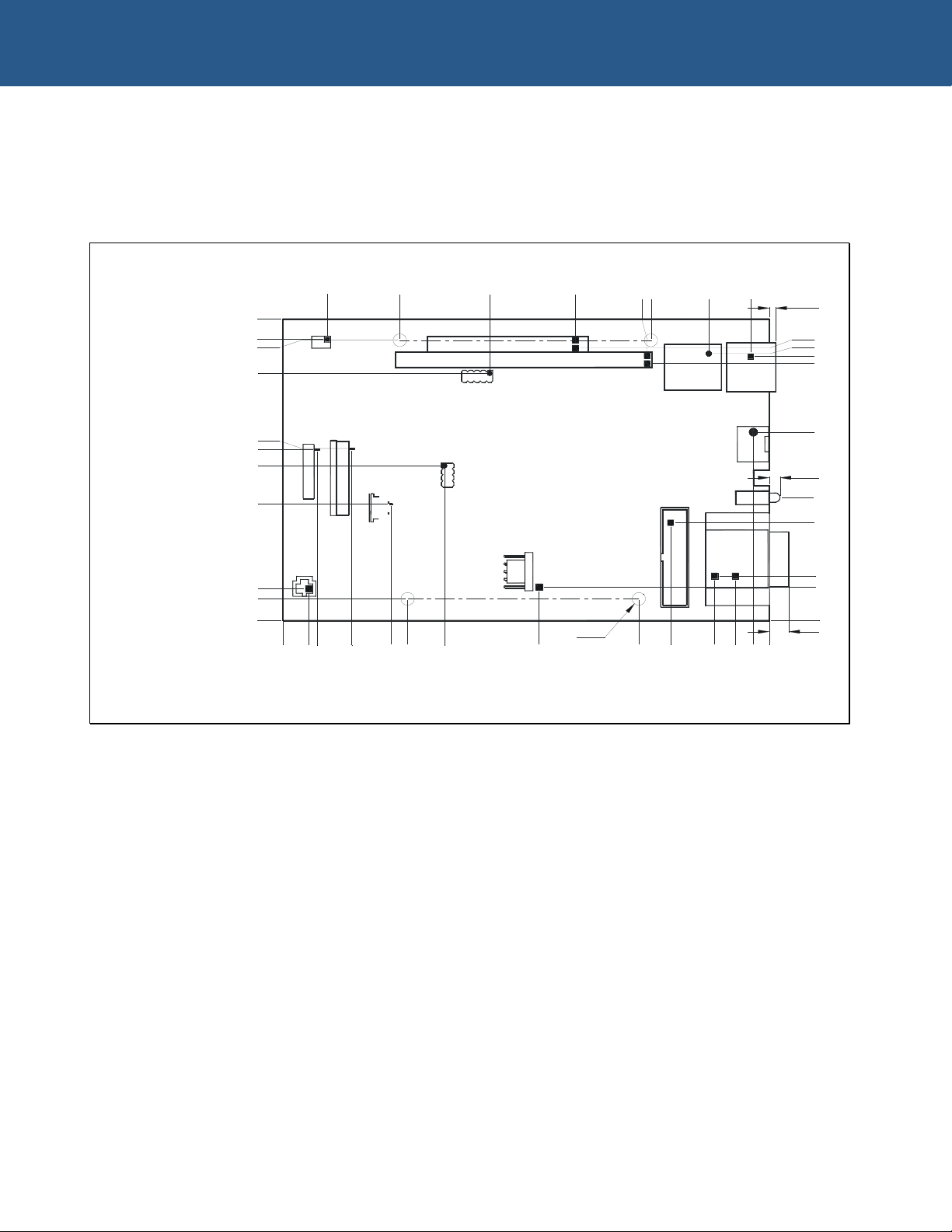
Mechanical dimensions (in mm) – primary side
PRIMARY SIDE
14.25
100.00
93.22
92.88
81.92
56.99
56.65
51.26
38.59
10.54
7.15
0.00
NOTES
1) ALL CONNECTOR DIMENSIONS ARE TAKEN FROM PIN 1
J9
P2
J3
J5
0.00
8.18
10.92
21.97
37.30
'A' 'A'
J19
'A'
39.79
34.54
65.91
P61
P60
P4
J18
J17
51.54
93.19
Ø4.22
FOUR 'A' HOLES
81.60
117.31
116.05
J6
'A'
113.44
123.56
135.77
149.05
J4
J2
J1
DS2
P5
137.57
144.15
149.94
2.05
90.34
88.44
87.56
85.26
62.41
3.42
40.74
32.39
14.78
11. 11
0.00
6.19
155.00
© 2005 Arcom Issue A 37
Page 38
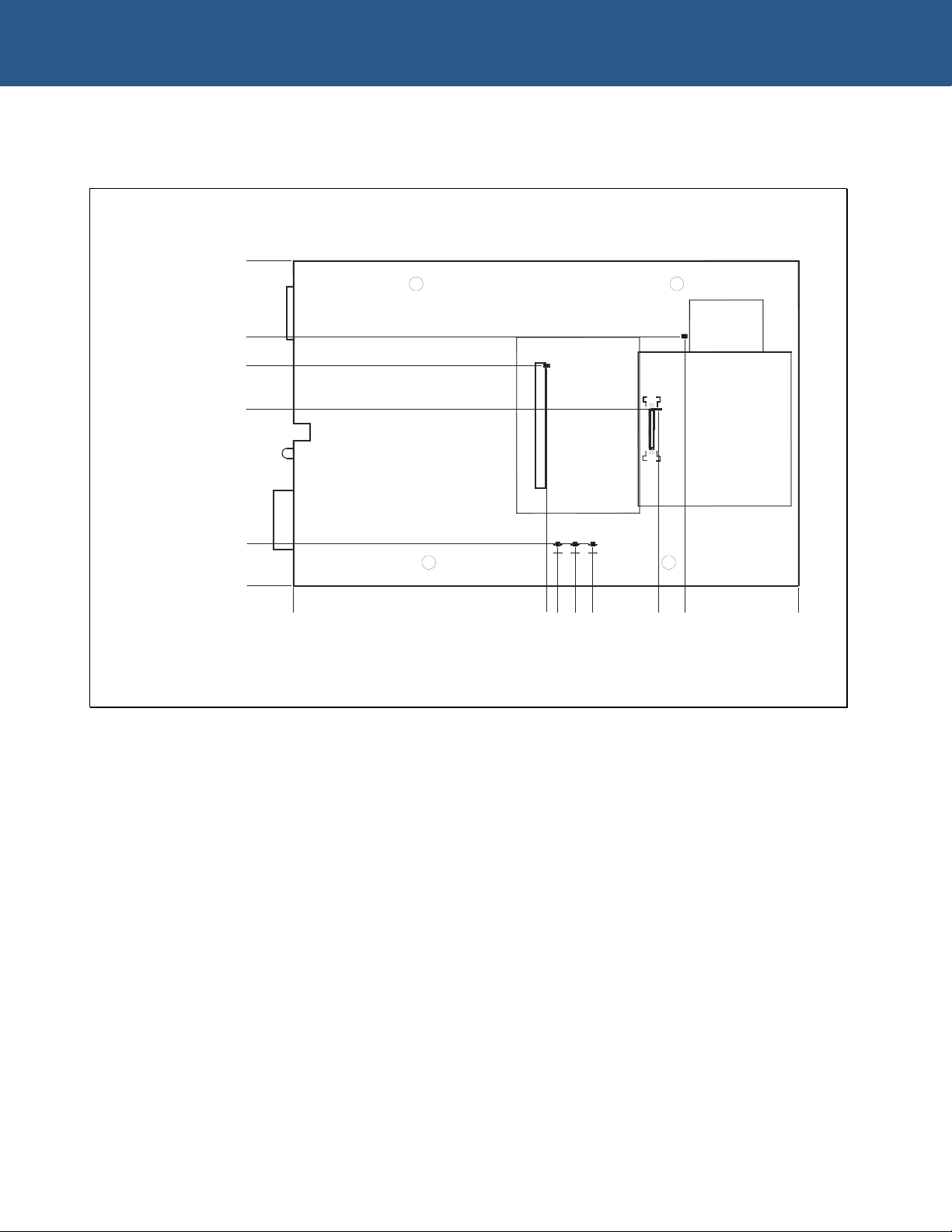
W-E-B Telemetry Technical Manual Appendix C - Mechanical specifications
Mechanical dimensions (in mm) – secondary side
SECONDARY SIDE
100.00
76.75
67.77
54.29
12.96
0.00
0.00
NOTES
1) ALL CONNECTOR DIMENSIONS ARE TAKEN FROM PIN 1
77.66
81.02
J7
86.42
J10J11 J12
91.82
112.02
120.05
J8
P62
155.00
© 2005 Arcom Issue A 38
Page 39

W-E-B Telemetry Technical Manual Index
Index
A F
accuracy, GPS · 35 features · 6
acquisition · 36
antenna · 32
ESD protection · 33
performance · 33
safety · 32
anti-static · 8
auxiliary power connector · 26
G
GPS accuracy · 35
GPS interface · 35
GPS interface port · 28
GPS protocols · 35
GSM module jumper · 17
B
background · 6
base address jumper · 17
battery · 8
connector · 22
block diagram · 9
board
configuration · 17
handling instructions · 8
overview · 7
C
circuit
ignition sense · 11
power supervisory · 11
COM0 and COM1 from processor card port · 23
COM0, COM1 and RS-232 ports · 23
components · 18
connectors · 20
contact details · 34
copyright · 2
H
hardware description · 9
hardware requirements · 18
humidity · 35
I
ignition sense circuit · 11
ignition sense enable jumper · 17
information sources · 5
initialization · 36
interface
network · 10
serial · 10
iO1500 modem interface port · 27
iO200 modem antenna interface port · 25
iO200 modem CELL antenna interface port · 26
iO200 modem GPS antenna interface port · 26
iO200 modem interface port · 30
iO200 modem push to talk PTT port · 27
iO200 modem SIM card interface port · 27
IRQ jumper · 17
D
definitions · 2
disclaimer · 2
dual UART 16C552 · 11
dynamics · 36
E
EMC · 8
environmental specifications · 35
equipment · 18
ESD protection · 33
ethernet from processor card connector · 21 J5 lithium battery output · 22
ethernet LAN connector · 21
ethernet LEDs connector · 25 J8 SIM card connector · 25
external device connectors · 20
J
J1 power connection · 21
J10 iO200 modem antenna interface · 25
J11 iO200 modem CELL antenna interface · 26
J12 iO200 modem GPS antenna interface · 26
J17 auxiliary power · 26
J18 iO200 modem push to talk PTT · 27
J19 iO200 modem SIM card interface · 27
J2 ethernet LAN connector · 21
J3 Siemens modem interface connector · 21
J4 ethernet from processor card connector · 21
J6 COM0 and COM1 from processor card · 23
J9 ethernet LEDs · 25
© 2005 Arcom Issue A 39
Page 40

W-E-B Telemetry Technical Manual Index
L
LAN · 21
LEDs · 12
lithium battery output connector · 22
LK1 jumper · 17
LK2 jumper · 17
M
mechanical specifications · 37
memory map · 19
modem on/off control signal · 11
module
Motorola iDEN · 15
Motorola WiDEN · 16
Siemens GPRS · 14
Sony Ericsson GPRS · 13
Trimble GPS · 13
Motorola iDEN module · 15
Motorola WiDEN module · 16
N
network interface · 10
NMEA · 35
O
optional modules · 13
R
requirements, hardware · 18
S
serial interface · 10
serial ports · 23
Siemens GPRS module · 14
Siemens modem interface connector · 21
SIM card connector · 25
Sony Ericsson GPRS module · 13
source code · 34
specifications
mechanical · 37
technical · 35
static · 8
status LEDs · 12
support,contact information · 34
switch mode power supplies · 10
symbols · 5
T
technical
specifications · 35
support · 34
temperature · 35
trademarks · 2
Trimble GPS module · 13
P
P2 iO1500 modem interface · 27
P3 GPS interface · 28
P4 PLD program header · 29
P5 COM0, COM1, RS-232 ports · 23
P60 and P61 PC104 bus connectors · 29
P62 iO200 modem interface · 30
packaging · 8
PC/104 bus connectors · 29
PC104 bus support · 10
PLD program header port · 29
ports · 20
serial · 23
power
conditioning · 10
connector · 21
consumption · 35
input · 35
specifications · 35
supervisory circuit · 11
supply requirements · 10
protocols, GPS · 35
U
update rate · 35
V
voltage · 35
W
W1 jumper · 17
warranty · 2
W-E-B Telemetry
block diagram · 9
overview · 7
weight · 35
© 2005 Arcom Issue A 40
 Loading...