

Page 1
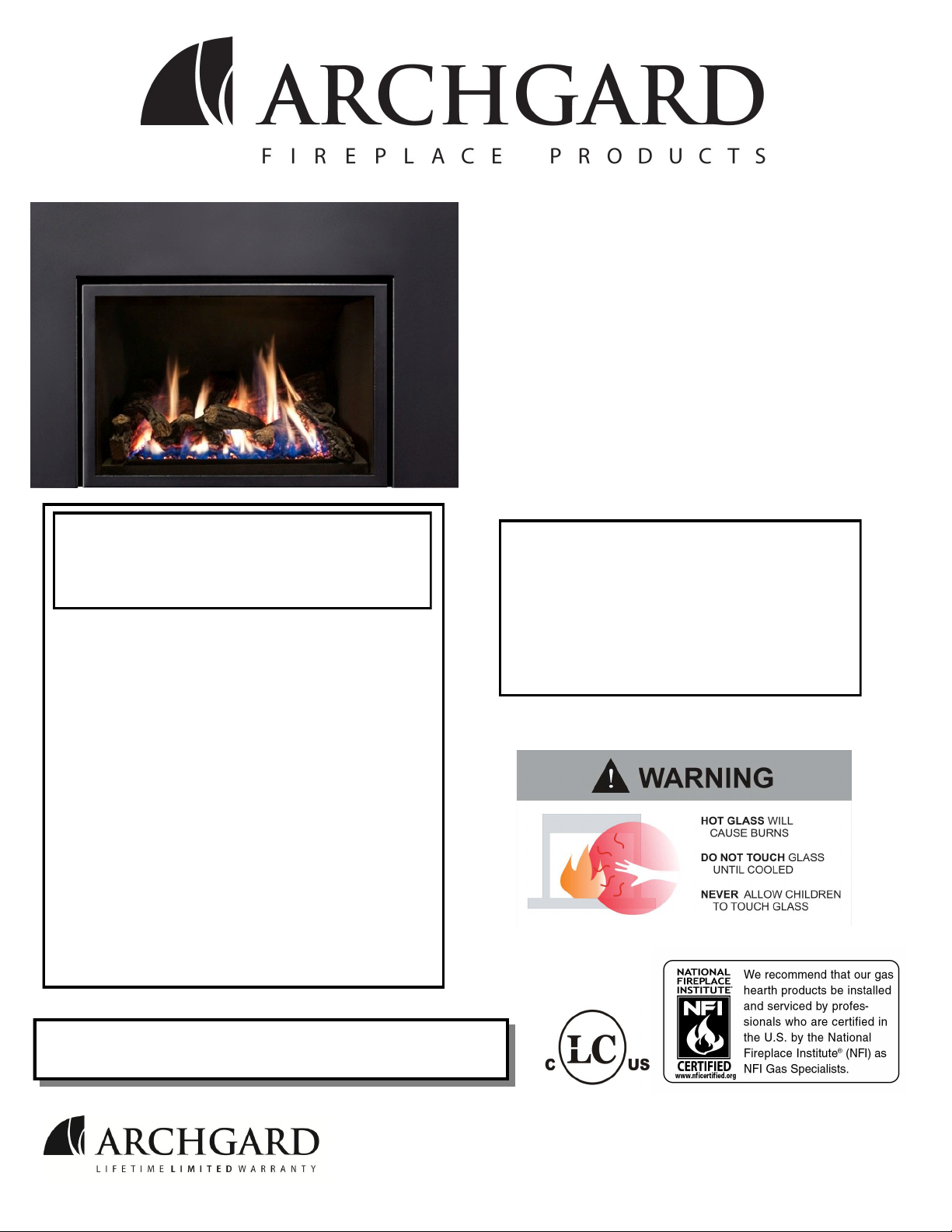
31-DVIE33
Gas Fired Vented Room
Heater (Direct Vent)
S/N 211061And up
USERS’ INSTALLATION
OPERATION and
MAINTENANCE MANUAL
WARNING: If the information in this manual is
not followed exactly, a fire or explosion may
result causing property damage, personal
injury or loss of life.
Do not store or use gasoline or other flammable
vapors and liquids in the vicinity of this or any
other appliance.
WHAT TO DO IF YOU SMELL GAS:
Do not try to light any appliance.
Do not touch any electrical switch; do not use
any phone in your building.
Immediately call your gas supplier from a
neighbor’s phone. Follow the gas supplier’s
instructions.
If you cannot reach your gas supplier, call the
fire department.
Installation and service must be performed by a
qualified installer, service agency or the gas
supplier.
This appliance may be installed in an aftermarket
permanently located, manufactured home (USA
only) or mobile home, where not prohibited by
local codes.
This appliance is only for use with the type
of gas indicated on the rating plate. This
appliance is not convertible for use with other
gases, unless a certified kit is used.
*Conversion kit required for Propane use
Tested and
listed by
INSTALLER: Leave this manual with the appliance.
CONSUMER: Retain this manual for future reference.
7116 Beatty Dr
Mission, BC V2V 6B4
Canada
LABTEST Certification Inc
Richmond, British Columbia
ANSI Z21.88-2009/CSA 2.33-2009
200-1131
March 2013
Page 2

31-DVIE33 2
STATE OF MASSACHUSETTS REQUIREMENTS
5.08: Modifications to NFPA-54, Chapter 10
(2) Revise 10.8.3 by adding the following additional requirements:
(a) For all side wall horizontally vented gas fueled equipment installed in every dwelling, building or structure used in whole or in part
for residential purposes, including those owned or operated by the Commonwealth and where the side wall exhaust vent termination is
less than seven (7) feet above finished grade in the area of the venting, including but not limited to decks and porches, the following
requirements shall be satisfied:
1. INSTALLATION OF CARBON MONOXIDE DETECTORS. At the time of installation of the side wall horizontal vented gas fueled
equipment, the installing plumber or gasfitter shall observe that a hard wired carbon monoxide detector with an alarm and battery backup is installed on the floor level where the gas equipment is to be installed. In addition, the installing plumber or gasfitter shall observe
that a battery operated or hard wired carbon monoxide detector with an alarm is installed on each additional level of the dwelling, building or structure served by the side wall horizontal vented gas fueled equipment. It shall be the responsibility of the property owner to
secure the services of qualified licensed professionals for the installation of hard wired carbon monoxide detectors
a. In the event that the side wall horizontally vented gas fueled equipment is installed in a crawl space or an attic, the hard wired carbon
monoxide detector with alarm and battery back-up may be installed on the next adjacent floor level.
b. In the event that the requirements of this subdivision can not be met at the time of completion of installation, the owner shall have a
period of thirty (30) days to comply with the above requirements; provided, however, that during said thirty (30) day period, a battery
operated carbon monoxide detector with an alarm shall be installed.
2. APPROVED CARBON MONOXIDE DETECTORS. Each carbon monoxide detector as required in accordance with the above provisions shall comply with NFPA 720 and be ANSI/UL 2034 listed and IAS certified.
3. SIGNAGE. A metal or plastic identification plate shall be permanently mounted to the exterior of the building at a minimum height of
eight (8) feet above grade directly in line with the exhaust vent terminal for the horizontally vented gas fueled heating appliance or
equipment. The sign shall read, in print size no less than one-half (1/2) inch in size, "GAS VENT DIRECTLY BELOW. KEEP
CLEAR OF ALL OBSTRUCTIONS".
4. INSPECTION. The state or local gas inspector of the side wall horizontally vented gas fueled equipment shall not approve the installation unless, upon inspection, the inspector observes carbon monoxide detectors and signage installed in accordance with the provisions
of 248 CMR 5.08(2)(a)1 through 4.
(b) EXEMPTIONS: The following equipment is exempt from 248 CMR 5.08(2)(a)1 through 4:
1. The equipment listed in Chapter 10 entitled "Equipment Not Required To Be Vented" in the most current edition of NFPA 54 as
adopted by the Board; and
2. Product Approved side wall horizontally vented gas fueled equipment installed in a room or structure separate from the dwelling,
building or structure used in whole or in part for residential purposes.
(c) MANUFACTURER REQUIREMENTS - GAS EQUIPMENT VENTING SYSTEM PROVIDED. When the manufacturer of Product Approved side wall horizontally vented gas equipment provides a venting system design or venting system components with the
equipment, the instructions provided by the manufacturer for installation of the equipment and the venting system shall include:
1. Detailed instructions for the installation of the venting system design or the venting system components; and
2. A complete parts list for the venting system design or venting system.
(d) MANUFACTURER REQUIREMENTS - GAS EQUIPMENT VENTING SYSTEM NOT PROVIDED. When the manufacturer of a
Product Approved side wall horizontally vented gas fueled equipment does not provide the parts for venting the flue gases, but identifies
"special venting systems", the following requirements shall be satisfied by the manufacturer:
1. The referenced "special venting system" instructions shall be included with the appliance or equipment installation instructions; and
2. The "special venting systems" shall be Product Approved by the Board, and the instructions for that system shall include a parts list
and detailed installation instructions.
(e) A copy of all installation instructions for all Product Approved side wall horizontally vented gas fueled equipment, all venting instructions, all parts lists for venting instructions, and/or all venting design instructions shall remain with the appliance or equipment at
the completion of the installation.
For the State of Massachusetts, installation and repair must be done by a plumber or gasfitter li-
censed in the Commonwealth of Massachusetts.
For the State of Massachusetts, flexible connectors shall not exceed 36 inches in length.
The State of Massachusetts requires the installation of a carbon monoxide alarm in accordance
with NFPA 720 and a CO alarm with battery back up in the same room where the gas appliance is
installed.
For the State of Massachusetts the appliances individual shut – off must be a t-handle type valve.
Page 3
31-DVIE33 3
INTRODUCTION
Congratulations on choosing an Archgard Gas Fireplace!
The 31-DVIE33 is one of the most advanced Direct Vent Insert heaters available today. It is
solidly designed using the latest technology and manufactured to the highest quality. It is our
aim to provide you with an appliance for many trouble-free years of reliable service.
Some of the many features of your 31-DVIE33 are:
Heater Classification The 31-DVIE33 is classified as a heating appliance.
Therefore, it uses Direct Vent safety technology and it is
suitable for continuously operated zone heating.
High Efficiency The 31-DVIE33 has one of the highest efficiencies of any
Direct Vent gas insert, which means that it is less expensive
to operate.
Adjustable Fan Speed Each 31-DVIE33 comes complete with 6 level adjustable
speed controlled circulation fan.
Adjustable Flame The flame aesthetics and heat output can be adjusted to suit
the owner’s liking and heating needs.
Solid Construction The 31-DVIE33 is mainly constructed of 16 and 18 gauge
galvanized and aluminized coated steel for long life and
durability.
Optional Accessories Check with your Authorized Archgard Dealer for a full
complement of decorative accessories to suit your home’s
décor and your tastes.
Electronic Control System The 31-DVIE33 uses a gas control valve that is operated by a
Multifunction Remote Control. It can be used as either an
Intermittent or Standing Pilot system.
Fireplace Model Number: 31-DVIE33 Serial Number:
Date of Installation:
Type of Gas Used by the Fireplace: Natural Gas Propane
Dealer’s Name & Address:
Dealer’s Phone Number:
Page 4
31-DVIE33 4
TABLE OF CONTENTS
Caution and Safety Instructions 5
Appliance Certification, Installation Codes and Specifications 6
Rating Plate 7
Control Panel Locations 8
Appliance Dimensions and Minimum Requirements for Fireplace Dimensions 9
Factory Built (metal) Fireplace Requirements 10
Clearance to Combustibles 11
Gas Connections 12
Conversion Kit Instructions 13-14
Appliance Description, Leveling the Appliance and Electrical Requirements 15
Venting Instructions 16-17
Restrictor Plate, Surround Installation and Rocker Switch Wiring 18
Log Placement
Glass Door Removal / If Your Glass Should Break
Final Installation Check and Initial Operation
First Fire and Lighting Instructions (CAUTION)
Lighting Instructions on Rating Plate
Remote Control Setup and Operation
Maintenance and Cleaning the Appliance
Servicing Under Warranty and Adjusting Primary Air
Checking Inlet/Outlet gas pressures, Adjusting Pilot and Convertible Pilot Orifice
Replacing Convection Blower
Wiring Schematic
Warranty
Frequently Asked Questions
19-24
25
26
27
28
29-35
36
37
38
39
40
41
42
Blank
Parts
Notes
Warranty Registration Card
43
44
45
46
Page 5
31-DVIE33 5
CAUTION
FOR YOUR SAFETY - Do not install or operate your Archgard 31-DVIE33 without reading and
understanding this manual. Any installation or operational deviation from this instruction manual voids
the Archgard Industries Warranty and may prove hazardous.
This appliance must be installed by a qualified gas installer and the installation must conform to the
installation codes.
Provide adequate clearance around air openings.
Never obstruct front openings.
Provide adequate clearances for proper operation and servicing of the appliance.
This appliance must be properly connected to an approved venting system and must not be
connected to a chimney flue serving a separate solid fuel burning appliance.
Must provide adequate clearance around the intake and exhaust openings
SAFETY
Due to high temperatures, the appliance should be located out of traffic and away from furniture and
draperies.
Children and adults should be alerted to the hazards of high surface temperature and stay away to
avoid burns or clothing ignition.
Young children should be carefully supervised when they are in the same room as the appliance.
Toddlers, young children and others may be susceptible to accidental contact burns. A physical
barrier is recommended if there are at risk individuals in the house. To restrict access to a fireplace
or stove, install an adjustable safety gate to keep toddlers, young children and other at risk
individuals out of the room and away from hot surfaces.
Clothing or other flammable material should not be placed on or near the appliance.
Do not operate with cracked or broken glass. Be careful not to strike or slam the glass.
Any safety screen or guard removed for servicing an appliance must be replaced prior to operating.
Installation and Repair should be done by a qualified service person. The appliance should be
inspected before use and at least annually by a professional service person. More frequent cleaning
may be required due to excessive lint from carpeting, bedding materials, etc. It is imperative that the
control compartments, burners and circulating air passageways of the appliance are kept clean.
Do not use this appliance if any part has been under water. Immediately call a qualified service
technician to inspect the appliance and to replace any part of the control system and any gas control
which has been under water.
Page 6
31-DVIE33 6
APPLIANCE CERTIFICATION
This appliance was listed by LABTEST Certification Inc to the following USA and Canadian gas
appliance standards.
- ANSI Z21.88-2009/CSA 2.33-2009 Vented Gas Fireplace Heaters
- CAN/CGA-2.17-M91, Gas-Fired Appliances for Use at High Altitudes
-CSA P.4.1-09 testing method for measuring annual fireplace efficiency.
The listing label is attached to the appliance on the bottom right side of the appliance.
A copy is shown on page
Please contact Archgard Industries Ltd., if you have any questions regarding the certification of
this appliance.
INSTALLATION CODES
This appliance must be installed by a qualified gas appliance installer. The installation must
conform with the local codes or, in the absence of local codes, with the current National Fuel
Gas Code ANSI Z223.1/ NFPA 54 in the US, or Installation Code CAN/CGA-B149.1 in
Canada. Electrical connections and grounding must conform with local code, or current
National Electrical code ANSI/NFPA No. 70-1987 in the US, and in Canada the current
Canadian Electrical Code CSA C22.1.
We recommend that our gas hearth products be installed and serviced by professionals
who are certified in the U.S. by the National Fireplace Institute® (NFI) as NFI Gas
Specialists.
SPECIFICATIONS
Natural Gas (NG) Propane (LP)
Manifold Pressure
Min. Supply Pressure
Max Supply Pressure
Orifice Size
Nominal Input Rating
Electrical Rating
Gas Control
Altitude
Primary Air Opening
22,000 - 33,000 BTU/hr (6.1- 9.6kW) 24,000 - 31,000 BTU/hr (6.9 -9.0kW)
3.5 in. W.C. (0.9 kPa) 10.0 in. W.C. (2.5 kPa)
5 in. W.C. (1.2 kPa)
14.0 in. W.C. (3.5 kPa)
#33 DMS (2.87 mm dia) #51 DMS (1.73 mm dia)
120 VAC, 60Hz less than 2 A. / 120 VAC, 60Hz less than 2 A. /
SIT 885 Proflame SIT 885 Proflame
0 - 4,500 ft. (0 - 1372 M) 0 - 4,500 ft. (0 - 1372 M)
1/4” (6 mm) OPEN FULLY OPEN
11.0 in. W.C. (2.8 kPa)
14.0 in. W.C. (3.5 kPa)
HIGH ALTITUDE INSTALLATION
When installing this appliance beyond 4500 ft. (1372 M) above sea level, the appliance must be
properly de-rated and installed according to local codes, in the absence of local codes, with the
current National Fuel Gas Code, ANSI Z223.1/ NFPA 54, in the US or Installation Code, CAN/CGAB149, in Canada.
Page 7
31-DVIE33 7
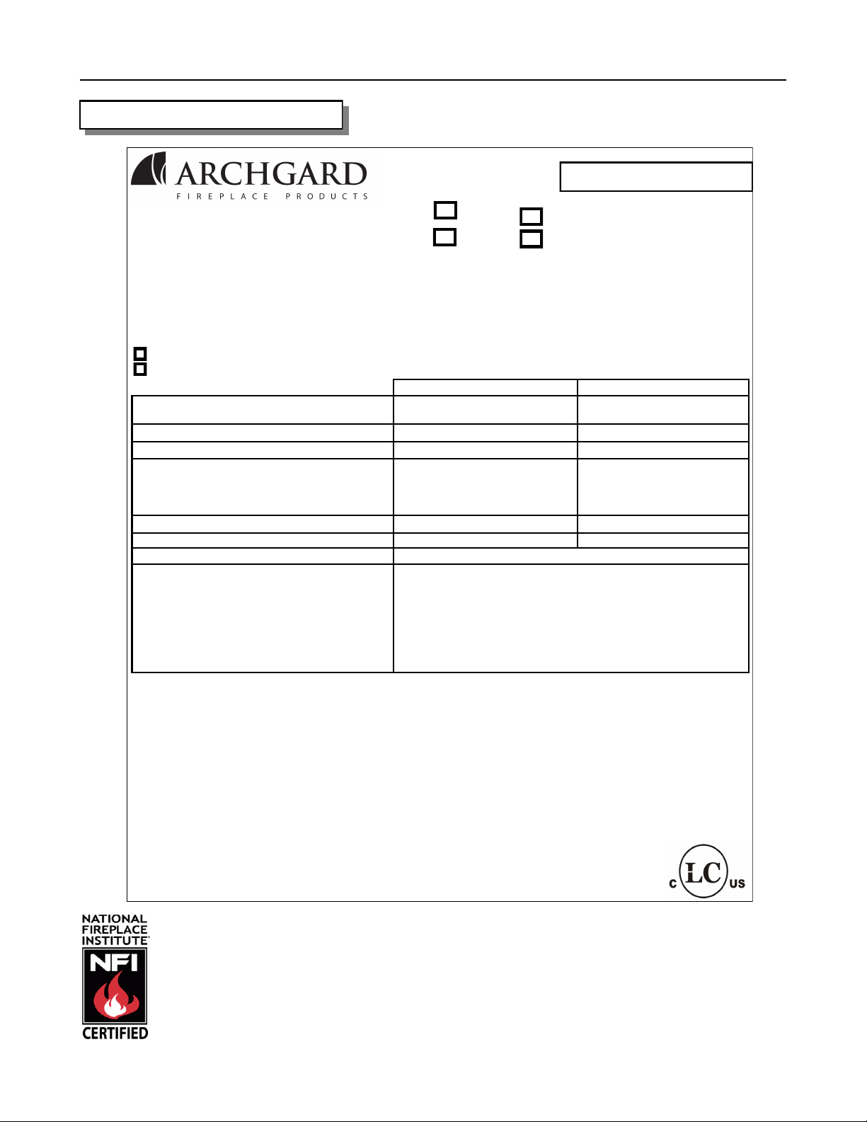
RATING PLATE
DO NOT REMOVE THIS LABEL
# de série
Serial #
C
MODEL / MODÈLE: 31 -DVIE33
L
NG / NATURAL
LP / PROPANE
LISTED VENTED GAS FIREPLACE HEATER and GAS- FIRED APPLIANCES FOR USE AT HIGH
ALTITUDES. RADIATEUR VENTILE, CIRCULATEUR DU TYPE VENTILATEUR. Tested to / Testée selon les
normes : ANSI Z21.88-2009 / CSA 2.33-2009 and CAN/CGA-2.17-M91 This vented gas fireplace heater is not for
use with air filters. Certified for use in both CANADA and USA. / Certifié pour utilisation dans le Canada et les
ÉTATS-UNIS.
VENTED GAS FIREPLACE HEATER-NOT FOR USE WITH SOLID FUEL.
SIT 885
SKYTECH 4044
Input rating / Entrée assignée
Manifold pressure / Pression d’admission 3.5 in. W.C. (0.9 kPa) 10.0 in. W.C. (2.5 kPa)
Orifice size / Dimension de l’orifice #33 DMS (2.87 mm dia.) #51 DMS (1.73 mm dia.)
Minimum supply pressure for purpose of input
adjustment / Pression minimale d’alimentation
pour le but d'ajustement de contribution
22,000 - 33,000 BTU/hr
5.0 in. W.C. (1.2 kPa) 11.0 in. W.C. (2.8 kPa)
NG LPG
(6.1 - 9.6 kW)
LC
NE PAS ENLEVER CETTE ÉTIQUETTE
24,000 - 31,000 BTU/hr
(6.9 - 9.0 kW)
Burner Primary Air Setting 1/4” (6 mm) Open 100% Open
Altitude / Elevation 0 - 4500 ft (0 - 1372 m) 0 - 4500 ft (0 - 1372 m)
Electrical rating / Tension électrique 120 VAC, 60 Hz less than 2 A. / 120 V, 60 Hz Moins que 2 A.
Keep burner and control compartment clean.
See Instructions accompanying the heater.
Maintenir propres le brûleur et le compartiment
de commande. Voir les instructions relatives à
l’installation et au fonctionnement qui accom-
pagnent le radiateur.
Optional fuel conversion kit : See Manual
This appliance must be installed in accordance with local codes, if any; if none, follow the National Fuel Gas Code, ANSI Z223.1/NFPA 54,
or Natural Gas and Propane Installation Codes, CSA B149,1. Electrical connections and grounding must be in accordance with local
codes, if any; if none, follow the current CAN/CSA C22.1 in Canada and ANSI/NFPA 70 in the US. This appliance is certified for installation
in a bedroom or a bed sitting room. This appliance is only for use with the gas indicated on the rating plate and may be installed in an
aftermarket, permanently located, manufactured (mobile) home where not prohibited by local codes. See owner’s manual for details. This
appliance is not convertible with other gases, unless a certified kit is used.
FOR USE WITH GLASS DOORS CERTIFIED WITH THIS APPLIANCE ONLY.
Il faut que cet appareil soit installé selon les codes locaux, s’il y en a; sinon, suivre le CAN/CGA -B149 actuel au Canada et ANSI Z223.1
aux É.-U. Il faut que le raccordement électrique et la mise à la masse soient en conformité avec les codes locaux, s’il y en a; sinon, suivre
le CAN/CSA C22.1 actuel au Canada et ANSI/NFPA 70 aux É.-U. Cet appareil est certifié pour l’installation dans une chambre à coucher
ou une pièce qui sert de chambre.
Made in Canada by / Fabrique au Canada par:
Minimum clearances to Combustibles / Distances:
Minimales entre l’appareil et les combustibles:
Sides from glass door frame/ Côtes: 8 ” (203 mm)
Mantle / Manteau: max 12” (305 mm) at min 39” (991 mm) from
bottom of appliance / du pied de l’appareil
See Owner’s Manual for additional clearances
Archgard Industries Ltd.
7116 Beatty Dr., Mission, B.C.
August 2013 303-6031-1
We recommend that our gas hearth products be installed and serviced by
professionals who are certified in the U.S. by the National Fireplace Institute®
(NFI) as NFI Gas Specialists.
Page 8
31-DVIE33 8
CONTROL PANEL LOCATIONS
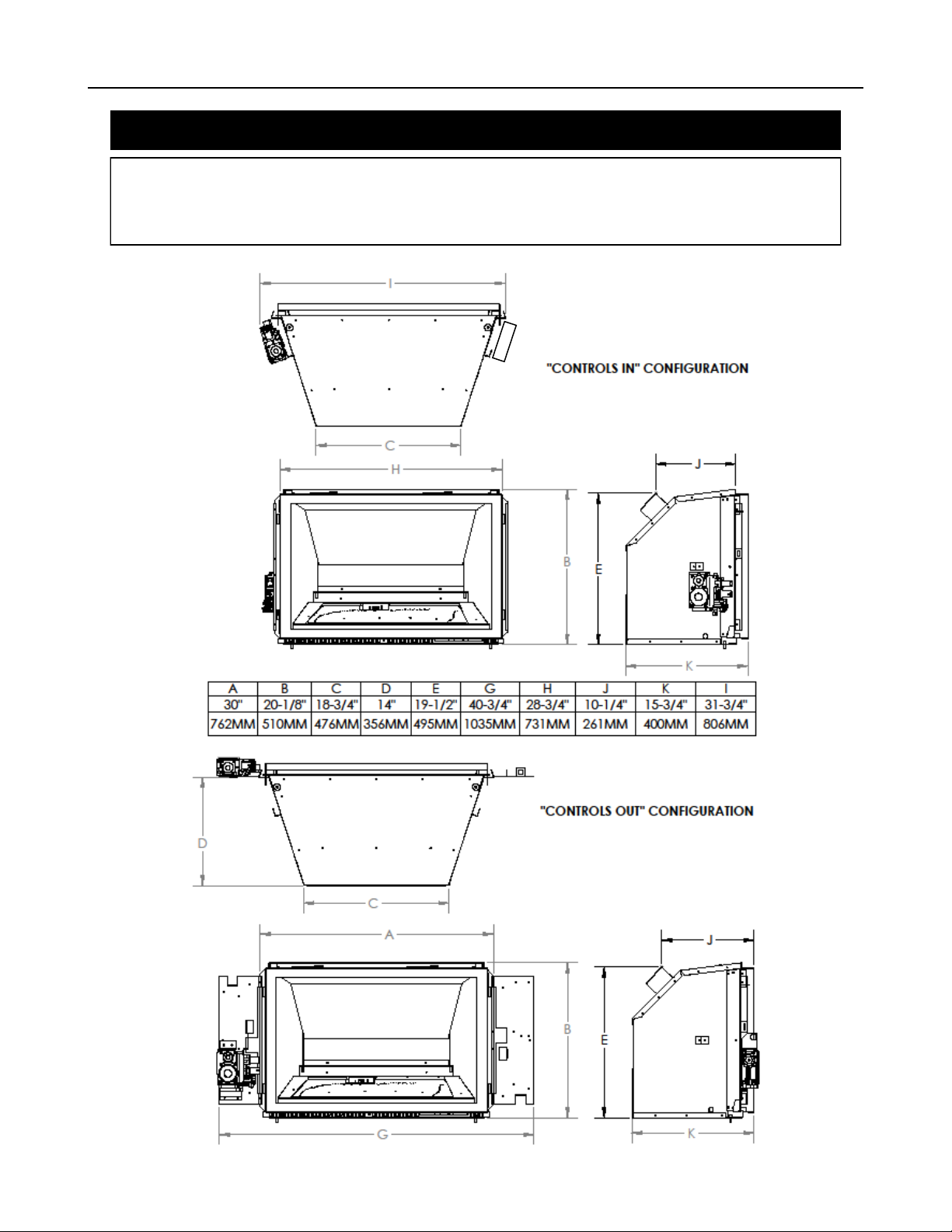
The control panels can be mounted in the following different ways. They are shipped in the “Controls In” configuration. They
can be moved to the “Controls Out” configuration by removing the two mounting screw on each side and swinging the panels
out and replacing the screws. They can also be disconnected and placed remotely within the limits of the gas connections and
electrical wiring making sure to place them away from any heat source over 150 degrees Fahrenheit or 65 degrees Celsius
Page 9
31-DVIE33 9
MINIMUM FIREPLACE DIMENSIONS
Min flue size required 4” (102) x 7” (178)
SIDE
VIEW
J
DIMENSIONS
“Controls Out”
J 20-1/4” (514 mm) 20-1/4” (514 mm)
DIMENSIONS
“Controls In”
TOP VIEW
K
L
M
TOP VIEW
CONTROLS OUT
K 14” (356 mm) 15 1/2” (394 mm)
L 19” (483 mm) 19” (483 mm)
M 30” (762 mm) 33 1/2” (851 mm)
TOP VIEW
CONTROLS IN
WARNING: Failure to position the parts in accordance with these diagrams or failure to use only parts
specifically approved with this appliance may result in property damage or personal injury.
The installer must mechanically attach the marking supplied with the gas fireplace insert to the inside of the firebox of
the fireplace into which the gas fireplace insert is installed.
Cutting of any sheet-metal parts of the fireplace, in which the gas fireplace insert is to be installed, is prohibited.
If the factory-built fireplace has no gas access hole (s) provided, an access hole of 1 1/2” (38.1 mm) or less may be
drilled through the lower sides or bottom of the firebox in a proper workmanship-like manner. This access hole must
be plugged with non-combustible insulation after the gas supply line has been installed.
The fireplace flue damper can be fully blocked open or removed for installation of the gas fireplace insert.
The fireplace and fireplace chimney must be clean and in good working order and constructed of non-combustible
materials. The chimney cleanouts must fit properly.
Refractory, glass doors, screen rails, screen mesh and log grates can be removed from the fireplace before installing
the gas fireplace insert.
Smoke shelves and baffles may be removed if attached by mechanical fasteners. Trim panels must not seal ventilation openings in the fireplace.
Page 10
31-DVIE33 10
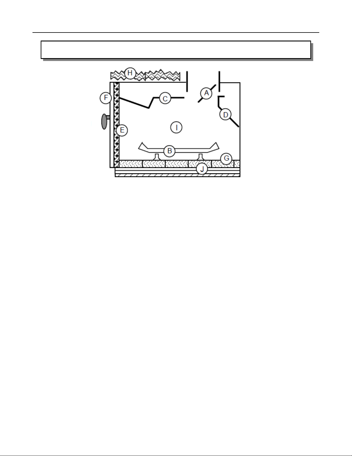
Factory –Built (metal) Wood-Burning Fireplace Requirements
Any parts that are removed must be saved and re-installed if the insert is ever removed.
The damper (A) and grate (B) must be removed
The smoke shelf (C), internal baffles (D), screen ( E), masonry lining or refractory (G and I), and
metal or glass doors (F) may be removed.
The fireplace must be permanently marked to indicate that it has been altered and is no longer
suitable for burning any fuel unless the removed parts are reinstalled. Cutting out of any metal
parts is prohibited, except the metal floor (J) as specified.
The metal floor of the firebox may be removed only if the following is
strictly adhered to.
The metal floor (J) may be removed to allow additional room for installation of the insert. If the floor is removed the insert must be placed directly on the metal base of the
metal fireplace. Under no circumstance can it be placed directly on a combustible
material.
Any hearth extending out in front of the insert must not have any portion above 7” be-
low the bottom of the unit made from combustible materials. This includes any type of
framing underneath a non-combustible material such as tile, marble or stone. Any ma-
terial below 7” can be combustible.
Page 11
31-DVIE33 11
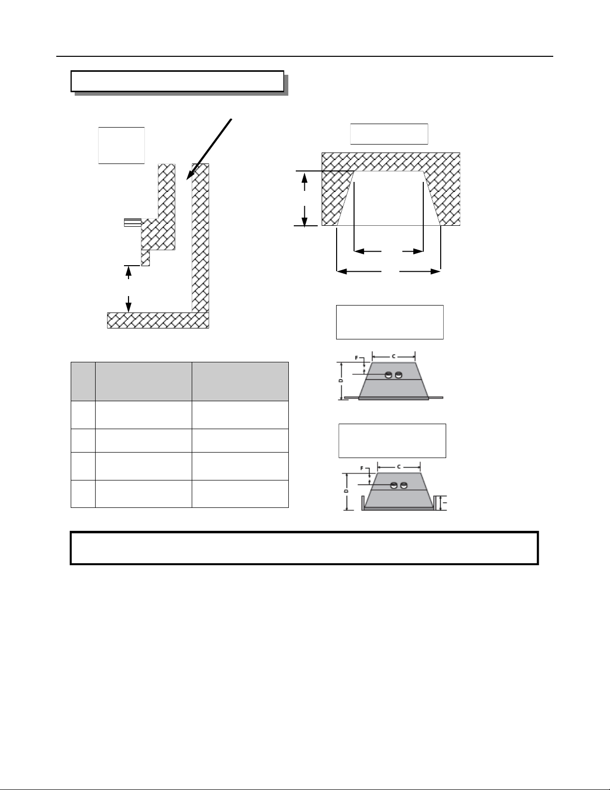
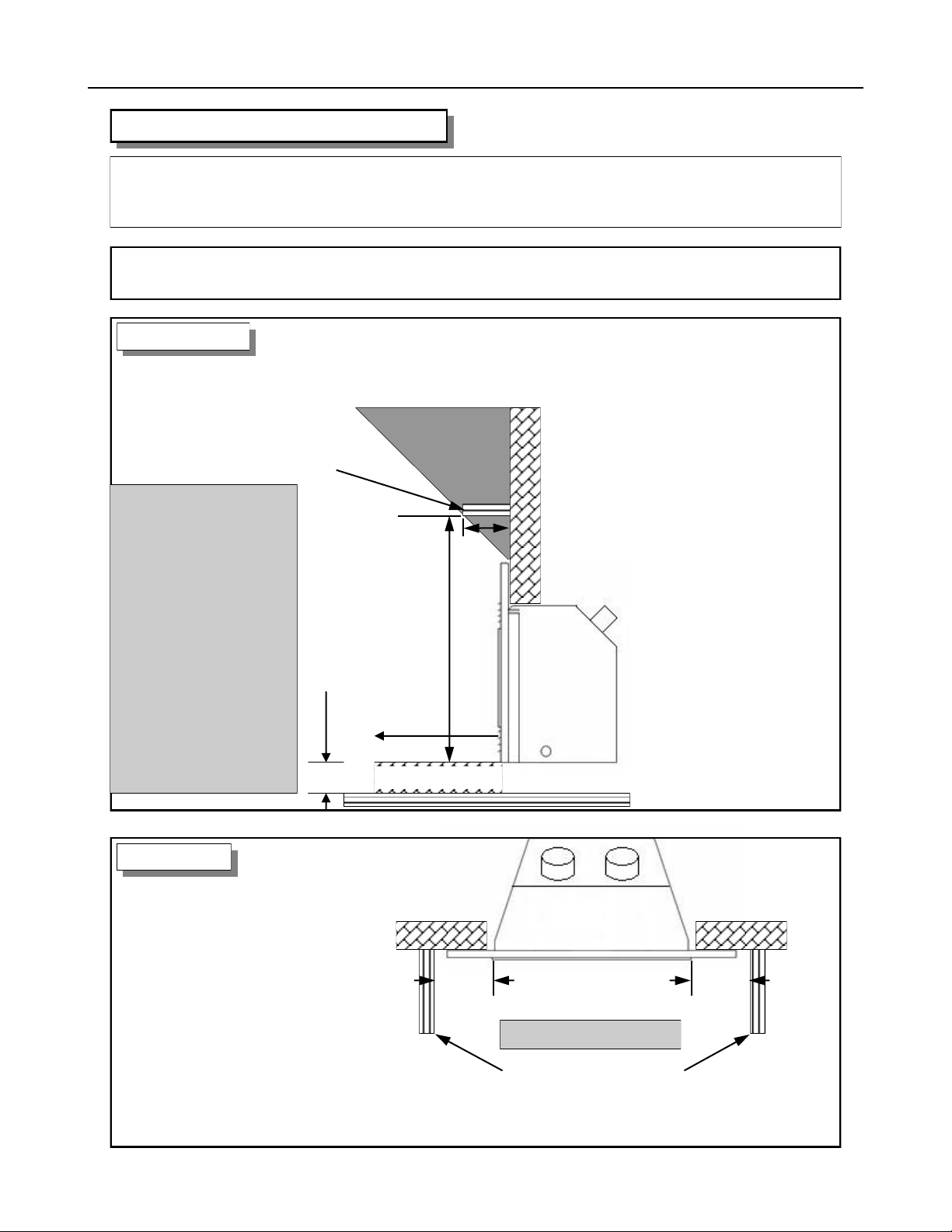
CLEARANCES TO COMBUSTIBLES
WARNING: Failure to position the parts in accordance with these diagrams or failure to use
only parts specifically approved with this appliance may result in property damage or personal
injury or loss of life.
CAUTION: This appliance is designed for use in any masonry or factory-built, wood-burning
fireplace. It cannot be enclosed by combustible material and used as a built-in gas fireplace.
SIDE VIEW
12” (305mm)
Note:
If existing wood fireplace hearth protection
is removed it must be
replaced by a noncombustible hearth
protection 7” thick,
extending a minimum
of 16” (406 mm) from
the front of the fireplace insert or have a
minimum 7” (178 mm)
clearance below the
level of the bottom of
the insert.
Minimum Height
From Bottom of
Appliance: 38”
(966 mm) with a
12”(305 mm) mantel.
Minimum clearance
to combustibles
framing
16”(406mm)
7”(178mm)
Non– Combustible Zone
Combustible mantle allowed in
shaded area. Mantle extension
maybe increased 1” (25.4 mm) for
each additional 1” (25.4 mm)
increase in clearance height.
Example: If using a 5” (127 mm)
reduce minimum height to
31” (788 mm).
If using a 4” (102 mm) reduce
minimum height to 30” (762 mm)
TOP VIEW
Minimum 8” (204 mm)
clearance is required from the
glass door frame to a sidewall
or mantle support.
8”
(204 mm)
8”
(204 mm)
Clearances to Door Frame
Sidewalls or Mantle Supports
Page 12

31-DVIE33 12
GAS CONNECTIONS
Before connecting the appliance to the gas supply line, double check that the appliance you have
purchased is designed for the gas type you are using. The gas type markings are located on the
certification label and also on the appliance’s gas valve.
Adequate clearance for proper installation and checking of the gas connections must be provided. All
gas connections must be checked for gas leaks.
Have your gas supplier or a qualified gas fitter run a gas supply line into the fireplace. The line must
be properly sized and fitted according to the installation codes. Immediately upstream of the supply
connection, the fitter shall provide an accessible manual shut-off valve. When connecting the supply
line to the gas valve, the installer shall brace the gas valve to ensure that the gas valve is not moved
from its bracket. If the valve is not braced when the supply line is connected, the valve may be
moved and cause a “break” in the main burner supply line. Such damage is not covered by the
manufacturer’s warranty.
CAUTION: The appliance and its individual shutoff valve must be disconnected from the gas supply
piping system during any pressure-testing of that system at test pressures in excess of 1/2 psig (3.5
kPa). The appliance must be isolated from the gas supply piping system by closing its individual
manual shutoff valve during any pressure-testing of the gas supply piping system at test pressures
equal to or less than 1/2 psig (3.5 kPa). Failure to do so will damage the appliance’s gas valve. Such
damage is not covered by the manufacturer’s warranty.
Natural Gas Pressure Settings:
The inlet supply or line pressure must be a minimum of 4.5” W.C. (1.2 kPa) and a maximum of 14”
W.C. (3.5 kPa). The orifice is a #33 DMS (2.87) drill size.
ELEVATION INPUT RATING
0-4500 ft (0-1372 M) 33,000 BTU/hr (9.6 kW)
4500 ft (1372 M) and above. 33,000 BTU/hr (9.6 kW) less 4% per 1000 ft. (305 M)
Please contact your local distributor for the appropriate orifice size you require.
Propane Pressure Settings:
The inlet supply or line pressure must be a minimum of 11” W.C. (2.8 kPa) and a maximum of 14”
W.C. (3.5 kPa). The orifice is a #51 DMS (1.73 mm) drill size.
ELEVATION INPUT RATING
0-4500 ft. (0-1372 M) 31,000 BTU/hr (9.02 kW)
4500 ft. (1372 M) and above. 31,000 BTU/hr (9.02 kW) less 4% per 1000 ft. (305 M)
Please contact your local distributor for the appropriate orifice size you require.
NOTE: THE INPUT RATING SHOULD ALWAYS BE CHECKED WHEN FIRST RUNNING THIS
APPLIANCE. To do this, reduce the background flow rate, time the meter, light the fireplace and
take another reading after 15 minutes of operation. Check with your gas supplier for the gas BTU
content at your elevation. Input is the rate of flow multiplied by the heating value of the gas (cubic
feet/hour x BTU per cubic feet). Adjust the manifold pressure so that the unit does not operate above
the rated input.
Page 13
31-DVIE33 13
CONVERSION KIT INSTRUCTIONS
IMPORTANT: This fireplace is Natural gas ready. If converting to LP gas, follow instructions below
WARNING: This conversion kit shall be installed by a qualified service agency in accordance with the manufacturers
instructions and all applicable codes and requirements of the authority having jurisdiction. If the information in these
instructions is not followed exactly, a fire, explosion or productions of carbon monoxide may result, causing property damage, personal injury or loss of life. The qualified service agency is responsible for proper installation of this kit. The installation is not proper and complete until operation of the converted appliance is checked as specified in the instructions
supplied with the kit. Refer to appliance owner’s manual or product data plate for proper inlet and manifold pressure
adjustments and orifice sizing.
IMPORTANT: For high altitude installations above 4500 ft (1372 meters), consult local gas distributor or the authority
having jurisdiction for proper de-rating methods.
KIT NUMBERS: 31--CKELP for LP gas and 31-CKENG for Natural Gas
KIT INCLUDES:
1- Gas conversion label (303-0128)
1- Burner orifice (301-0068) (#51 DMS for LPG) (#33 DMS for NG)
1- Instruction Sheet
1- SIT 885 Valve conversion kit c/w instructions & gas type label (0.907.012 LPG)
WARNING: SHUT OFF GAS SUPPLY AND ELECTRICAL POWER TO FIREPLACE
SHUT OFF GAS SUPPLY BEFORE DISCONNECTING ELECTRICAL POWER
PREPARE THE FIREPLACE
Remove the surround, glass frame assembly, logs and brick (if applicable).
Remove the burner air tray by removing the two screws at the back wall and lifting the tray up and out.
Remove burner by removing the screw on each side of the burner and sliding the burner to the right and then tilt up.
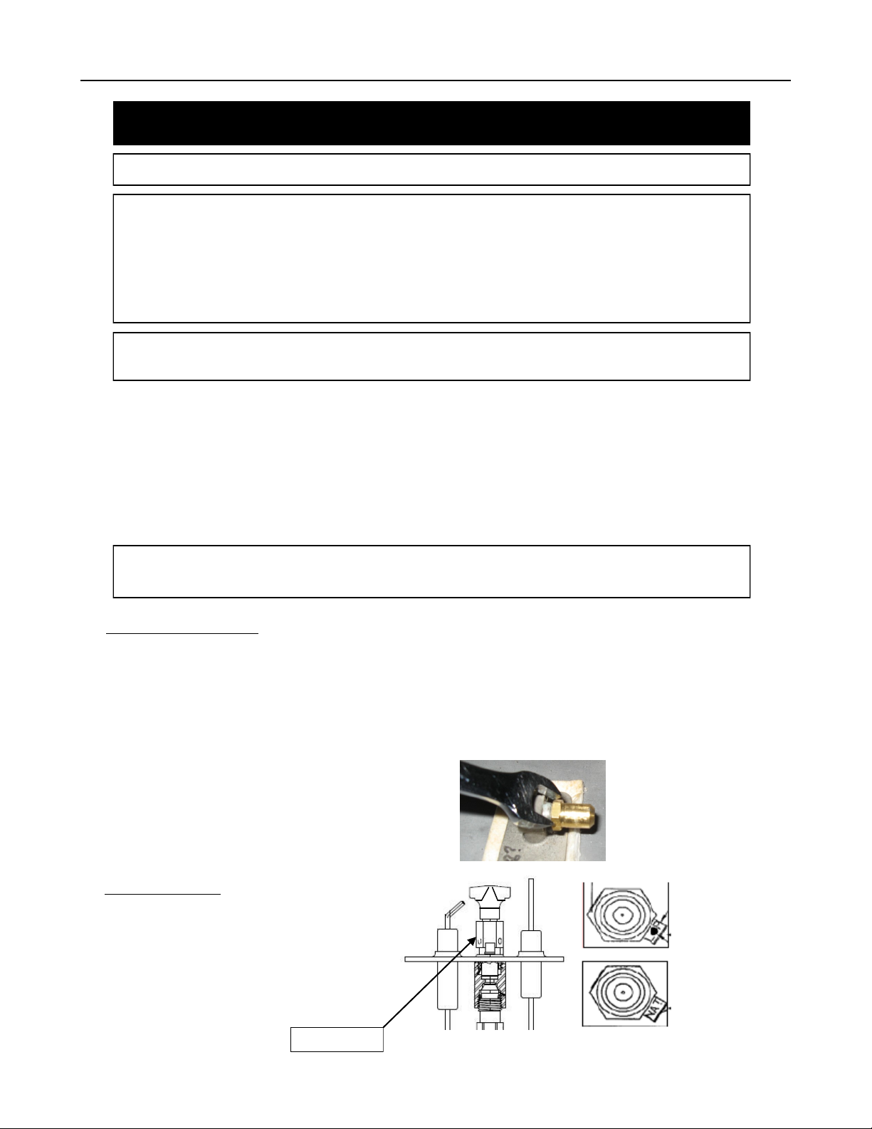
Remove the burner orifice using a 1/2” wrench. Replace with the
orifice supplied with the conversion kit. Use a small amount of
pipe sealant.
PILOT CONVERSION
Using a 7/16” wrench and loosen the pilot hood 1/4
turn. Slide the tab at the bottom of the orifice hood all
the way so the red side (propane) with the hole in it is
showing. Tighten the pilot hood back up so that it is
lined up with the two probes on both sides of the pilot
assembly.
Figure 22
LP has hole
and red dot
Natural Gas
Wrench here
Page 14
31-DVIE33 14
CONVERSION KIT INSTRUCTIONS CONT.
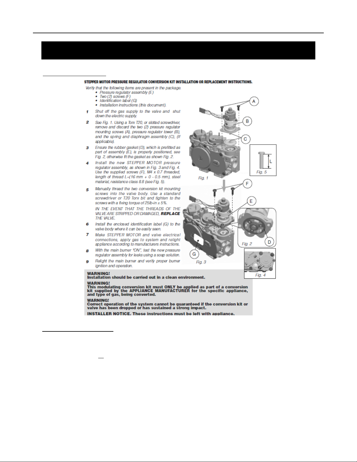
CONVERT THE GAS VALVE
COMPLETE THE CONVERSION
Turn on the gas and electrical supplies.
Turn on the fireplace so the burner is on
Check for leaks at all connections.
Test inlet and outlet pressure. Visually check pilot flame. Flame should envelope top of the flame sensor and extend
forward onto the burner. To adjust pilot turn the pilot adjustment screw on the control valve clockwise to
decrease or counter clockwise to increase pilot flame.
Turn fireplace off
Affix gas type label to the rating plate label. (Bottom right side, under the door frame of insert on pull chain)
Complete the conversion label and affix to valve assembly plate.
Re-install the burner, brick, logs, embers and door. (per the instructions starting on pg. 19)
Page 15
31-DVIE33 15
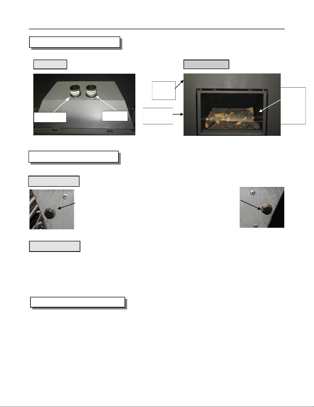
APPLIANCE DESCRIPTION
TOP VIEW
Exhaust
LEVELING THE 31-DVIE33
Front Level
Located slightly in from the front edge of the fireplace is the new leveling feature. Leveling bolts can be installed to enable you to raise the
front of the firebox if necessary. If you need higher adjustment you only
need to change to a longer bolt. If no rise is required simply leave
empty.
Intake
On/Off
Rocker
Surround
Faceplate
FRONT VIEW
Ceramic
Glass w/
standard
black
door
Rear Level
Before placing the appliance into the fireplace, check the hearth of the fireplace to see if it is level
with the front of the fireplace. If it is not, measure the depth of the hearth. Loosen the three screws of
the leveling “L” bracket at the back of the appliance. Lower it to the measurement obtained and
tighten the screws.
ELECTRICAL CONNECTIONS
The 31-DVIE33 comes complete with an adjustable 6 speed fan wired directly to the main control
module for your protection against shock hazard.
Do not cut or remove the grounding prong from this plug.
NOTE: This appliance, when installed, must be electrically grounded in accordance with local codes
or, in the absence of local codes, with the National Electrical Code, ANSI / NFPA 70, or the
Canadian Electrical code, CSA C22.1.
Page 16

31-DVIE33 16
VENTING INSTRUCTIONS
WARNING: Operation of this heater when not connected to a properly installed and maintained venting
system can result in carbon monoxide (CO) poisoning and possible death. The appliance must not be
connected to a chimney flue serving a separate solid fuel burning appliance.
C A U T I O N
Only 3” (76mm) double wall aluminum flex liner and approved vent terminals are to be used for this appliance.
APPROVED TERMINATIONS
Manufacturer Vertical Termination Termination Adapter
Archgard
Dura Vent
ICC/Excel
Ameri-vent
999-INS-TK N/A
980 - Co-Axial Cap (requires adapter)
991 - Co-Axial High Wind (requires adapter)
IVT - Co-Linear
VT - Co-Axial (requires adapter)
SVT- Co-Axial (requires adapter)
DVC - Co-Axial Cap (requires adapter) DCAT (Co-Axial to Co-Linear)
923GK (Co-Axial to Co-Linear)
N/A
CTA or CAA (Co-Axial to Co-Linear)
CTA or CAA (Co-Axial to Co-Linear)
A T T E N T I O N
NO OTHER VENTING SYSTEM OR COMPONENTS MAY BE USED. Follow manufacturer instructions for
installation of termination.
This appliance is designed for dual 3” (76 mm) double wall aluminum flex liner, running the entire length of the
chimney.
The flue length must be a minimum of 10’ (3.05 M) and a maximum of 40’ (12.2 M)
The exhaust vent restrictor provided with this appliance must only be used by installing it onto the
front of the baffle when the vent height is over 18’ (5.5 M) if required.
The minimum (chimney) flue size is 4” x 7” (102 mm X 178 mm).
Masonry chimneys may take various contours which the flexible liner will accommodate, however, keep the
flexible liner as straight as possible, avoiding unnecessary bending but at all times keep a minimum of 3” (76
mm) inside bend radius.
The Air Intake Flex Liner must be connected to the inlet air
collars of the termination cap and the appliance.
The Exhaust Flex Liner must be connected to the exhaust
collars of the termination cap and the appliance.
The Air intake and Exhaust connections are marked on
the gas appliance. See picture.
DO NOT REVERSE THESE CONNECTIONS
C A U T I O N
To ensure that the venting is not accidentally obstructed or punctured,
the damper of the host fireplace must be permanently disabled.
Either complete removal of the damper, or welding it in its “open” posi-
tion. Temporarily disabling the damper is not permissable.
The 31-DVIE33C showing the Fresh Air Intake and
Exhaust locations. These connections are labeled.
TOP VIEW
Exhaust Fresh Air
The 31-DVIE33C requires (2) flexible flue liners:
INLET Collar - 3” (76 mm) diameter
OUTLET Collar - 3” (76 mm) diameter
Page 17

31-DVIE33 17
VENTING INSTRUCTIONS 999-INS-TK
Instructions for use with Archgard vertical termination cap. Part # 999-INS-TK
Install the termination cap being sure to provide sufficient space (around and on top) so as not to impede the flow of air, both
into and out of the cap. This cap is only to be used for non combustible installations. Do not recess into the top of the chi mney.
1. Mark each end of one liner with “Air Intake”.
2. Mark each end of the second liner with “Exhaust”.
3. Pull the liner through the chimney.
4. Install the flashing.
5. Seal and attach the liner marked “Air Intake” to the vent terminal pipe marked “Air Intake” with the collar clamp provided.
6. Seal and attach the liner marked “Exhaust” to the vent terminal pipe marked “Exhaust” with the collar clamp provided.
7. Seal and attach the end of the flex marked “Air Intake” to the collar marked “Air Intake” on the appliance with the collar clamp
provided with the unit.
8. Install exhaust vent restrictors provided with the unit if required. Seal and attach the end of the flex marked “Exhaust” to
the collar marked “Exhaust” on the appliance.
9. Caulk all joints using a high temperature sealant such as milpac. DO NOT USE SILICONE SEALANTS. Use of silicon sealants
voids the warranty of the pilot assembly.
NOTE: The vertical termination cap must be sealed to the liner with suitable high temperature sealant, such as milpac and with the hose
clamps fasteners provided. DO NOT USE SILICONE SEALANTS (Use of silicon sealants voids the warranty of the pilot assem-
bly) The liners must form a complete connection from the appliance flue collars to the vertical termination cap.
Vertical Termination cap
Part # 999-INS-TK
Exhaust
Collar
Min. vent height 10’(2.54 M)
Max. vent height 40’ (12.2 M)
Vent Restrictor may be
needed when operating
with a vent over 18’ (5.5m)
See next page
Air Intake
Collar
3” (76 mm) Flex Liner
Fresh Air Intake
N O T E
Seal and secure liners on unit
and at roof termination
Front view of
DV Insert
The minimum flue (chimney) size required to run the two 3” (76 mm) is 4” x7” (100 mm X 178 mm)
Page 18

31-DVIE33 18
VENT RESTRICTOR INSTALLATION
When the vent is over 18’(5.5m) a vent restrictor may be required. The installation of the restrictor will equalize the vent
stack action that can cause problems with a proper fire set-up.
The vent restrictor is supplied loose in the manual bag. When required, it installs onto the upper baffle in the center portion.
The baffle air openings are located in the top of the firebox just inside the front frame of the fireplace. There are holes already in the standoffs that will line up with the holes in the restrictor.
Firebox baffle w/out
restrictor.
All three air channels
Upper Baffle
air channels
SURROUND INSTALLATION
Surround options available are dependent upon the control panel configuration. (See Control Panel Locations
regarding configuration.) Shallow surround options are
not available on a unit with ‘Controls Out’ configuration.
Make sure the gas and electrical lines are properly connected to the appliance. Slide the unit into the fireplace
and slide the excess flue liner material back onto the
chimney. Before the appliance is fully recessed into the
fireplace, attach the surround onto the appliance.
Attach the surround to the appliance at the locations
shown by lining up the tabs on the surround with the
slots on the unit. Make sure the surround drops down
and fully engages. Then finish with the wiring connection
to the on/off switch on the side of the trim. Now fully
“seat” the unit into its final position.
in the baffle are open
Restrictor installed
in upper baffle.
Center air channel
is closed off with
restrictor
Surround Mounting slots
Upper Baffle
Surround Mounting
tabs
Main On/Off switch must be connected to the surround switch and in the “on” position for the remote to operate the fireplace
Page 19

31-DVIE33 19
LOG PLACEMENT
The Archgard pan burner bed and fiber logs are designed to give a realistic fire package, and
created to look the same as the day they were originally installed. Care must be given when
first installing the logs, and if removed for servicing, as they can be damaged or broken if not
handled properly.
After opening the log set package, inspect the logs to ensure that no damage has occurred
inside the package. Please report any damage immediately to your Authorized Archgard
Dealer.
Gas and vent connection must be made before installing the embers and logs on the pan
burner.
NOTE: Improper placement of logs and embers may cause soot accumulation on the internal
parts and glass. This is not covered under warranty. Do not use broken or damaged logs.
WARNING:
Failure to position the parts in accordance with these diagrams or failure to use only parts
specifically approved with this appliance may result in property damage or personal injury.
Locate the embers and logs and place them on their prospective locations. Refer to the pictured
instructions on the following pages that will show how to place all seven (7) logs. Pins and holes
must be aligned with logs and burner.
IMPORTANT: Embers should be placed so as not to completely block burner ports. Separate
the material and spread around the pan.
Locator Pins
BURNER AIR TRAY
LOCATOR PINS
NOTE: Installing the fiber logs in any other position other than shown will result in flame
impingement causing sooting of the logs, brick liner and ceramic glass viewing area.
Page 20

31-DVIE33 20
Logs
LOG 1
LOG 5
LOG 7
LOG 4
LOG 6 LOG 3
LOG 2
Item # Item Description Qty Unit
310-634720-1 Log 1 (Left Rear) 1 EA
310-634720-2 Log 2 (Right Mid) 1 EA
310-634720-3 Log 3 (Left Mid) 1 EA
310-634720-4 Log 4 (Right) 1 EA
310-634720-5 Log 5 (Left Top) 1 EA
310-634720-6 Log 6 (Front Crossover) 1 EA
310-634720-7 Log 7 (Right Rear 1 EA
310-0020 Black Embers (2 cup bag) 1 EA
Page 21

31-DVIE33 21
LOG PLACEMENT... Continued
Step 1. Locate Log 1 and align the holes in the bottom line up with the two locater pins.
Push the top of the log up so it is against the back shelf. Push down firmly onto locater pins.
LOG 1
Step 2. Locate Log 7 and place over the two pins and all the way back against the back
shelf and to the left so it is almost touching Log 1. Force the log down onto the locater pins.
NOTE: There are no holes in Log 7 must use gentle force.
LOG 7
Page 22

31-DVIE33 22
LOG PLACEMENT... Continued
Step 3. Locate Log 3 and align the two holes in the log with the two locater pins on the left
of the burner. Push down onto locator pins as shown.
LOG 3
Step 4. Locate Log 2 and align the two holes in the log with the two locater pins on the right
side of the burner. Push down onto locator pins as shown.
LOG 2
Page 23

31-DVIE33 23
LOG PLACEMENT... Continued
Step 5. Locate Log 5 and align the hole in the bottom with the pin in log 3. Place the other
end of the log in the saddle of log 1.
LOG 5
Step 6. Locate Log 6 and align the hole in the bottom with the locater pin in log 3. Place the
other end of the log on the burner and pulled forward against log 2.
LOG 6
Page 24

31-DVIE33 24
Step 7. Locate Log 4 and align the hole in the bottom with the pin on the burner surround
tray. Place the other end onto log 2 as shown.
LOG 4
Step 8. Place black embers around logs as shown , do not block the holes in the burner.
Maintain a 1/4” clearance from the Burner Cover with embers
Burner Air Tray
Black Embers
Page 25

31-DVIE33 25
GLASS DOOR REMOVAL AND REPLACEMENT
WARNING: Do not operate appliance with the glass front cracked or broken. Replacement of
the glass should be done by a licensed or qualified service person.
CAUTION: Do not attempt to remove the glass door when the appliance is hot.
1. Just above the door frame reach in and pull the two finger rings forward (see figure 1).
2. Pull and lift the finger rings to detach from the door frame (see figure 2).
3. Pull the door forward until the bottom catches release.
4. Lift door up and away.
5. To replace the door line up the two bottom catches with the notches on the fireplace.
While pushing evenly on the bottom of the door lift up on the top of the door until it
engages.
6. Push down on the top of the door to ensure the door is seated all the way down on the
catches.
7. Pull the finger rings out and down to engage in the slots on the top of the door frame.
8. Push the finger rings back in.
FIGURE 1 FIGURE 2
IF YOUR GLASS BREAKS
In the event your glass cracks or breaks, Archgard recommends that a new door assembly be ordered to
replace the original door.
Remove door as per the instructions above.
Replace with new door assembly.
NOTE: the NEW door will emit some odor when the appliance is re-lit and the odor will dissipate after the
gasket material within the door has cured.
Warning : Do not use substitute glazing materials
Page 26

31-DVIE33 26
FINAL INSTALLATION CHECK
Each Archgard Gas Fireplace is checked and tested at the factory prior to being packaged and
shipped to our dealers and finally installed in your home. Archgard recommends that before
leaving this unit with the customer, the installer must ensure that the appliance is firing
correctly and that the electrical system is in working order. This will include:
1. Perform leak tests of supply line, gas control valve, supply line from gas control valve and
pilot assembly.
2. Clocking the appliance to ensure the correct firing rate (see page 6 of this manual).
3. If required, adjusting the primary air to burner to ensure that the flame does not carbon or
soot.
4. Check for proper operation including correct drafting.
5. The fireplace should be turned ON to ensure that the fan is working correctly. After the system has been checked and confirmed that the fan is in working order, refer to the instructions for FIRST FIRE located in this manual.
As a reminder, a TAG is attached to all of our gas fireplaces. This TAG is located at the gas
control valve. See below.
ARCHGARD INDUSTRIES LTD.
*** INSTALLER ***
IMPORTANT NOTICE
ALL GAS AND ELECTRICAL CONNECTIONS
** MUST ** BE CHECKED AND TESTED AT
TIME OF INSTALLATION.
Any alteration to the product that causes carbon or soot deposits that results in any
damage or requires cleaning is not the responsibility of the manufacturer.
INITIAL OPERATION
1. Check that the appliance is properly vented and connected to the gas supply.
2. Check that the logs and branches are properly placed.
3. Check that all external parts, such as door and faceplate are properly attached and
fastened.
4. Do not operate this appliance with broken, cracked glass doors or without the door (s) in its
correct (and latched) position. Do not abuse the glass by either striking or slamming shut.
5. Check that there are no fingerprints left on glass panels, as high temperature can bake
these prints on permanently.
Page 27

31-DVIE33 27
FIRST FIRE
When operated for the first few times, the appliance will emit some odor and fumes. This is due
to the heat from the appliance evaporating the oils and solvents used in fabricating the
appliance. Close off the room to the rest of the house and open all windows. Keep the room
well ventilated, as smoke alarm may sound. Run the appliance for at least 6 hours at maximum
setting with blower set to “OFF” to allow paint to cure (after the installer has checked to ensure
the fan is operational). Smoke and fumes caused by the curing process may cause discomfort
to some individuals.
LIGHTING INSTRUCTIONS - CAUTION
WARNING : If you do not follow these instructions exactly, a fire or explosion may
result causing property damage, personal injury or loss of life. Do not
operate the appliance with the glass front removed, cracked or broken.
Replacement of broken glass should be done by a licensed or qualified
service person.
WARNING : This appliance needs fresh air for safe operation and must be installed
so there are provisions for adequate combustion and ventilation air.
WARNING : This appliance needs fresh air for safe operation and must be installed
Do not store or use gasoline or other flammable vapors and liquids in the vicinity of this or any
other appliance.
WHAT TO DO IF YOU SMELL GAS:
Do not try to light any appliance.
Do not touch any electrical switch; do not use any phone in your building.
Immediately call your gas supplier from a neighbor’s phone. Follow the gas supplier’s
instructions.
If you cannot reach your gas supplier, call the fire department.
Installation and service must be performed by a qualified installer, service agency or the gas
supplier.
1. BEFORE LIGHTING, smell all around the appliance area for gas. Be sure to smell next
to the floor, because some gasses are heavier than air and will settle on the floor.
2. IF YOU SMELL GAS, follow the instructions as listed directly above or as shown on the
front cover of this manual.
3. Do not use this appliance if any part has been under water. Immediately call a qualified
service technician to inspect the appliance and to replace any part of the control system
and any gas control which has been under water.
4. This appliance is equipped with an ignition device which automatically lights the pilot and
main burner. The pilot and burner light automatically with the hand held remote or with
the switch on the side of the surround if it is activated.
so there are provisions for adequate combustion and ventilation air.
Page 28

31-DVIE33 28
LIGHTING INSTRUCTIONS ON RATING PLATE
Page 29

31-DVIE33 29
REMOTE CONTROL SETUP AND OPERATION
(NA on this unit)
Future option
Page 30

31-DVIE33 30
REMOTE CONTROL SETUP AND OPERATION, cont.
*
(future option)
* N/A on this unit
Page 31

31-DVIE33 31
REMOTE CONTROL SETUP AND OPERATION, cont.
Page 32

31-DVIE33 32
REMOTE CONTROL SETUP AND OPERATION, cont.
Note:
When the fireplace is started in Smart Thermostat mode, the fan will come on 5min after ignition and shut down 12min after fire is turned off
Page 33

31-DVIE33 33
REMOTE CONTROL SETUP AND OPERATION, cont.
Note:
When the fireplace is started in Smart Thermostat mode, the fan will come on 5min after ignition and
shut down 12min after fire is turned off
Page 34

31-DVIE33 34
REMOTE CONTROL SETUP AND OPERATION, cont.
In manual mode the fan will activate immediately upon burner ignition. Adjust the fan speed to
personal preference. Blower will shut off when the burner is extinguished.
The unit is shipped from the factory
with the ability for IPI/CPI selection
active.
To disable the Continuous
Pilot selection ability, cut one
of the wires (blue or white)
shown in the picture and cap
them off to prevent shorting.
Page 35

31-DVIE33 35
REMOTE CONTROL SETUP AND OPERATION, cont.
Page 36

31-DVIE33 36
MAINTENANCE
CAUTION:
Do not conduct maintenance on the appliance while it is operating or while it is still hot.
CLEANING THE APPLIANCE
The exterior painted surfaces, glass and gold trims may be cleaned with a soft, non-abrasive
cloth and water or a suitable, mild, non-abrasive cleaner.
Regularly:
Frequent cleaning of the ceramic glass is required. Archgard recommends using a good
quality “gas fireplace” glass cleaner that is available at any hearth retail location. DO NOT
CLEAN WHILE HOT.
Clean and remove any lint accumulations or debris from the combustion and convection
air passage ways.
Keep the appliance area free from combustible materials, such as paper, wood, clothing,
gasoline and flammable solids, liquids and vapors.
Visually check the height and color of the burner and pilot flames.
Every 2 to 3 months:
Remove the glass door and clean the inside of the glass with a good quality “gas
fireplace” glass cleaner. DO NOT CLEAN WHILE HOT.
Carefully remove the logs and gently brush off any loose carbon deposits. This job is best
done outside the house, wearing a dust mask.The logs are very fragile, take care not to
break them. Do not wash logs with any liquid. While the logs are removed, check that
all burner openings are not obstructed and it is recommended you use a vacuum cleaner
to clean off any dust or lint.
After cleaning, the logs and embers must be replaced as per the instructions in this
manual.
Once a year, have a qualified service technician:
Completely inspect the appliance and the venting system, if the vent pipe or seal is found
to be defective, replace and or reseal (follow the instructions found in the venting
instructions section)
Clean and remove any lint accumulations or debris in the firebox, on the burners, on the
pilot, at the primary air opening, on the convection air blower and in any combustion and
convection air passageways.
Check the safety system of the gas valve and the appliance.
WARNING: All parts removed or disturbed, including guards and grills, must be
properly replaced after maintenance. Service and repair must be
conducted by a qualified service person. If these instructions are not
followed, a fire or explosion may result, causing property damage,
personal injury or loss of life.
Page 37

31-DVIE33 37
SERVICING UNDER WARRANTY
Before servicing, read the terms and conditions of the Archgard warranty at the back of the
manual. Contact the authorized Archgard dealer where you purchased the appliance from and
provide them with details of the problem, along with the initial installation information (from the
front of this manual).
WARNING: Servicing of this appliance must be conducted by a qualified service
technician. Improper servicing, adjustment or alteration of this appliance may
cause property damage, personal injury or loss of life. All servicing should be
conducted with the appliance cold. All replacement parts must be authorized by
Archgard for suitability.
ADJUSTING PRIMARY AIR
NOTE: Figure 1 is to give an example of what a correct or incorrect flame pattern looks like. It is
not a true representation of what the 31-DVIE33 will look like in your home environment.
The air shutter can be adjusted from the front of the unit while in operation. All adjustments
should be made after 20 minutes of operation.
1. Locate the Robertson screw below the glass door and left of center.
2. Turn the screw clockwise to give more air ( less yellow flame ). Turn the screw counter
clockwise to give less air (more yellow flame).
FLAMES
The left side shows correct adjustment.
The right side shows yellow sooty
flames requiring increase in shutter
opening or cleaning of shutter area,
due to lint buildup.
FIGURE 1
Page 38

31-DVIE33 38
CHECKING INLET AND OUTLET GAS PRESSURE
1. Remove the surround.
2. The pressure test taps are located on the valve. The taps are located in the gas valve front face.
The inlet is marked ‘IN’ and the outlet is marked ‘OUT’. See Fig.1.
3. Loosen the set screw inside the tap with a screwdriver.
4. Connect a 1/4” (6 mm) rubber tube to the tap post and a manometer.
5. Verify that the readings obtained are within specs (as shown on the appliance rating plate)
6. Be sure to tighten the set screw inside the tap after you have finished taking pressure readings.
7. Check for leaks.
CHECKING AND ADJUSTING PILOT
The pilot flame should have the characteristic
as shown in the illustration to the right.
The flame should not have yellow tips but
should engulf the flame sensor and spark
electrode. It can be adjusted be turning the
screw marked “pilot” on the control valve.
Ignitor
Sensor
Page 39

31-DVIE33 39
REPLACING CONVECTION BLOWER
CAUTION: Label all wires prior to disconnection when servicing controls. Wiring errors can
cause improper and dangerous operation. Verify proper operation after servicing.
This appliance, when installed, must be electrically grounded in accordance with local codes
or, in the absence of local codes, with the National Electrical Code, ANSI/NFPA 70, or the
Canadian Electrical code, CSA C22.1.
NOTES:
Make sure the gas to the appliance has been shut off.
Ensure that the main power and breaker system is turned off before removing the fan.
Make sure the fireplace has been turned off and is cool to the touch.
Mark all wires to be removed for proper reassembly.
CAUTION: Wiring errors cause improper and dangerous operation.
The convection fan can be accessed either through the front of the insert or through the back of
the insert.
TO ACCESS FROM THE FRONT
1. Remove the glass door. Follow GLASS DOOR REMOVAL instructions within this manual.
2. Remove the log set. Follow LOG PLACEMENT instructions within this manual
3. Remove the pan burner. Follow instructions for CHANGING MAIN BURNER ORIFICE within
the conversion section of this manual.
4. Remove the access cover (section set at 45 degree angle) of the firebox by removing the 1/4
“ hex head screws and lifting out. When re-installing access cover make sure to replace the
gasket with a new ceramic gasket if required.
5. Remove the four nuts holding the fan in place.
6. Disconnect the wires.
7. Mark all wires to be removed for proper reassembly.
8. Install new fan in reverse order.
9. Reverse these steps after new fan is installed & tested.
TO ACCESS FROM THE BACK
1. Remove the surround by lifting up and forward.
2. Disconnect the gas line.
3. Disconnect the intake and exhaust liners
4. Remove the insert from the fireplace.
5. Remove 1/4” hex head screws and the cover plate at the back of the insert
6. Remove the 1/4” hex head screws holding the fan bracket.
7. Disconnect the wires.
8. Remove the 4 nuts holding the fan to the bracket.
9. Replace the fan with the new fan.
10. Reassemble in the reverse order.
Page 40

31-DVIE33 40
WIRING SCHEMATICS
Main On/Off switch must be
connected to the surround
switch and in the “on” position
for the remote to operate the
fireplace
Synchronization
button
Page 41

31-DVIE33 41
ARCHGARD
This Limited Warranty is made by ARCHGARD INDUSTRIES LTD., hereinafter referred to as “Archgard”. Archgard warrants to the
original purchaser of an Archgard gas burning fireplace (s) that the product will be free of defects in materials and workmanship under
normal use and service, for a “lifetime”.
INCLUSIONS: “LIFETIME LIMITED WARRANTY“
ARCHGARD
LIMITED WARRANTY
LIMITED WARRANTY
❖ All heat exchangers, combustion chamber, burner tubes and pans.
❖ Ceramic Fiber Logs and Ceramic Brick Panels against splitting or cracking from heat exposure.
❖ Ceramic Glass against thermal breakage.
❖ NOTE: Discoloration and some minor movement of certain parts are normal and are not a defect and therefore, not covered under war-
ranty.
The above will be covered “parts & labor” to the original purchaser for FIVE years and “parts” only thereafter from original date of purchase.
INCLUSIONS: “FIVE YEAR LIMITED WARRANTY”
❖ Five year limited warranty on the Burner System. Warranty will cover any defective burner if defect is deemed as original by the manu-
facturer.
The above will be covered “parts & labor” to the original purchaser for TWO years and “parts” only thereafter from original date of purchase.
INCLUSIONS: “ONE YEAR LIMITED WARRANTY”
❖ All 24 K gold trims and accessories against tarnishing.
❖ All trim accessories against tarnishing and paint defects.
❖ Blowers, fans and fan motors, wiring, rheostats and thermodiscs.
❖ Rocker switches, spill switches and wiring to them.
❖ Gas control valves, pilot assemblies including thermopiles, thermocouples, electrodes, and igniters.
The above will be covered “parts & labor” to the original purchaser for ONE year from date of purchase.
EXCLUSIONS:
❖ Ember material.
❖ Tempered Glass is under warranty for ONE year to the original purchaser from date of purchase.
❖ Travel time or mileage to original purchasers residence. Archgard suggests that you pre-arrange travel expenses with your Authorized
Archgard Dealer.
WHAT TO DO IN THE EVENT OF A PROBLEM:
❖ Thoroughly read your manual.
❖ If you cannot solve the problem, contact your Archgard Dealer or representative.
❖ When calling for help please have the following information:
Model of your Fireplace Serial Number Place of Purchase
Date of Purchase Problem Description
❖ NOTE: Warranty may be void if work is carried out by an unqualified person (s). Only original Archgard parts may be used. Please
consult your Archgard dealer or representative if in doubt about a replacement part (s).
OBTAINING WARRANTY SERVICE:
To obtain warranty service, the original purchaser shall return the defective part (s) to the original authorized Archgard selling dealer transportation prepaid, along with the serial number of the appliance and proof of purchase. Any defective part, in our
judgment, will be repaired or replaced at Archgard’s discretion. The dealer must obtain approval from Archgard before any
repairs are made.
WARRANTY LIMITATION:
THIS LIMITED WARRANTY IS MADE IN LIEU OF ALL OTHER WARRANTIES, EXPRESSED OR IMPLIED AS TO QUALITY,
MERCHANTABILITY OR FITNESS FOR PARTICULAR PURPOSE.
The appliance is only warranted for the use as intended by the installation and operating instruction and local building codes. The warranty
will not cover damage due to accident, misuse, abuse, alteration, improper installation or “Acts Of God”.
This limited warranty is void unless the appliance is installed by a qualified installer, in accordance with the instructions
furnished with the appliance. Some Provinces or States do not allow limitations on how long an implied warranty lasts, so the above limitation may not apply to the original purchaser. Any damage resulting from defects in this product, is limited to the
replacement of the defective part (s) and does not include incidental and consequential exposures sustained in connection with the product.
This includes facing (s), mantle (s), cabinet (s), tile (s) or any other finishes resulting from removal of any gas appliance. This warranty is
limited to residential use only and gives the consumer specific rights. These rights may vary from State to State or Province to Province.
Page 42

31-DVIE33 42
FREQUENTLY ASKED QUESTIONS
Listed below are some frequently asked questions regarding Archgard Gas Fireplaces. If you have questions that are not listed below, or are not answered in this manual, please contact your Authorized
Archgard Dealer.
Q. My glass has a condensation “fog” when the appliance is first lit.
A. Condensation is normal and will disappear in a few minutes after the glass is heated.
Q. I have a white “film” on my glass. What is the best way to clean the inside of the glass.
A. Frequent cleaning of your glass is recommended. Archgard recommends using a good quality “gas
fireplace” glass cleaner that is available at all authorized dealers. Do not use abrasive materials, and do
not clean the glass or the appliance when the unit is hot.
Q. How do I care for my plated trims.
A. Archgard recommends a cleaning with a damp cloth. DO NOT use chemical cleaners as they may
harm the finish, and void your warranty. NOTE: If the top louvers, or top overlay starts to discolor, check
the door gasket seal and replace if necessary.
Q. My fan/blower makes a “whirring” or “humming” noise.
A. Your Archgard gas appliance uses a powerful fan to push heated air into your room. It is not unusual
to hear a “humming” noise when your fan is running. Note: the sound will change depending on the set-
ting that your fan speed control is set at.
Q. I hear a “click” when my fan system activates.
A. When your appliance reaches temperature, it will activate the THERMODISC “fan switch”. The switch
closes the electrical circuit that allows the fan to turn on. This is a normal sound.
Q. I hear a “ticking”, “cracking” or “pinging” sound when my fireplace is running, and after it is turned off.
A. The different gauges of steel used to manufacture your fireplace will expand and contract at different
rates when your fireplace is on, and will continued as your fireplace completes its heating function. You
will likely hear these same sounds more on start up and shut down. This is normal for steel fireplaces.
Q. I hear a “click" when my main burner turns ON or OFF.
A. Your Gas Control Valve will make a clicking sound when it opens to allow gas to flow to the main
burner. This is a normal part of the operating system.
Q. Can I burn wood and other materials in my gas fireplace.
A. No! Burning anything other than natural or LP gas in a gas fireplace or stove will create a potential fire
hazard and present a danger to your home and its occupants. Only burn the gas fuel for which the unit
was originally designed.
Q. Can I shut my pilot off in the summer?
A. You will save energy by turning off the pilot light if you are not using your appliance for the hot sum-
mer months. Remember to relight it before you want to use the appliance for the first time in the fall. Refer to your owners manual for lighting instructions.
Q. Can I position my gas logs in a different fashion or use a different log set?
A. No. Your gas fireplace is an engineered system that includes the firebox, burner, logs, venting and
options which are tested and listed by CSA. Changing any specifications or placement of the logs could
void your manufacturer's warranty, and possible even your homeowner's warranty.
Page 43

31-DVIE33 43
Page 44

31-DVIE33 44
REPLACEMENT PARTS LIST - ARCHGARD 31-DVIE33N
Item # Item Description Unit
200-1131 Owner’s Manual EA
308-6011 SIT Pro Flame II Electronic Control Module EA
308-6014 SIT Pro Flame II Handheld Transmitter EA
308-6017 SIT 885 Gas Valve c/w Step Motor EA
305-6002 Module Main Wiring Harness (5 wire) EA
305-6003 Valve Wiring Harness (4 wire) EA
305-0060 Battery Back-up EA
301-0068 Orifice (Main Burner Orifice) Drill to # 33 DMS for Natural Gas EA
Orifice (Main Burner Orifice) Drill to # 51 for LP (Propane) Gas EA
308-0123 Pilot Assembly, conv. PSE IPI (SIT connections) EA
831-0050 Burner Assembly EA
733-0027 Pilot Shield EA
31-CKENG Conversion Kit LP to NG EA
31-CKELP Conversion Kit NG to LP EA
305-0019 On/Off Rocker Switch EA
305-0024 Replacement Cross-flow Fan (120VAC, 115V, 24 watt) EA
831-0001 Complete Replacement Door. Includes glass, gasket and door
frame
EA
Page 45

31-DVIE33 45
NOTES
Page 46

WARRANTY REGISTRATION
ARCHGARD INDUSTRIES LTD.
7116 BEATTY DRIVE
POSTAGE
CUT ALONG LINE
MISSION, B.C. CANADA
V2V 6B4
FOLD DOWN AT LINE
CUT ALONG LINE
FOLD DOWN AT LINE & TAPE CLOSED
Model # : 31 -DVIE33 Serial #: Date Installed: / /
Name: Address:
City: State/Prov: ZIP: Phone: ( _____ )
Dealer's Name & Address:
City: State/Prov: ZIP: Phone: ( _____ )
Installer's Name & Address:
CUT ALONG LINE
City: State/Prov: ZIP: Phone: ( _____ )
Why did you choose this product?
Thank you for purchasing our product and filling out this warranty card.
mm dd yyyy
Page 47

31-DVIE33 47
Page 48

Archgard Industries Ltd.
7116 Beatty Drive
Mission, B.C. V2V 6B4
Canada
Website: www.archgard.com
 Loading...