


Do not store or use gasoline or other flammable vapors and liquids in the vicinity of this or any other appliance.
WHAT TO DO IF YOU SMELL GAS:
Do not try to light any appliance
Open windows
Do not touch any electrical switch; do not use any phone in your building
Extinguish any open flame
Immediately call your gas supplier from a neighbor’s phone. Follow the gas supplier’s instructions
If you cannot reach your gas supplier, call the fire department.
Do not use this appliance if any part has been under water. Immediately call a qualified service technician to inspect the appliance and to replace any part of the control system and any control that has been under water.
Installation and service must be performed by a qualified installer, service agency or the gas supplier.
EURO 25
25-BVI20N-2
Vented Gas Fireplace Insert
Heating Appliance
SN 13066 AND UP
USERS’ INSTALLATION
OPERATION AND
MAINTENANCE MANUAL
NOT FOR USE WITH SOLID FUEL
WARNING: If the information in this manual is not followed exactly, fire or explosion may result causing property damage, personal injury or loss of life.
*Conversion Kit Required for Propane Use
INSTALLER: Please leave this manual with the appliance owner for future reference.
7116 Beatty Drive |
200-0215 |
Mission, BC V2V 6B4 |
November 2010 |
Canada |

STATE OF MASSACHUSETTS REQUIREMENTS
5.08: Modifications to NFPA-54, Chapter 10
(2)Revise 10.8.3 by adding the following additional requirements:
(a)For all side wall horizontally vented gas fueled equipment installed in every dwelling, building or structure used in whole or in part for residential purposes, including those owned or operated by the Commonwealth and where the side wall exhaust vent termination is less than seven (7) feet above finished grade in the area of the venting, including but not limited to decks and porches, the following requirements shall be satisfied:
1. INSTALLATION OF CARBON MONOXIDE DETECTORS. At the time of installation of the side wall horizontal vented gas fueled equipment, the installing plumber or gasfitter shall observe that a hard wired carbon monoxide detector with an alarm and battery backup is installed on the floor level where the gas equipment is to be installed. In addition, the installing plumber or gasfitter shall observe that a battery operated or hard wired carbon monoxide detector with an alarm is installed on each additional level of the dwelling, building or structure served by the side wall horizontal vented gas fueled equipment. It shall be the responsibility of the property owner to secure the services of qualified licensed professionals for the installation of hard wired carbon monoxide detectors
a. In the event that the side wall horizontally vented gas fueled equipment is installed in a crawl space or an attic, the hard wired carbon monoxide detector with alarm and battery back-up may be installed on the next adjacent floor level.
b. In the event that the requirements of this subdivision can not be met at the time of completion of installation, the owner shall have a period of thirty (30) days to comply with the above requirements; provided, however, that during said thirty (30) day period, a battery operated carbon monoxide detector with an alarm shall be installed.
2. APPROVED CARBON MONOXIDE DETECTORS. Each carbon monoxide detector as required in accordance with the above provisions shall comply with NFPA 720 and be ANSI/UL 2034 listed and IAS certified.
3. SIGNAGE. A metal or plastic identification plate shall be permanently mounted to the exterior of the building at a minimum height of eight (8) feet above grade directly in line with the exhaust vent terminal for the horizontally vented gas fueled heating appliance or equipment. The sign shall read, in print size no less than one-half (1/2) inch in size, "GAS VENT DIRECTLY BELOW. KEEP
CLEAR OF ALL OBSTRUCTIONS".
4. INSPECTION. The state or local gas inspector of the side wall horizontally vented gas fueled equipment shall not approve the installation unless, upon inspection, the inspector observes carbon monoxide detectors and signage installed in accordance with the provisions of 248 CMR 5.08(2)(a)1 through 4.
(b)EXEMPTIONS: The following equipment is exempt from 248 CMR 5.08(2)(a)1 through 4:
1.The equipment listed in Chapter 10 entitled "Equipment Not Required To Be Vented" in the most current edition of NFPA 54 as adopted by the Board; and
2.Product Approved side wall horizontally vented gas fueled equipment installed in a room or structure separate from the dwelling, building or structure used in whole or in part for residential purposes.
(c) MANUFACTURER REQUIREMENTS - GAS EQUIPMENT VENTING SYSTEM PROVIDED. When the manufacturer of Product Approved side wall horizontally vented gas equipment provides a venting system design or venting system components with the equipment, the instructions provided by the manufacturer for installation of the equipment and the venting system shall include:
1.Detailed instructions for the installation of the venting system design or the venting system components; and
2.A complete parts list for the venting system design or venting system.
(d) MANUFACTURER REQUIREMENTS - GAS EQUIPMENT VENTING SYSTEM NOT PROVIDED. When the manufacturer of a Product Approved side wall horizontally vented gas fueled equipment does not provide the parts for venting the flue gases, but identifies "special venting systems", the following requirements shall be satisfied by the manufacturer:
1.The referenced "special venting system" instructions shall be included with the appliance or equipment installation instructions; and
2.The "special venting systems" shall be Product Approved by the Board, and the instructions for that system shall include a parts list and detailed installation instructions.
(e) A copy of all installation instructions for all Product Approved side wall horizontally vented gas fueled equipment, all venting instructions, all parts lists for venting instructions, and/or all venting design instructions shall remain with the appliance or equipment at the completion of the installation.
For the State of Massachusetts, installation and repair must be done by a plumber or gasfitter licensed in the Commonwealth of Massachusetts.
For the State of Massachusetts, flexible connectors shall not exceed 36 inches in length.
The State of Massachusetts requires the installation of a carbon monoxide alarm in accordance with NFPA 720 and a CO alarm with battery back up in the same room where the gas appliance is installed.
For the State of Massachusetts the appliances individual shut – off must be a t-handle type valve.
INTRODUCTION
Congratulations on purchasing the Archgard Euro-25 Gas Fireplace Insert Heater!
The Euro-25 is one of the most advanced gas heating appliances on the market. It is designed using the latest technology and manufactured to the highest quality.
Some of the many features of the Euro 25 are:
Realistic Flames |
Three-dimensional flames similar to a real wood fire |
Heater Classification |
Classified as a heating appliance, therefore, can be operated |
|
continuously for zone heating |
High Efficiency |
High efficiency means less expensive to operate |
Adjustable Heat |
The flame aesthetics and heat output can be adjusted to suit the |
|
owner’s moods and heating needs |
Solid Construction |
Constructed mainly of 16and 18-gauge, satin-coated steel for |
|
long life and durability |
Please read this manual carefully prior to installation and operation of the appliance. Proper installation, operation and maintenance of the appliance will provide you with many years of enjoyment.
We recommend that you record the following information:
Fireplace Model Number: 25-BVI20N-2 |
|
Serial Number: |
||||
Date of Installation: |
|
|
|
|
|
|
Type of Gas Used by the Fireplace: |
Natural Gas |
|||||
|
|
|
|
Propane |
||
Dealer’s Name & Address: |
|
|
|
|
||
Dealer’s Phone Number:

TABLE OF CONTENTS
|
Page |
|
|
Caution & Safety Information |
5 |
|
|
General Information |
6 |
|
|
Appliance Description and Dimensions |
7 |
|
|
Installation Instructions |
8 |
|
|
Log Placement |
15 |
|
|
Operation Instructions |
20 |
|
|
Maintenance |
22 |
|
|
Troubleshooting Instructions |
23 |
|
|
Servicing |
25 |
|
|
APPENDIX A - Installation Into Vented Gas Fireplaces |
28 |
|
|
Suitable Host Fireplaces / Specific Installation Instructions |
32 |
|
|
Important Information Form |
37 |
|
|
Warranty |
38 |
|
|
Replacement Parts |
39 |
|
|
Notes |
40 |
|
|
Warranty Registration Card |
41 |
|
|
25-BVI20N –2 |
5 |
|
|
CAUTION
Due to high temperatures, the appliance should be located out of traffic and away from furniture and draperies.
Children and adults should be alerted to the hazards of high surface temperature and stay away to avoid burns or clothing ignition.
Young children should be carefully supervised when they are in the same room as the appliance.
Clothing or other flammable material should not be placed on or near the appliance.
Any parts removed or opened for servicing of the appliance must be properly replaced prior to operating the appliance.
The appliance must be inspected before use and at least annually by a qualified service person. More frequent cleaning may be required due to excessive lint from carpeting, bedding material, etc. It is imperative that the control compartments, burners and circulating air passageways for the appliance be kept clean.
SAFETY
FOR YOUR SAFETY - Do not install or operate your Archgard Euro 25 Gas Fireplace Insert Heater without reading and understanding this manual. Any installation or operational deviation from this instruction manual voids the Archgard Industries Ltd. Warranty and may prove hazardous.
This appliance must be installed by a qualified gas installer and the installation must conform to the installation codes.
Provide adequate clearance around air openings of the appliance.
Never obstruct front openings.
Provide adequate clearances for proper operation and servicing of the appliance.
This appliance must be properly connected to an approved venting system and must not be connected to a chimney flue serving a separate solid fuel burning appliance.
25-BVI20N –2 |
6 |
|
|
GENERAL INFORMATION
APPLIANCE CERTIFICATION
This appliance is tested and certified to the following U.S. and Canadian gas appliance standards.
-ANSI Z 21.88b-2003 / CSA 2.33b-2003, Vented Gas Fireplace Heater
-CAN/CGA-2.17-M91, Gas-Fired Appliances for Use at High Altitudes.
Please contact Archgard Industries Ltd., if you have any questions regarding the certification of these appliances.
INSTALLATION CODES
This appliance must be installed by a qualified gas appliance installer. The installation must conform with the local codes or, in the absence of local codes, with the current National Fuel Gas Code, ANSI Z223.1/ NFPA 54, in the US or Installation Code, CAN/CGA-B149, in Canada. Electrical connections and grounding must conform with local code, or current National Electrical code, ANSI/NFPA No. 54, in the U.S. and in Canada, the current Canadian Electrical Code, CSA C22.1. This appliance is certified for installation in a bedroom or a bedsitting room and conforms to CR89-001.
We recommend that our gas hearth products be installed and serviced by professionals who are certified in the U.S. by the National Fireplace Institute® (NFI) as NFI Gas Specialists.
SPECIFICATIONS
|
Natural Gas (NG) |
Propane (LP) |
|
|
|
Manifold Pressure |
1.6 - 3.5 in. w.c. (0.4 - 0.9 kPa) |
6.3 - 10.0 in. w.c. (1.6 - 2.5 kPa) |
|
|
|
Minimum Supply Pressure for |
4.5 in. w.c. (1.2 kPa) |
11.0 in. w.c. (2.8 kPa) |
Purpose of Input Adjustment |
|
|
|
|
|
Maximum Supply Pressure for |
14.0 in. w.c. (3.6 kPa) |
14.0 in. w.c. (3.6 kPa) |
Purpose of Input Adjustment |
|
|
|
|
|
Orifice Size |
Cap #45 DMS (2.08 mm dia.) |
Cap #55 DMS (1.32 mm dia.) |
|
|
|
Nominal Input Rating |
15,000 - 20,000 BTU/hr (4.4 - 5.8 kW) |
16,000 -20,000 BTU/hr (4.6 - 5.8 kW) |
|
|
|
Altitude |
0 - 4,500 ft. (0 - 1372 m) |
0 - 4,500 ft. (0 - 1372 m) |
|
|
|
Primary Air Opening |
3/16 in. (5 mm) |
Fully Open |
|
|
|
HIGH ALTITUDE INSTALLATION
When installing this appliance beyond 4500 ft. (1372 m) above sea level, the appliance must be properly de-rated and installed according to local codes, in the absence of local codes, with the current National Fuel Gas Code, ANSI Z223.1/ NFPA 54, in the U.S. or Installation Code, CAN/CGA-B149, in Canada.

25-BVI20N –2 |
7 |
|
|
APPLIANCE DESCRIPTION & DIMENSIONS
FRONT VIEW
SURROUND |
|
|
TOP LOUVERS |
|
BAY GLASS DOOR |
CONVECTION FAN |
|
SPEED CONTROL |
|
|
GAS VALVE |
SPARKER |
REMOVABLE |
|
|
|
CONTROL COVER |
|
APPLIANCE DIMENSIONS |
|
|
|
|
|
|
|
|
|
|
|
|
|
|
|
|
|
|
|
|
|
|
|
|
|
|
|
|
|
|
|
|
|
|
|
|
|
|
|||||||||||||||||
|
|
|
|
|
|
|
|
|
|
|
|
|
|
|
|
|
|
|
|
|
|
|
|
|
|
|
|
|
|
|
|
|
|
|
|
|
|
|
|
|
|
|
|
|
|
|
|
|
|
|
|
|
|
|
|
|
|
|
|
|
|
|
|
|
|
|
|
|
|
|
|
|
|
|
|
|
|
|
|
|
|
|
|
|
|
|
|
|
|
|
|
|
|
|
|
|
|
|
|
|
|
|
|
|
|
|
|
|
|
|
|
|
|
|
|
|
|
|
|
|
I |
|
|
|
|
|
|
|
|
|
|
|
|
|
|
|
|
|
|
|
|
|
|
|
|
|
|
|
|
|
|
|
|
|
|
|
|
|
|
|
|
|
|
|
|
|
|
|
|
|
|
|
|
|
|
|
|
|
|
|
|
|
|
|
|
|
|
|
|
|
|
|
|
|
|
|
|
|
A |
|
|
|
|
|
|
|
|
|
|
|
|
|
|
|
|
|
|
|
|
|
|
|
|
|
|||
|
|
|
|
|
|
|
|
|
|
|
|
|
|
|
|
|
|
|
|
|
|
|
|
|
|
|
|
|
|
|
|
|
G |
|
|
|
|
|
|
|
|
|
|
|||||||||||||
|
|
|
|
|
|
|
|
|
|
|
|
|
|
|
|
|
|
|
|
|
|
|
|
|
|
|
|
|
|
|
|
|
|
|
|
|
|
|
|
|
|
|
|
|
||||||||||||
|
|
|
|
|
|
|
J |
|
|
|
|
|
|
|
|
|
|
|
|
|
|
|
|
|
|
|
|
|
|
|
|
|
|
|
|
|
|
|
|
|
|
|
|
|
|
|
|
|
|
|
|
|
||||
|
|
|
|
|
|
|
|
|
|
|
|
|
|
|
|
|
|
|
|
|
|
|
|
|
|
|
|
|
|
|
|
|
|
|
|
|
|
|
|
|
|
|
|
|
|
|
|
|
D |
|
|
|
|
|
|
|
|
|
|
|
|
|
|
|
|
|
|
K |
|
|
|
|
|
|
|
|
|
|
|
|
|
|
|
|
|
|
|
|
|
|
|
|
|
|
|
|
|
|
|
|
|
|
|
|
|
|
|
|
|
|
|
|
|
|
|
|
|
|
|
|
|
|
|
|
|
|
|
|
|
|
|
|
|
|
B |
|
|
|
|
|
|
|
|
|
|
|
|
|
|
|
|
|
|
|
|
|
|
|
|
|
|
|
|
|
|
|
|
|
|
|
|
|
|
|
|
|
|
|
|
|
|
|
|
|
|
|
|
|
|
|
|
|
|
|
|
|
|
|
|
|
|
|
|
|
|
|
|
|
|
|
|
|
|
|
|
|
|
|
C |
|
|
|
|
|
|
|
|
|
|
|
|
|
|
|
|
|
|
|
|
|
|
|
|
|
|
|
|
|
|
|
|
|
|
|
|
|
|
|
|
|
|
|
|
|
|
|
|
|
|
|
|
|
|
|
|
|
|
|
|
|
|
|
|
|
|
|
|
|
|
|
|
|
|
|
|
|
|
|
|
|
|
|
|
|
|
|
|
|
|
|
|
|
|
|
|
|
|
|
|
|
|
|
|
|
|
|
|
F |
|
||||||||||||
|
|
|
|
|
|
|
|
|
|
|
|
|
|
|
|
|
|
|
|
|
|
|
|
|
|
|
|
|
|
|
|
|
|
|
|
|
|
|
|
|
|
|
|
|
|
|
|
|
|
|
|
|
|
|
||
|
|
|
|
|
|
|
|
|
|
|
|
|
|
|
|
|
|
|
|
|
|
|
|
|
|
|
|
|
|
|
|
|
|
|
|
|
|
|
|
|
|
|
|
|
|
|
|
|
|
|
|
|
|
|||
|
|
|
|
|
|
|
|
|
|
|
|
|
|
|
|
|
|
|
|
|
|
|
|
|
|
|
|
|
|
|
|
|
|
|
|
|
|
|
|
|
|
|
|
|
|
|
|
|
|
|
|
|
|
|
|
|
|
|
|
|
|
|
|
|
|
|
|
|
|
|
|
|
|
|
|
|
|
|
|
|
|
|
|
|
|
|
|
|
|
|
|
|
|
|
|
|
|
|
|
|
|
|
|
|
|
|
|
|
|
|
|
|
|
|
|
|
|
|
|
|
|
|
|
|
|
|
|
|
|
|
|
|
|
|
|
|
|
|
|
|
|
|
|
|
|
|
|
|
|
|
|
|
|
|
|
|
|
|
|
|
|
|
|
|
|
|
|
|
|
|
|
|
|
|
|
|
|
|
|
|
|
|
|
|
|
|
|
|
|
|
|
|
|
|
|
|
|
|
|
|
|
|
|
|
|
|
|
|
|
|
|
|
|
|
|
|
|
|
|
|
|
E |
|
|
|||
|
|
|
|
|
|
|
|
|
|
|
|
|
|
|
|
|
|
|
|
|
|
|
|
|
|
|
|
|
|
|
|
|
|
|
|
|
|
|
|
|
|
|
|
|
|
|
|
|
|
|
|
|
||||
|
|
|
|
|
|
|
|
|
|
|
|
|
|
|
|
|
|
|
|
|
|
|
|
|
|
|
|
|
|
|
|
|
|
|
|
|
|
|
|
|
|
H |
|
|
|
|
|
|
|
|
|
|
|
|||
|
|
|
|
|
|
|
|
|
|
|
|
|
|
|
|
|
|
|
|
|
|
|
|
|
|
|
|
|
|
|
|
|
|
|
|
|
|
|
|
|
|
|
|
|
|
|
|
|
|
|
||||||
|
|
|
|
|
|
|
|
|
|
|
|
|
|
|
|
|
|
|
|
|
|
|
|
|
|
|
|
|
|
|
|
|
|
|
|
|
|
|
|
|
|
|
|
|
|
|
|
|
|
|
|
|
|
|
|
|
|
|
A |
|
30 ¼” |
(768 mm) |
|
|
F |
19 ¼” |
(489 mm) |
|
|
K |
|
Variable from 2 ½” (63.5 mm) to -3 ½” (-89 mm) |
|||||||||||||||||||||||||||||||||||||||||
|
|
B |
|
23” |
(584 mm) |
|
|
G |
5” |
(127 mm) |
|
|
|
|
|
|
|
|
|
|
|
|
|
|
|
|
|
|
|
|
|
|
|
|
|
|
|
|
|
|||||||||||||||||
|
|
|
|
|
|
|
|
|
|
|
|
|
|
|
|
|
|
|
|
|
|
|
|
|
|
|
|
|
|
|
|
|
|
|
|
|
|
|
|
|||||||||||||||||
|
|
C |
|
15 ¼” |
(387 mm) |
|
|
H |
5 ¾” |
(146 mm) |
|
|
|
|
|
|
|
|
|
|
|
|
|
|
|
|
|
|
|
|
|
|
|
|
|
|
|
|
|
|||||||||||||||||
|
|
|
|
|
|
|
|
|
|
|
|
|
|
|
|
|
|
|
|
|
|
|
|
|
|
|
|
|
|
|
|
|
|
|
|
|
|
|
|
|||||||||||||||||
|
|
D |
|
11 ¼” |
(286 mm) |
|
|
I |
24 ¼” |
(616 mm) |
|
|
|
|
|
|
|
|
|
|
|
|
|
|
|
|
|
|
|
|
|
|
|
|
|
|
|
|
|
|||||||||||||||||
|
|
|
|
|
|
|
|
|
|
|
|
|
|
|
|
|
|
|
|
|
|
|
|
|
|
|
|
|
|
|
|
|
|
|
|
|
|
|
|
|||||||||||||||||
|
|
E |
|
4” |
(102 mm) |
|
|
J |
16 ¼” |
(413 mm) |
|
|
|
|
|
|
|
|
|
|
|
|
|
|
|
|
|
|
|
|
|
|
|
|
|
|
|
|
|
|||||||||||||||||
|
|
|
|
|
|
|
|
|
|
|
|
|
|
|
|
|
|
|
|
|
|
|
|
|
|
|
|
|
|
|
|
|
|
|
|
|
|
|
|
|
|
|
|
|
|
|
|
|
|
|
|
|
|
|
|
|
Flue Collar - 4” (102 mm) diameter
25-BVI20N –2 |
8 |
|
|
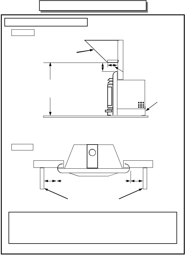
INSTALLATION INSTRUCTIONS
CLEARANCES TO COMBUSTIBLES
SIDE VIEW
Combustible mantle allowed in shaded area. Mantle extension may be increased
1” (25 mm) for each additional 1” (25 mm) increase in clearance height.
Minimum Height
From Top of
Surround: 6” (152 mm)
13” (330 mm)
Minimum Height From
Bottom of Appliance:
36” (915 mm)
Leveling leg
Non-combustible hearth is not required.*
*Observe building codes; the codes may require a non-combustible hearth.
TOP VIEW
|
|
|
|
|
|
|
|
|
|
|
|
|
|
|
|
|
|
|
|
3” (76 mm) |
|
3” (76 mm) |
|
|
|
|
|
|
|
Clearances to Surround
Sidewalls or Mantle Supports
CAUTION: This appliance is designed for use in any masonry, factory-built wood burning and specific zero-clearance vented gas fireplaces (Due to constant additions, contact Archgard Industries for an updated list of suitable gas fireplaces). This appliance cannot be enclosed with combustible material and used as a built-in gas fireplace.

25-BVI20N –2 |
9 |
|
|
INSTALLATION INSTRUCTIONS - Continued
MINIMUM MASONRY FIREPLACE DIMENSIONS
TOP VIEW
12” (305 mm)
17” (432 mm)
25” (635 mm)
SIDE VIEW |
Y |
Z |
X |
19 ½” (495 mm) |
The standard flue adapter will fit if X is more than 5 ¾”. It will also fit if X is less than 5 ¾” but Y is higher than 8” (See ‘Flue connector, offset vent’ diagram)
|
|
|
|
|
|
|
|
|
|
|
|
|
|
|
|
|
|
|
|
|
|
|
|
|
|
|
|
|
|
|
|
|
|
|
|
|
|
|
|
|
|
|
|
|
|
|
|
|
|
|
|
|
|
|
|
|
|
|
|
|
|
|
|
|
|
|
|
|
|
|
|
|
|
|
|
|
|
|
|
|
|
|
|
|
|
|
|
|
|
|
|
|
|
|
|
|
|
|
|
|
|
|
|
|
|
|
|
|
|
|
|
|
|
|
|
|
|
|
|
|
|
|
|
|
|
|
|
|
|
|
|
|
|
|
|
|
|
|
|
|
|
|
|
|
|
|
|
|
|
|
|
|
|
|
|
|
|
|
|
|
|
|
|
|
|
|
|
|
|
|
|
|
|
|
|
|
|
|
|
|
|
|
|
|
|
|
|
|
|
|
|
|
|
|
|
|
|
|
|
|
|
|
|
|
|
|
|
|
|
|
|
|
|
|
|
|
|
|
|
|
|
|
|
|
|
|
|
|
|
|
|
|
|
|
|
|
|
|
|
|
|
|
|
|
|
|
|
|
|
|
|
|
|
|
|
|
|
|
|
|
|
|
|
|
|
|
|
|
|
|
|
|
|
|
|
|
|
|
|
|
|
|
|
|
|
|
|
|
|
|
|
|
|
|
|
|
|
|
|
|
|
|
|
|
|
|
|
|
|
|
|
|
|
|
|
|
|
|
|
|
|
|
|
|
|
|
|
|
|
|
|
|
|
|
|
|
|
|
|
|
|
|
|
|
|
|
|
|
|
|
|
|
|
|
|
|
|
|
|
|
|
|
|
|
|
|
|
|
|
|
|
|
|
|
|
|
|
|
|
|
|
|
|
|
|
|
|
|
|
|
|
|
|
|
|
|
|
|
|
|
|
|
|
|
|
|
|
|
|
|
|
|
|
|
|
|
|
|
|
|
|
|
|
|
|
|
|
|
|
|
|
|
|
|
|
|
|
|
|
|
|
|
|
|
|
|
|
|
|
|
|
|
|
|
|
|
|
|
|
|
|
|
|
|
|
|
|
|
|
|
|
|
|
|
|
|
|
|
|
|
|
|
|
Flue connector |
|
|
|
|
|
|
|
Flue connector |
|
|
|
|
|
|
Flue connector |
|
|
|
|
Flue connector |
|||||||||||||||||||||||||||||||||||
|
|
|
|
straight-up vent |
|
|
|
|
|
|
|
offset vent |
|
|
|
|
|
|
straight-up vent |
|
|
|
|
|
offset vent |
||||||||||||||||||||||||||||||||||

25-BVI20N –2 |
10 |
|
|
INSTALLATION INSTRUCTIONS - Continued
MINIMUM ZERO-CLEARANCE WOOD BURNING FIREPLACE DIMENSIONS
TOP VIEW
12” (305 mm)
17” (432 mm)
25” (635 mm)
SIDE VIEW |
Y |
Z |
X |
15 ¼” (387 mm) |
The standard flue adapter will fit if X is more than 5 ¾”. It will also fit if X is less than 5 ¾” but Y is higher than 8” (See ‘Flue connector, offset vent’ diagram)
|
|
|
|
|
|
|
|
|
|
|
|
|
|
|
|
|
|
|
|
|
|
|
|
|
|
|
|
|
|
|
|
|
|
|
|
|
|
|
|
|
|
|
|
|
|
|
|
|
|
|
|
|
|
|
|
|
|
|
|
|
|
|
|
|
|
|
|
|
|
|
|
|
|
|
|
|
|
|
|
|
|
|
|
|
|
|
|
|
|
|
|
|
|
|
|
|
|
|
|
|
|
|
|
|
|
|
|
|
|
|
|
|
|
|
|
|
|
|
|
|
|
|
|
|
|
|
|
|
|
|
|
|
|
|
|
|
|
|
|
|
|
|
|
|
|
|
|
|
|
|
|
|
|
|
|
|
|
|
|
|
|
|
|
|
|
|
|
|
|
|
|
|
|
|
|
|
|
|
|
|
|
|
|
|
|
|
|
|
|
|
|
|
|
|
|
|
|
|
|
|
|
|
|
|
|
|
|
|
|
|
|
|
|
|
|
|
|
|
|
|
|
|
|
|
|
|
|
|
|
|
|
|
|
|
|
|
|
|
|
|
|
|
|
|
|
|
|
|
|
|
|
|
|
|
|
|
|
|
|
|
|
|
|
|
|
|
|
|
|
|
|
|
|
|
|
|
|
|
|
|
|
|
|
|
|
|
|
|
|
|
|
|
|
|
|
|
|
|
|
|
|
|
|
|
|
|
|
|
|
|
|
|
|
|
|
|
|
|
|
|
|
|
|
|
|
|
|
|
|
|
|
|
|
|
|
|
|
|
|
|
|
|
|
|
|
|
|
|
|
|
|
|
|
|
|
|
|
|
|
|
|
|
|
|
|
|
|
|
|
|
|
|
|
|
|
|
|
|
|
|
|
|
|
|
|
|
|
|
|
|
|
|
|
|
|
|
|
|
|
|
|
|
|
|
|
|
|
|
|
|
|
|
|
|
|
|
|
|
|
|
|
|
|
|
|
|
|
|
|
|
|
|
|
|
|
|
|
|
|
|
|
|
|
|
|
|
|
|
|
|
|
|
Flue connector |
|
|
|
|
|
|
|
|
Flue connector |
|
|
|
|
|
|
|
Flue connector |
|
|
|
|
|
Flue connector |
|||||||||||||||||||||||||||||||||||
|
|
|
|
|
straight-up vent |
|
|
|
|
|
|
|
|
offset vent |
|
|
|
|
|
|
|
straight-up vent |
|
|
|
|
|
|
offset vent |
||||||||||||||||||||||||||||||||||
25-BVI20N –2 |
11 |
|
|
INSTALLATION INSTRUCTIONS - Continued
To install the Euro 25 into a vented gas fireplace, see APPENDIX A (page 24) for installation instructions.
PRECAUTIONS
This appliance must be installed by a qualified gas installer and the installation must conform to the installation codes.
This appliance needs fresh air for safe operation and must be installed so there are provisions for adequate combustion and ventilation air. Provide adequate clearance around air openings of the appliance. Never obstruct front openings.
Provide adequate clearances for proper operation and servicing of the appliance.
This appliance must be properly connected to a suitable venting system and must not be connected to a chimney flue serving a separate solid fuel burning appliance.
This appliance is equipped with a three-prong (grounding) plug for your protection against shock hazard and should be plugged directly into a properly grounded three-prong receptacle.
VENTING
The appliance is equipped with a vent safety shutoff system and a safety control system designed to protect against improper venting of combustion products. The appliance will not function without being connected to a proper venting system.
The draft hood must be installed in the same room as the atmospheric pressure zone serving the unit for combustion air.
WARNING: Operation of this appliance when not connected to a properly installed and maintained venting system or tampering with the vent shut-off system can result in carbon monoxide (CO) poisoning and possible death.
This appliance must not be connected to a chimney flue serving a separate solid fuel burning appliance. The appliance may be vented using 4 in. diameter aluminum or stainless steel flexible gas liner running inside a masonry chimney or the flue of the factory-built fireplace. The vent system must be properly terminated with a suitable vent cap. The liner must form a complete connection from the flue collar to the vent cap. Follow the vent component manufacturer’s instruction. Also check with local gas authorities for proper venting methods and procedures.
Connecting the Vent Liner to the Appliance
Run the flexible gas liner down the chimney or flue. The appliance has a detachable flue adapter plate for ease of installation. Connect the the liner to the flue connector plate and fasten with screws and a 4” gear clamp. Before placing the appliance into the fireplace, check the hearth of the fireplace to see if it is level with the front of the fireplace. If it is not, measure the depth of the hearth. Loosen the three screws of the leveling “L” bracket at the back of the appliance. Lower it to the measurement obtained and tighten the screws. Make sure the gas and electrical supply line are properly connected to the appliance. Slide the appliance into the fireplace, and at the same time, slide the flue connector plate back onto the top of the appliance. Check the leveling of the appliance and attach the faceplate to the appliance before sliding the appliance all the way into the fireplace.

25-BVI20N –2 |
12 |
|
|
INSTALLATION INSTRUCTIONS - Continued
VENTING - Continued
Caution: Make sure the flue adapter plate is not too far back, or the appliance will not vent properly.
x
X = ¼” minimum
The arms can also be bent up and out of the way if the adapter plate is forward enough to interfere with the surround. The adapter plate must completely close with the appliance top plate.
GAS CONNECTIONS
Have your gas supplier or a qualified gas fitter run a gas supply line to the gas fireplace. The line must be properly sized and fitted according to the installation codes. Up stream of the supply connection, the fitter shall provide an accessible manual shut-off valve.
CAUTION: The appliance and its individual shutoff valve must be disconnected from the gas supply piping system during any pressure testing of that system at test pressures in excess of ½ psig (3.5 kPa). The appliance must be isolated from the gas supply piping system by closing its individual manual shutoff valve during any pressure testing of the gas supply piping system at test pressures equal to or less than ½ psig (3.5 kPa). Failure to do so will damage the appliance’s gas valve. Such damage is not covered by the manufacturer’s warranty.
Check for proper gas supply pressure by loosening the set screw on supply pressure tap (marked IN) on the gas valve with a small flat tip screw driver and placing a test gauge on the tap.
The minimum permissible gas supply pressure is 4.5 in. w.c. (1.2 kPa) for natural gas and 11.0 in. w.c. (2.8 kPa) for propane. Maximum gas supply pressure should never exceed 14.0 in. w.c. (3.6 kPa) or ½ psig. for both natural gas and propane.
BE SURE TO TIGHTEN THE PRESSURE TAP SET SCREW AFTER CHECKING THE PRESSURE, AND CHECK FOR GAS LEAKS.
Before connecting the appliance to the gas supply line, double check that the appliance you have purchased is designed for the gas type you are using. The gas type markings are located on the certification label and also on the tag attached to the appliance’s gas valve.
Adequate clearance for proper installation and checking of the gas connections must be provided. All gas connections must be checked for gas leaks.

25-BVI20N –2 |
13 |
|
|
INSTALLATION INSTRUCTIONS - Continued
ATTACHMENT OF FIREPLACE SURROUND
2
|
3 - THE SPILL SWITCH |
|
IS CONNECTED TO THE |
1 |
APPLIANCE (FACTORY- |
|
WIRED) |
1)The surround has four hooks that clip onto the sides of the appliance. Make sure the surround sits evenly with the front of the fireplace. After the surround is properly installed, the bottom edge of the centre section of the surround is about ¾” from the top of the appliance.
2)If needed, two securing brackets are provided to stabilize the appliance in shallow zeroclearance fireplaces. Screw these to the top of the appliance and to the face of the host fireplace. Use the holes on the bracket that best suit your application.
3)The spill switch is manual reset type that can be reset by pressing the pin between the two wire terminals with a small probe once the fireplace has cooled to the touch. This part is mounted on the unit and can be seen between the louvers once installed in the center top section. You will feel a small click once reset and the unit should relight. If the problem persists, call your dealer for technical assistance. Do not bypass this safety device.
A pilot shield is packaged with this unit in the event that it is required for installation. This is only required by the technician installing the unit if deemed necessary for cold pilot start up. Refer to the placement diagram below.
Part # 822-0060
 Loading...