

Page 1
C104
Downloaded from http://receiverfaq.ru/
1N0 SM
0V_SIG
R104
100R SM
EMC
Inputs
SK103
PHONO2G
1
TP100
F
N
TP101
PL100
1
2
2WVERTJUMPER
To microprocessor PCB
+24V_DIG
1
2
MUTE
3
OUT RLY
4
5
THERMPROT
6
VIPROT
7
DCPROT
8
9
FAULT
10
VIPROT
DC
THERM
FAULT
BASE1
BASE2
L924C2
L924C2_1.1.sch
INPUT
BASE1
BASE2
NFB
NB: Signals THERMPROT, VIPROT,
DCPROT and FAULT are open
collector outputs, active low,
referenced to 0V_DIG with no pull up
resistors
EMITTER1
EMITTER2
OUTPUT
SK104
10WAY-H-0.1-F
Microprocessor GND
Microprocessor +24V
MUTE not used
Output relay control
Not used
Thermal protection
SOA protection
DC offset protection
Overall fault signal
Not used
L924C3
L924C3_1.1.sch
EMITTER1
EMITTER2
OUTPUT
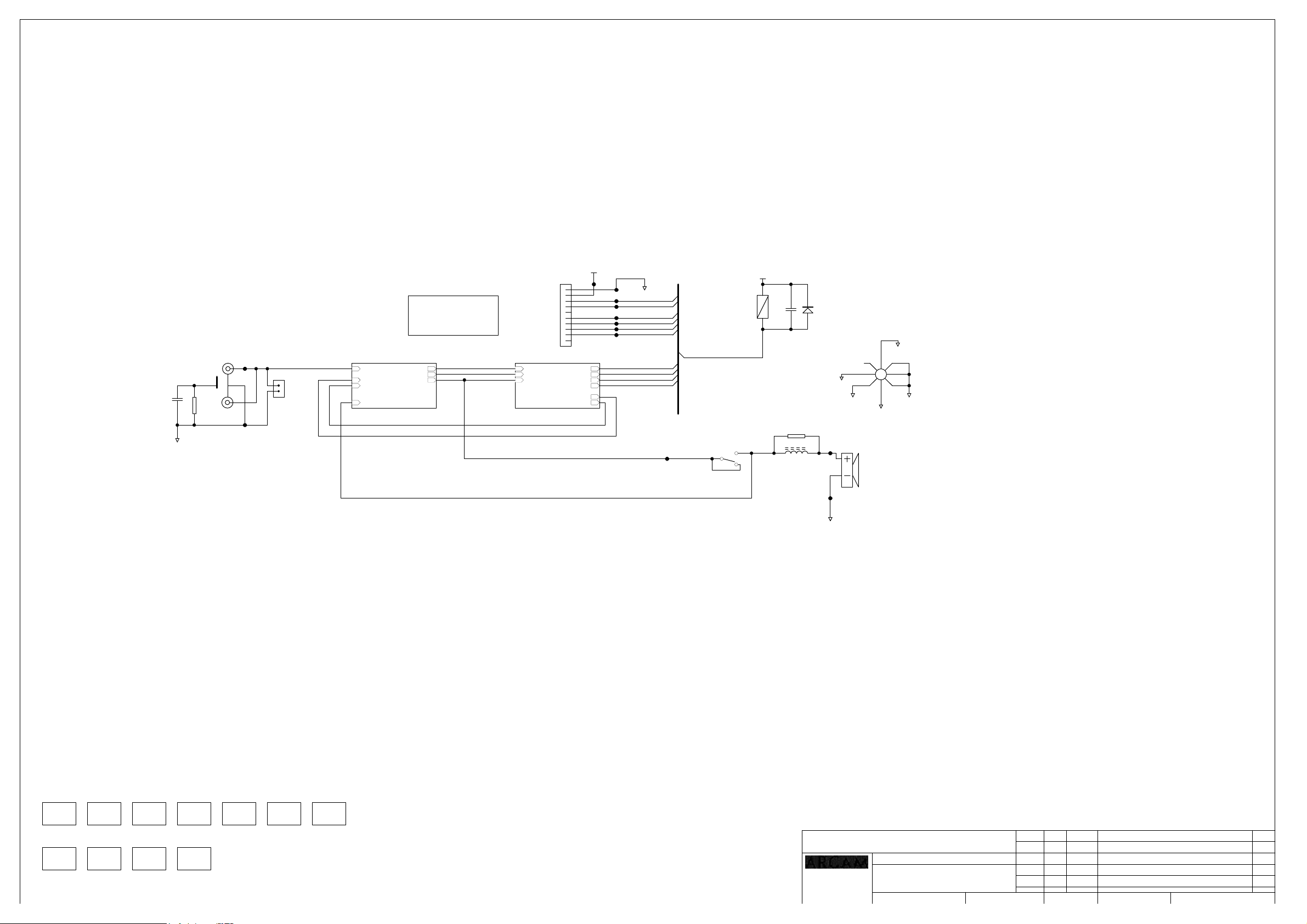
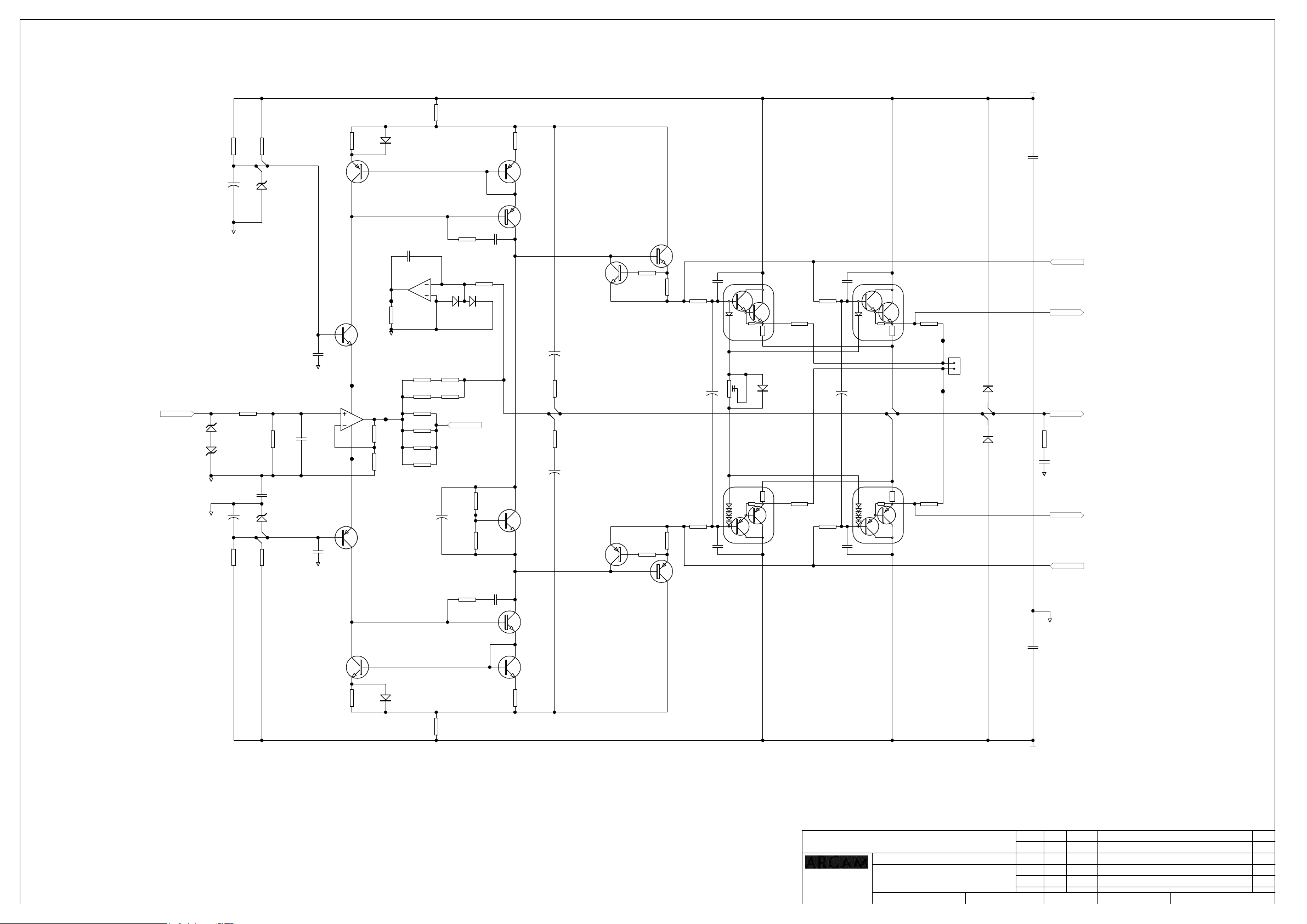
Amplifier circuit Protection and supplies
TP102
VIPROT
DCPROT
THERMPROT
FAULT
NB: Nets +24V_DIG and 0V_DIG are isolated from amplifier circuit
+24V_DIG
TP103
TP104
TP105
TP106
TP107
TP108
TP109
0V_DIG
RLY G2R-1E-24DC 16A SPDT
OUT RLY
RLY101A
RLY G2R-1E-24DC 16A SPDT
TP110
RLY101B
C103
100N SM
R103
2R2 MF
L101
2U2 AIR CORED
D101
BAS16W SM
Electrical ground star point
0V_HF
0V_PSU
TP111
SK105
0V_SIG
SP101
STAR_8
0V_LS0V_ZOB
Z100
PCB HEATSINK
L924PB
Z101
SUB PANEL
E107AY
Z102
E915HK
Z103
SUB PANEL SUB PANEL SUB PANEL
SCREW SCREW SCREW
HF4V09B
Z106
TRANSISTOR
INSULATOR
E950MC
Z104
HF4V09B
Z107
M3 TAPTITE M3 TAPTITE M3 TAPTITE M3 TAPTITE
HB3B12A
Z105
HF4V09B
Z108
HB3B12A
Z109
HB3B12A
Z110
HB3B12A
NB: Feedback around relay not fitted
4MM 2W HOR
TP112
0V_LS
DRAWING TITLE
A & R Cambridge Ltd.
Pembroke Avenue
Waterbeach
Cambridge CB5 9PB
P7 Amplifier Module
Filename:
L924C1_1.1.sch
Notes:
Contact Engineer:
02_E055 JR 4/3/2002 FIXED DC FAULT AT POWER ON SEQUENCE BY FEEDBACK 1.1
Contact Tel: (01223) 203200Jonny Reckless
ECO No. DESCRIPTION OF CHANGE
INITIALS
Printed:
DATE
7-Mar-2002
1 3Sheet of
DRAWING NO.
L924CT
ISSUE
Page 2
R219
220R MF
+55V
INPUT
DZ202
4V7 350MW SM
DZ203
4V7 350MW SM
0V_SIG
0V_HF
0V_HF
R210
27K SM
+
C203
100U EL
R223
1K0 SM
+
C204
100U EL
R212
27K SM
R211
27K SM
DZ200
15V 350MW SM
Input Filter
R228
22K SM
C201
100N SM
DZ201
15V 350MW SM
R213
27K SM
TR200
FMMT597
0V_SIG
C210
470P PPW
0V_SIG
TR205
FMMT497
C200
100N SM
3
2
C202
100N SM
R214
47R SM
TR204
FMMT497
0V_SIG
TP200
IC200A
TL072CD
84
TP202
1
R229
22R MF
R230
TP201
22R MF
V to I converter
TR203
FMMT597
R217
47R SM
D200
BAS16W SM
PNP current mirror
C212
470N PE
IC200B
TL072CD
7
TP203
R231
4K7 SM
Integrating DC servo
R232
560R MF
R233
560R MF
R236
NF
R237
NF
R238
NF
R239
NF
NPN current mirror
D202
BAS16W SM
TR202
TR PNP 2SA1740
C205
R221
3K3 SM
100P/250V
D203
BAV99W
+
C225
10U EL
NFB
R255
6K8 SM
R257
1K SM
R240
1M0 SM
TR212
FMMT497
6
5
R234
680R MF
R235
680R MF
R236 THRU R239 NOT FITTED
Pre driver bias
C207
R222
3K3 SM
100P/250V
TR206
TR NPN 2SC4548
R216
47R SM
TR201
FMMT597
TR207
FMMT497
R218
47R SM
+
C213
100U EL 100V
R241
1K CF 2W
Bootstrap
R242
1K CF 2W
+
C214
100U EL 100V
TR208
FMMT497
TR213
FMMT597
Pre driver
Pre driver
R207
100R SM
R245
22R SM
R246
22R SM
R208
100R SM
TR209
TR NPN 2SC4548
C217
47P/200V
R247
150R SM
C215
10U EL
R249
150R SM
C220
47P/200V
TR214
TR PNP 2SA1740
RV200
100R PSET
+
Trim output stage Iq
Output stage
TR210
SAP15N
R224
1K0 SM
D201
BAS16W SM
R226
1K0 SM
TR215
SAP15P
Output stage
C218
47P/200V
R248
150R SM
R250
150R SM
C221
47P/200V
+
C216
10U EL
TR211
SAP15N
R225
1K0 SM
Measure Iq
R227
1K0 SM
TR216
SAP15P
TP204
BIAS
PL200
1
2
TP205
D204
1N4003F
D205
1N4003F
C208
100N X7R 1812 500V
BASE1
EMITTER1
OUTPUT
R254
4R7 W2 CF
C223
47N PE
0V_ZOB
EMITTER2
BASE2
0V_HF
C209
100N X7R 1812 500V
R220
220R MF
DRAWING TITLE
A & R Cambridge Ltd.
Pembroke Avenue
Waterbeach
Cambridge CB5 9PB
P7 Amplifier Module
Filename:
L924C2_1.1.sch
Notes:
Contact Engineer:
-55V
02_E055 JR 4/3/2002 FIXED DC FAULT AT POWER ON SEQUENCE BY FEEDBACK 1.1
Contact Tel: (01223) 203200Jonny Reckless
ECO No. DESCRIPTION OF CHANGE
INITIALS
Printed:
DATE
7-Mar-2002
2 3Sheet of
DRAWING NO.
L924CT
ISSUE
Page 3
BASE1
EMITTER1
OUTPUT
EMITTER2
R338
330R SM
R339
330R SM
R300
100R SM
R301
100R SM
+55V
D308
22V 350MW SM
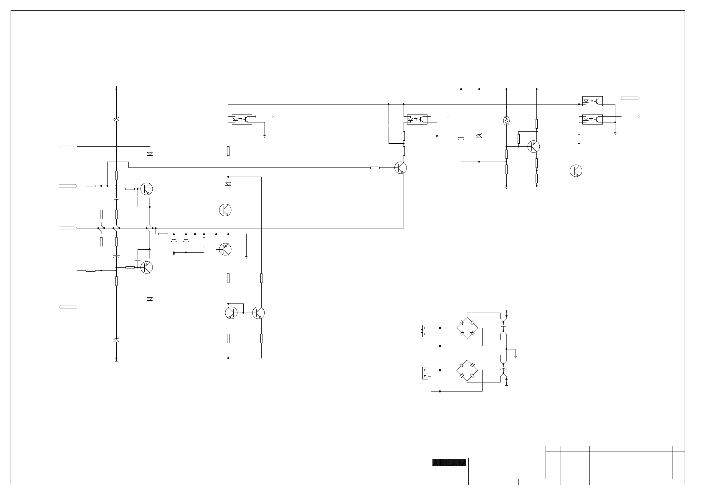
Instant SOA limiting
R340
10K SM
R302
100R SM
+
C318
100U EL
R335
22R SM
R336
22R SM
+
C319
100U EL
R311
100R SM
R341
10K SM
C305
100N SM
C306
100N SM
D300
BAS16W SM
TR309
FMMT497
R316
22K SM
C320
100U NP
TR305
FMMT597
DC offset detection
TP300
C321
100U NP
0V_HF
R334
4K7 SM
IC300A
OPTO-PC3Q66-QUAD-SM
R320
22K SM
D303
BAS16W SM
TR310
FMMT497
TR302
FMMT597
0V_HF
R332
22K SM
0V_DIG
R333
22K SM
R310
100R SM
C300
100N SM
IC300B
OPTO-PC3Q66-QUAD-SM
R321
22K SM
R337
1K SM
TR311
FMMT497
VIPROTDC
0V_DIG
+
C301
100U EL
TH300
PTH 110DEG SM
D301
15V 350MW SM
R342
120K SM
R307
39K SM
0V_HF
Over temperature sensing
R343
100K SM
R304
270R SM
TR301
FMMT597
R305
10K SM
R306
10K SM
IC300C
OPTO-PC3Q66-QUAD-SM
IC300D
OPTO-PC3Q66-QUAD-SM
R303
22K SM
TR300
FMMT497
FAULT
THERM
0V_DIG
BASE2
Instant SOA limiting
D309
22V 350MW SM
-55V
D307
BAS16W SM
TR312
FMMT497
R314
100R SM
TR313
FMMT497
R315
100R SM
AC from transformer
AC from transformer
SK300
MOLEXPWR2WAY_R/A
1
TP304
2
TP305
SK301
MOLEXPWR2WAY_R/A
1
TP306
2
TP307
DRAWING TITLE
A & R Cambridge Ltd.
Pembroke Avenue
Waterbeach
Cambridge CB5 9PB
Power supplies
1
BR300
+
BRGBU8D
3
~
3
~
2
~
-
4
1
+
BR301
BRGBU8D
2
~
-
4
P7 Amplifier Module
Filename:
Notes:
Contact Engineer:
L924C3_1.1.sch
+55V
TP302
+
C322
C AM 71V 10000U
0V_PSU
+
C323
C AM 71V 10000U
TP303
-55V
02_E055 JR 4/3/2002 FIXED DC FAULT AT POWER ON SEQUENCE BY FEEDBACK 1.1
Contact Tel: (01223) 203200Jonny Reckless
ECO No. DESCRIPTION OF CHANGE
INITIALS
Printed:
DATE
7-Mar-2002
3 3Sheet of
DRAWING NO.
L924CT
ISSUE
Page 4
Control PCB
L925CT1_1.2.SCH
Interface PCB
L925CT2_1.2.SCH
Main Switch and LED Display
L925CT3_1.2.sch
DRAWING TITLE
P7 Amp Controller
23425
A & R Cambridge Ltd.
Pembroke Avenue
Waterbeach
Cambridge CB5 9PB
Filename:
Notes:
Contact Engineer:
L925CT0_1.2.Sch
CHANGED R200 VALUE. CORRECTED SK301 & SK302 TO 8K2402
JP100 ADDED ON SK112 PIS 1 & 2 , F102 PART CORRECTED TO 315mA
ECO No. DESCRIPTION OF CHANGE
Contact Tel: (01223) 203252Kevin Lamb
INITIALS
Printed:
DATE
18-Apr-2002
1 4Sheet of
DRAWING NO.
L925CT
1.220/03/02KAL02_E061
1.17/03/02KAL02_E054 CHANGED C121 VALUE. REMOVED SOFT START PROTECTION
1.07/02/02KAL02_E041 PRODUCTION ISSUE PCB CHANGES ONLY
ISSUE
Page 5

15
2
6
3
7
4
8
SK100
TP109
AC_N
THERMAL TRIPS
FROM POWER
TRANSFORMERS
TP133
SK109
TX_THERM2
1
2
IDC2S
TP134
SK110
TX_THERM1
1
2
TP135
IDC2S
DGND_SK127
GND1
TP100
AC_L
C121
470N X2 CLASS
F100
T315MA
TP101
AUX_FUSE1
SK101
MOLEXPWR6
3
2
1
POWER TO AUX TRANSFORMER
TP110
AUX_AC2
TP111
AUX_AC1
1
2
SK107
MOLEXPWR4 D107
3
4
TP112
AUX_AC3
TP113
AUX_AC4
+5VD
R131
4K7 MF
R122
2K2 MF
GND1
6
5
4
+
F102
T315MA
TP102
AUX_FUSE2
D101
1N4003
D102
1N4003
D103
1N4003
D104
1N4003
D109
1N4148
+5VD
GND1
TH100
THERM NTC 2K2
C114
470U EL 25V
RELAY100A
RLY G2R-1E-24DC 16A SPDT
SK102
MOLEXPWR6
3
6
2
5
1
4
230V115V
R109
10K MF
TR101
BC547B
R137
100K MF
+
C115
10U EL
GND1
TREF
TTEMP
TR112
BC547B
D110
1N4148
X100
CST4.00
RESET*
TP103
AUX_TX
D105
1N4003
D106
1N4003
1N4003
D108
1N4003
C_DISCH
R123
2K2 MF
R100
RES 17W 150R
R101
RES 17W 150R
R102
RES 17W 150R
RC100
X2 100N/100R
RELAY101A
RLY G2R-1E-24DC 16A SPDT
+22VD
+
C101
3M3 35V EL
+5VD
R132
4K7 MF
PWROK*
+
C109
10U EL
GND1
D120
1N5711
TP156 TREF
TP157 C_DISCH
TP158 TTEMP
IC101B
IC 74HC259
VDD
GND
FIX100
FIX102
FIXING HOLE 3.5
FIXING HOLE 3.2
R103
100K 2W CF
F103
T4A
TP104
MAIN_FUSE1
SK103
MOLEXPWR6
3
2
1
6
5
4
F104
T4A
TP105
MAIN_FUSE2
SK104
MOLEXPWR6
3
2
1
TP114
MAIN_TX1
NF
6
5
4
230V 230V115V115V
F105
T4A
TP106
MAIN_FUSE3
SK105
MOLEXPWR6
3
2
1
6
5
4
D100
1N4003
NF
F106
T4A
TP107
MAIN_FUSE4
TP115
MAIN_TX2
SK106
MOLEXPWR6
3
2
1
IC105
1
2
3 4
4N35
NF
6
5
4
POWER TO MAIN TRANSFORMERS
HS100
TO220HS30REG
I
Vin
+
C102
1M0 25V
GND1
+5VD
R133
4K7 MF
FLT_TEMP*
GND1
+5VD
16
C117
100N CD
8
GND1
C103
100N PE
+5VD +5VD +5VD
R135
R134
4K7 MF
4K7 MF
FLT_VI*
FLT_DC*
TP136
MCLR
MAINS_SW
TX_OVTEMP
PWROK*
WATCHDOG
FLT_VI*
FLT_DC*
FLT_TEMP*
UC5V
C106
100N PE
IC102B
IC 74HC259
+5VD
16
VDD
C118
100N CD
8
GND
GND1
GND
G
GND1
TREF
TTEMP
PWM_OUT
C_DISCH
Vout
REG100
7805
S1
+5VD
O
+
C107
220U EL 50V
R136
4K7 MF
MAINS_SW
+5VD
SK112
1 2
3 4
5 6
GND1
DIL6 VPLG
IC100
1
MCLR
2
RA0
3
RA1
4
RA2
5
RA3
6
RA4/T0CKI
7
RA5/SS
8
RE0/RD
9
RE1/WR
10
RE2/CS
11
VDD
12
VSS
13
OSC1/CLKIN
14
OSC2/CLKOUT
15
RC0/T1OSI/T1CKI
16
RC1/T1OSO
17
RC2/CCP1
18
RC3/SCK/SCL
19
RD0/PSP0
RD1/PSP120RD2/PSP2
PIC16F877
IC103B
IC 74HC259
16
VDD
8
GND
+5VD
GND1
TP137 uC_+5V
JP100
JUMPER
RD7/PSP7
RD6/PSP6
RD5/PSP5
RD4/PSP4
RC5/SDO
RC4/SDI/SDA
RD3/PSP3
C119
100N CD
RB0/INT
UC5V
FAULT7*
40
RB7
RB6
RB5
RB4
RB3
RB2
RB1
VDD
VSS
RC7
RC6
FAULT6*
39
FAULT5*
38
FAULT4*
37
FAULT3*
36
FAULT2*
35
FAULT1*
34
TRIG/RC5
33
UC5V
32
31
GND1
SSPROT*
30
SEL_RELAY*
29
SEL_GRN*
28
SEL_RED*
27
RX
26
TX
25
MSOFT_ST*
24
MPOWER
23
DATAS0
22
S2
21
S1
S0
PWM_OUT
SK113
DIL6 VPLG+5VD
1 2
3 4
5 6
GND1
IC104C
+5VD
LM393A
84
C120
100N CD
GND1
GND1
+5VD
R110
10K MF
C105
100N PE
TP108
6
MSSPROT
5
GND1
WATCHDOG
+5VD
R104
47K MF
SSPROT*
+
C100
4U7 50V
NF
GND1
+22VD
F101
R114
100K MF
DATA
S0
S1
S2
SEL_RED*
RESET*
DATA
S0
S1
S2
SEL_GRN*
DATA
S0
S1
S2
SEL_RELAY*
T315MA
PWM_OUT
+5VD
R106
22K MF
R105
47K MF
GND1
+
C110
10U EL
IC101A
D13Q0
S01Q2
S12Q3
S23Q4
G14Q6
CLR15Q7
IC 74HC259
IC102A
D13Q0
S01Q2
S12Q3
S23Q4
G14Q6
CLR15Q7
IC 74HC259
IC103A
D13Q0
S01Q2
S12Q3
S23Q4
G14Q6
CLR15Q7
IC 74HC259
R107
22K MF
RED1
4
RED2
5
Q1
RED3
6
RED4
7
RED5
9
RED6
10
Q5
RED7
11
12
GRN1
4
GRN2
5
Q1
GRN3
6
GRN4
7
GRN5
9
GRN6
10
Q5
GRN7
11
12
RELAY1
4
RELAY2
5
Q1
RELAY3
6
RELAY4
7
RELAY5
9
RELAY6
10
Q5
11
RELAY7
12
+
+
C111
10U EL
C116
47U EL 35V
IC104A
3
2
LM393A
IC104B
5
6
LM393A
GND1
TP159 RELAY1
TP160 RELAY2
TP161 RELAY3
TP142 RELAY4
TP162 RELAY5
TP163 RELAY6
TP164 RELAY7
1
7
R112
100K MF
+22VD +22VD_SW
R108
10K MF
R111
2K2 MF
R119
10K MF
TR103
BC547B
D111
1N4148
TP138
RELAY1*
TR102
TR104
BC547B
BC547B
R124
R125
2K2 MF
2K2 MF
RELAY1
RELAY2
+
C108
10U EL
MAINS_SW
+22VD_SW
TR116
BD180 PNP TO-126
D112
1N4148
TP139
RELAY2*
TR105
BC547B
R126
2K2 MF
RELAY3
R115
100R MF
TR100
BC547B
R117
470R MF
R116
100R MF
TR113
BC557B TR114
D113
1N4148
TP140
RELAY3*
GND1
TR106
BC547B
R127
2K2 MF
RELAY4
MPOWER
MSOFT_ST*
D114
1N4148
TP141
RELAY4
BC557B
R113
100K MF
RELAY5
TR107
BC547B
R128
2K2 MF
2K2 MF
R120
2K2 MF
R121
2K2 MF
R118
C112
1N PE
D115
1N4148
TR108
BC547B
GND1
D116
1N4148
TP143
RELAY5*
TR109
BC547B
R129
2K2 MF
RELAY6
GND1
TR115
2SC5248
HS101
TO220HS30TR
C104
100N PE
PCB NET LINK
RELAY100B
RLY G2R-1E-24DC 16A SPDT
+22VD_SW
D117
1N4148
TP144
RELAY6*
TR110
BC547B
R130
2K2 MF
RELAY7
DRAWING TITLE
23425
A & R Cambridge Ltd.
Pembroke Avenue
Waterbeach
Cambridge CB5 9PB
LK1
D119
1N4148
TR111
BC547B
D118
1N4148
TP145
RELAY7*
GND1
P7 Amp Controller
Filename:
Notes:
Contact Engineer:
RELAY101B
RLY G2R-1E-24DC 16A SPDT
GND1
TP146FAULT1
TP147FAULT2
TP148FAULT3
TP149FAULT4
TP150FAULT5
TP151FAULT6
TP152FAULT7
L925CT1_1.2.sch
FIX103
FIXING HOLE 3.5
FIX104
FIXING HOLE 3.5
FIX101
FIXING HOLE 3.2
FIX105
FIXING HOLE 3.5
PB
PCB
L925PB_E
+
C113
470U EL 25V
TP116RED1
TP117RED2
TP118RED3
TP119RED4
TP120RED5
TP121RED6
TP122RED7
Contact Tel: (01223) 203252Kevin Lamb
TP131
SK108
FAN
1
2
IDC2S
TP130
DGND_FAN
SK111
RED1
RED2
RED3
RED4
RED5
RED6
RED7
TP123GRN1
TP124GRN2
TP125GRN3
TP126GRN4
TP127GRN5
TP128GRN6
TP129GRN7
TP153FLT_DC*
TP154FLT_VI*
TP155FLT_TEMP*
+22VD_SW
TRIG/RC5
ECO No. DESCRIPTION OF CHANGE
INITIALS
Printed:
1
2
3
4
5
6
7
8
GRN1
9
GRN2
10
GRN3
11
GRN4
12
GRN5
13
GRN6
14
GRN7
15
16
FFC16V
GND1
TP132
MAINS_SW
SK114
FAULT1*
22
FAULT2*
21
FAULT3*
20
FAULT4*
19
FAULT5*
18
FAULT6*
17
FAULT7*
16
FLT_DC*
15
FLT_VI*
14
FLT_TEMP*
13
12
RELAY1*
11
RELAY2*
10
RELAY3*
9
RELAY4*
8
RELAY5*
7
RELAY6*
6
RELAY7*
5
4
3
2
TP166
1
+22V
FFC22V1MM
TP165
TP167
DGND_SK131
GND1
CHANGED R200 VALUE. CORRECTED SK301 & SK302 TO 8K2402
JP100 ADDED ON SK112 PIS 1 & 2 , F102 PART CORRECTED TO 315mA
DATE
18-Apr-2002
2 4Sheet of
DRAWING NO.
L925CT
1.220/03/02KAL02_E061
1.17/03/02KAL02_E054 CHANGED C121 VALUE. REMOVED SOFT START PROTECTION
1.07/02/02KAL02_E041 PRODUCTION ISSUE PCB CHANGES ONLY
ISSUE
Page 6

SK201
JACK3.5
C201
1N0 CD
CHASSIS CHASSIS
TP202
RC5_TRIG
GND_RC5_TRIG
C202
1N0 CD
TP207
GND2 GND2
R200
1K0 MF
R202
1K0 MF
D200
4V7 400MW
GND2
R201
2K2 MF
SK200
1
2
3
4
5
6
7
8
9
10
11
12
13
14
15
16
17
18
19
20
21
22
FFC22V1MM
TP203
DGND_SK206
GND2
AFAULT1
AFAULT2
AFAULT3
AFAULT4
AFAULT5
AFAULT6
AFAULT7
AFLT_DC*
AFLT_VI*
AFLT_TEMP*
ARELAY1*
ARELAY2*
ARELAY3*
ARELAY4*
ARELAY5*
ARELAY6*
ARELAY7*
TP204 A+22VD
FIX202
FIXING HOLE 3.5
+22VD_SW2
C200
100N CD
GND2
FIX200
FIXING HOLE 3.2
FIX203
FIXING HOLE 3.5
CHASSIS
FIX204
FIXING HOLE 3.5
FIX205
FIXING HOLE 3.5
FIX206
FIXING HOLE 3.5
FIX207
FIXING HOLE 3.5
FIX201
FIXING HOLE 3.2
+22VD_SW2
TP200RELAY1
TP201RELAY2
TP206RELAY3
TP205RELAY4
TP208RELAY5
TP209RELAY6
TP210RELAY7
ARELAY1*
ARELAY2*
ARELAY3*
ARELAY4*
ARELAY5*
ARELAY6*
ARELAY7*
ASIG_PRES*
AFLT_TEMP*
AFLT_VI*
AFLT_DC*
ASIG_PRES*
AFLT_TEMP*
AFLT_VI*
AFLT_DC*
ASIG_PRES*
AFLT_TEMP*
AFLT_VI*
AFLT_DC*
ASIG_PRES*
AFLT_TEMP*
AFLT_VI*
AFLT_DC*
ASIG_PRES*
AFLT_TEMP*
AFLT_VI*
AFLT_DC*
ASIG_PRES*
AFLT_TEMP*
AFLT_VI*
AFLT_DC*
ASIG_PRES*
AFLT_TEMP*
AFLT_VI*
AFLT_DC*
AFAULT1
+22VD_SW2
AFAULT2
+22VD_SW2
AFAULT3
+22VD_SW2
AFAULT4
+22VD_SW2
AFAULT5
+22VD_SW2
AFAULT6
+22VD_SW2
AFAULT7
GND2
GND2
GND2
GND2
GND2
GND2
GND2
PL200
1
2
3
4
5
6
7
8
9
10
CON 10W 0.1 HDR
PL201
1
2
3
4
5
6
7
8
9
10
CON 10W 0.1 HDR
PL202
1
2
3
4
5
6
7
8
9
10
CON 10W 0.1 HDR
PL203
1
2
3
4
5
6
7
8
9
10
CON 10W 0.1 HDR
PL204
1
2
3
4
5
6
7
8
9
10
CON 10W 0.1 HDR
PL205
1
2
3
4
5
6
7
8
9
10
CON 10W 0.1 HDR
PL206
1
2
3
4
5
6
7
8
9
10
CON 10W 0.1 HDR
DRAWING TITLE
23425
A & R Cambridge Ltd.
Pembroke Avenue
Waterbeach
Cambridge CB5 9PB
P7 Amp Controller
Filename:
L925CT2_1.2.Sch
Notes:
Contact Engineer:
CHANGED R200 VALUE. CORRECTED SK301 & SK302 TO 8K2402
JP100 ADDED ON SK112 PIS 1 & 2 , F102 PART CORRECTED TO 315mA
INITIALS
Printed:
DATE
18-Apr-2002
3 4Sheet of
DRAWING NO.
L925CT
Contact Tel: (01223) 203252Kevin Lamb
ECO No. DESCRIPTION OF CHANGE
ISSUE
1.220/03/02KAL02_E061
1.17/03/02KAL02_E054 CHANGED C121 VALUE. REMOVED SOFT START PROTECTION
1.07/02/02KAL02_E041 PRODUCTION ISSUE PCB CHANGES ONLY
Page 7

SK301
1
2
8K2402
SW300A
MAINS_SW A1007
SW300B
MAINS_SW A1007
SK300
16
15
14
13
12
11
10
9
8
7
6
5
4
3
2
1
FFC16V
BRED1
BGRN1
MAINS_SW1
BRED1
BRED2
BRED3
BRED4
BRED5
BRED6
BRED7
BGRN1
BGRN2
BGRN3
BGRN4
BGRN5
BGRN6
BGRN7
MAINS_SW1
TP315
DGND_SK302
GND3
BRED1
BRED2
BRED3
BRED4
BRED5
BRED6
BRED7
BGRN1
BGRN2
BGRN3
BGRN4
BGRN5
BGRN6
BGRN7
R300
220R MF
R
GND3
LED300
LED RED/GRN
R301
220R MF
G
FIX302
FIXING HOLE 3.5
FIX300
FIXING HOLE 3.2
TP300RED1
TP301RED2
TP302RED3
TP303RED4
TP304RED5
TP305RED6
TP306RED7
TP307GRN1
TP308GRN2
TP309GRN3
TP310GRN4
TP311GRN5
TP312GRN6
TP313GRN7
TP314DMAIN_SW
R302
220R MF
R
LED301
LED RED/GRN
BRED2
BGRN2
R303
220R MF
GND3
FIX303
FIXING HOLE 3.5
FIX301
FIXING HOLE 3.2
BRED3
BGRN3
R304
220R MF
G
R
LED302
LED RED/GRN
GND3
R305
220R MF
G
R306
220R MF
R
BRED4
GND3
LED303
LED RED/GRN
BGRN4
R307
220R MF
G
R308
220R MF
R
BRED5
GND3
LED304
LED RED/GRN
BGRN5
R309
220R MF
G
R310
220R MF
R
BRED6
GND3
LED305
LED RED/GRN
BGRN6
R311
220R MF
G
R312
220R MF
R
BRED7
BGRN7
R313
220R MF
G
GND3 GND3
LED306
LED RED/GRN
1
2
SK302
8K2402
MAINS_SW1
DRAWING TITLE
P7 Amp Controller
23425
A & R Cambridge Ltd.
Pembroke Avenue
Waterbeach
Cambridge CB5 9PB
Filename:
Notes:
Contact Engineer:
L925CT3_1.2.Sch
CHANGED R200 VALUE. CORRECTED SK301 & SK302 TO 8K2402
JP100 ADDED ON SK112 PIS 1 & 2 , F102 PART CORRECTED TO 315mA
ECO No. DESCRIPTION OF CHANGE
Contact Tel: (01223) 203252Kevin Lamb
INITIALS
Printed:
DATE
18-Apr-2002
4 4Sheet of
DRAWING NO.
L925CT
1.220/03/02KAL02_E061
1.17/03/02KAL02_E054 CHANGED C121 VALUE. REMOVED SOFT START PROTECTION
1.07/02/02KAL02_E041 PRODUCTION ISSUE PCB CHANGES ONLY
ISSUE
Page 8

87654321
windings connect to 2 way molex connector 39-01-3028. Use MOLEX pin
Transformer Specification For 115/230V P7 transformer
Arcam Part Number L911TX
Material Safety Specification
1. Winding Wire to be Grade 2 (130C rating) to BS 60317-4 1995
2. Mylar Polyester Insulator 130C Rated
D
C
3. Potting Compound PC3502 E135297(M)
Mechanical Specification
1. Middle of transformer to be potted (as shown).
2. Primary windings connect to 6 way MOLEX connector 39-01-2065.
Secondary
44476-3112.
MOLEX connectors have pin numbers indicated on them.
3. Primary wires are enclosed in a common sleeve. Each secondary
winding is individually sleeved.
Use PVC sleeving.
4. All wire lengths in mm. Lengths are +5.0, -0
5. Please adhere rubber insulating pad to bottom of transformer as shown.
Electrical Specification
1. Transformer to have dual 115V primaries to allow parallel operation for
115V input and series operation with 230V input.
2. Transformer input voltage range
115V -18% +14% (97.5V to 132.5V)
230V -18% +14% (195V to 265V)
3. Transformer to have 7 secondary windings as show in the adjacent
drawing.
4. Loaded DC voltages specified at 230V AC in (with transformer primaries
in series)
5. Each secondary winding to have a full wave (4diode) bridge to produce a
single DC rail.
(AS shown in diagram)
Output Capacitance to be 10000uF per rail.
VOUTmin = 52V dc @ Io = 2A (with 230V AC in) See dwg
This figure to be the minimum voltage on the reservoir capacitor as shown
in the diagram
5 1
46 2
12
3
Pin outs of Molex connectors
As viewed looking down at the end
the wires enter the connector
Connector Latch
2 way6 way
PRIMARY WIRES
LEADS EXIT FROM BOTTOM
145mm dia max
Rubber insulating pad
SECONDARY WIRES
LEADS EXIT FROM BOTTOM
POTTING COMPOUND
M12 Threaded Brass Insert
INSERT TO ALLOW 30mm DEPTH OF THREAD
1
2
3
4
5
6
95max
PRIMARY
6 WAY CONN PIN 1
115V ac
6 WAY CONN PIN 3
6 WAY CONN PIN 4
115V ac
6 WAY CONN PIN 6
BROWN
WHITE
BLACK
BLUE
SECONDARY
RED
OR
RED
OR
RED
OR
RED
OR
RED
OR
RED
OR
RED
OR
100C THERMAL TRIP
NORMALLY CLOSED
RESETTABLE
SCREEN WIRE GRN/YELL
1
2
1
2
1
2
1
2
1
2
1
2
1
2
1
2
2WAY 10-11-2023 molex
M4 CRIMP EYELET
D
C
B
Voltage on Reservoir Capacitor
6 way MOLEX 39-01-2065
52V
10mS
VOUT min
UL94- V0
2WAY 10-11-2023 molex
TEST CIRCUIT (PER OUTPUT)
+VOUT
AC IN
+
10000uF
A
1 2 3 4 5 6 7 8
-VOUT
2A load
A & R Cambridge Ltd.
Pembroke Avenue
Denny Industrial Centre
Waterbeach
Cambridge CB5 9PB
Filename
J:\Development_Projects\P7_Amp\Transformer Design\L911TX_1.ddb - Documents\L911TX_1.sch
23425
PRIMARIES
THERMAL TRIP
SCREEN WIRE
M4 CRIMP EYELET
200mm
280mm
280mm
DRAWING TITLE
POWER TRANSFORMER FOR P7 115/230V
Circuit Diagram
Notes:
ECO No. DESCRIPTION OF CHANGE
INITIALS
SECONDARY 1
DATE
Date Printed
6-Mar-2002
2 way MOLEX 39-01-3028
FOR LENGTH OF SECONDARIES
SEE TABLE BELOW
SECONDARY 7
2 way MOLEX 39-01-3028
SECONDARY LENGTH
1
2
3
4
5
6
7
Lead Out Changes to suit new wiring arrangement in amplifier
Lead Out Changes
Drawn by:
KAL
1 1Sheet of
520
560
550
570
570
610
650
DRAWING NO.
ISSUE
L911TX
B
A
105-03-2002KAL
D4-12-2001KAL Mechanical Changes
Page 9

4321
windings connect to 4 way molex connector 39-01-3048. Use MOLEX pin 44476-3112.
(this will ensure that VOUT2 is 8V at 195V AC in)
Transformer Specification For 115/230V P7 Auxilliary Transformer
Arcam Part Number L912TX
PRIMARY SECONDARY
6 WAY CONN PIN 3
D
BROWN
RED
4 WAY CONN PIN 3
115V ac
6 WAY CONN PIN 1
6 WAY CONN PIN 6
WHITE
BLACK
ORANGE
YELLOW 4 WAY CONN PIN 2
4 WAY CONN PIN 4
115V ac
6 WAY CONN PIN 4
BLUE
PURPLE
4 WAY CONN PIN 1
TEST CIRCUIT (PER OUTPUT)
TEST CIRCUIT
1N4003 1N4003
1N4003 1N4003
+
3300uF
VOUT 1
500mA load
Amthyst Part Number AD3595T
Material Safety Specification
D
1. Winding Wire to be Grade 2 (130C rating) to BS 60317-4 1995
2. Mylar Polyester Insulator 130C Rated
3. Potting Compound PC3502 E135297(M)
Mechanical Specification
1. Middle of transformer to be potted. Potting to be drilled out with an 6mm DIA Hole
and then the bottom surface counterbored to a depth of 12mm with a 12mm dia drill
as shown. Actual part which the counterbore is designed to clear extends up to 10mm from
transformer mounting surface into counterbore.
C
B
Vout1 = 22V
Vout2 = 9.5V
60 max
CENTRE TO BE POTTED AND DRILLED
OUT TO 6mm DIA
35mm
Voltage on Reservoir Capacitor
10mS
90mm
PRIMARIES
SECONDARIES
110mm
12mm
40 max
DRAWING TITLE
AUX TOROIDAL TRANSFORMER FOR P7 AMP 115/230V
1N4003 1N4003
1N4003 1N4003
6 way MOLEX 39-01-2065
UL94-V0
4 way MOLEX 39-01-3048
VOUT 2
+
1000uF
5346
12
Pin outs of Molex connectors
As viewed looking down at the end
the wires enter the connector
GND
150mA load
GND
3
4
1
2
4 way6 way
2. Primary windings connect to 6 way MOLEX 39-01-2065. Secondary
MOLEX connectors have pin numbers indicated on them.
3. Use 24 AWG wire with colours as shown. Primary wires are enclosed in a common
sleeve. Secondary wires are enclosed in a common screen. Use PVC sleeving.
4. All wire lengths in mm. Lengths are +5.0, -0
5. Please adhere rubber insulating pad to bottom of transformer as shown.
Electrical Specification
1. Transformer to have dual 115V primaries to allow parrallel operation for
115V input and series operation with 230V input.
2. Transformer input voltage range
115V -18% +14% (97.5V to 132.5V)
230V -18% +14% (195V to 265V)
3. Transformer to have two secondary windings as show in the adjacent drawing.
4. Loaded DC voltages specified at 230V AC in (with transformer primaries in series)
DC supplies to be generated by configuring the seconday windings with a full wave bridge
(see diagram).
Output Capacitance to be 3300uF. 22V dc
Output Capacitance to be 1000uF. 9.5V dc
VOUT1 = 22.0V dc @ Io = 250mA (With 230V AC in)
V0UT2 = 9.5V dc @ Io = 150mA (With 230V AC in)
C
B
A
COUNTERBORE DIA 12mm
COUNTERBORE DEPTH 12mm
23425
A & R Cambridge Ltd.
Pembroke Avenue
Denny Industrial Centre
Rubber insulating pad
1 2 3 4
Waterbeach
Cambridge CB5 9PB
Circuit Diagram
Notes:
ECO No. DESCRIPTION OF CHANGE
Filename
J:\Development_Projects\P7_Amp\Transformer Design\L912tx_1.ddb - Documents\L912TX_1.Sch
INITIALS
05/03/2002KAL Changed counterbore details and numerous corrections.
04/12/2001KAL Changed Lead Lengths
DATE
Date Printed
6-Mar-2002
Drawn by:
KAL
1 1Sheet of
DRAWING NO.
A
1
F
ISSUE
L912TX
Page 10

87654321
windings connect to 2 way molex connector 39-01-3028. Use MOLEX pin
Transformer Specification For 100V P7 Amplifier
Arcam Part Number L920TX
Material Safety Specification
1. Winding Wire to be Grade 2 (130C rating) to BS 60317-4 1995
2. Mylar Polyester Insulator 130C Rated
D
C
3. Potting Compound PC3502 E135297(M)
Mechanical Specification
1. Middle of transformer to be potted (as shown).
2. Primary windings connect to 6 way MOLEX connector 39-01-2065.
Secondary
44476-3112.
MOLEX connectors have pin numbers indicated on them.
3. Primary wires are enclosed in a common sleeve. Each secondary
winding is individually sleeved.
Use PVC sleeving.
4. All wire lengths in mm. Lengths are +5.0, -0
5. Please adhere rubber insulating pad to bottom of transformer as shown.
Electrical Specification
1. Transformer to have dual 100V primaries to allow parallel operation for
100V input
2. Transformer input voltage range
100V -18% +14% (82V to 114V)
3. Transformer to have 7 secondary windings as show in the adjacent
drawing.
4. Loaded DC voltages specified at 100V AC in (with transformer primaries
in parallel)
5. Each secondary winding to have a full wave (4diode) bridge to produce a
single DC rail.
(AS shown in diagram)
Output Capacitance to be 10000uF per rail.
VOUTmin = 52V dc @ Io = 2A (with 100V AC in) See dwg
This figure to be the minimum voltage on the reservoir capacitor as shown
in the diagram
5 1
46 2
12
3
Pin outs of Molex connectors
As viewed looking down at the end
the wires enter the connector
Connector Latch
2 way6 way
PRIMARY WIRES
LEADS EXIT FROM BOTTOM
145mm dia max
Rubber insulating pad
SECONDARY WIRES
LEADS EXIT FROM BOTTOM
POTTING COMPOUND
M12 Threaded Brass Insert
INSERT TO ALLOW 30mm DEPTH OF THREAD
1
2
3
4
5
6
95max
PRIMARY
6 WAY CONN PIN 1
100V ac
6 WAY CONN PIN 3
6 WAY CONN PIN 4
100V ac
6 WAY CONN PIN 6
BROWN
WHITE
BLACK
BLUE
SECONDARY
RED
OR
RED
OR
RED
OR
RED
OR
RED
OR
RED
OR
RED
OR
100C THERMAL TRIP
NORMALLY CLOSED
RESETTABLE
SCREEN WIRE GRN/YELL
1
2
1
2
1
2
1
2
1
2
1
2
1
2
1
2
2WAY 10-11-2023 molex
M4 CRIMP EYELET
D
C
B
Voltage on Reservoir Capacitor
6 way MOLEX 39-01-2065
52V
10mS
VOUT min
UL94- V0
2WAY 10-11-2023 molex
TEST CIRCUIT (PER OUTPUT)
+VOUT
AC IN
+
10000uF
A
1 2 3 4 5 6 7 8
-VOUT
2A load
A & R Cambridge Ltd.
Pembroke Avenue
Denny Industrial Centre
Waterbeach
Cambridge CB5 9PB
Filename
J:\Development_Projects\P7_Amp\Transformer Design\L920TX_1.ddb - Documents\L920TX_1.sch
23425
PRIMARIES
THERMAL TRIP
SCREEN WIRE
M4 CRIMP EYELET
200mm
280mm
280mm
DRAWING TITLE
POWER TRANSFORMER FOR P7 100V (JAPAN)
Circuit Diagram
Notes:
ECO No. DESCRIPTION OF CHANGE
INITIALS
SECONDARY 1
DATE
Date Printed
6-Mar-2002
FOR LENGTH OF SECONDARIES
SEE TABLE BELOW
SECONDARY 7
SECONDARY LENGTH
1
2
3
4
5
6
7
Drawn by:
KAL
2 way MOLEX 39-01-3028
520
560
550
570
570
610
650
1 1Sheet of
DRAWING NO.
2 way MOLEX 39-01-3028
ISSUE
L920TX
B
A
105-03-2002KAL Based on spec of 115/230V part (L911TX)
Page 11

4321
windings connect to 4 way molex connector 39-01-3048. Use MOLEX pin 44476-3112.
Transformer Specification For 100V (JAPAN) P7 Auxilliary Transformer
Arcam Part Number L921TX
PRIMARY SECONDARY
6 WAY CONN PIN 3
D
BROWN
RED
4 WAY CONN PIN 3
100V ac
6 WAY CONN PIN 1
6 WAY CONN PIN 6
WHITE
BLACK
ORANGE
YELLOW 4 WAY CONN PIN 2
4 WAY CONN PIN 4
100V ac
6 WAY CONN PIN 4
BLUE
PURPLE
4 WAY CONN PIN 1
TEST CIRCUIT
1N4003 1N4003
1N4003 1N4003
+
3300uF
VOUT 1
500mA load
Material Safety Specification
1. Winding Wire to be Grade 2 (130C rating) to BS 60317-4 1995
D
2. Mylar Polyester Insulator 130C Rated
3. Potting Compound PC3502 E135297(M)
Mechanical Specification
1. Middle of transformer to be potted. Potting to be drilled out with an 6mm DIA Hole
and then the bottom surface counterbored to a depth of 12mm with a 12mm dia drill
as shown. Actual part which the counterbore is designed to clear extends up to 10mm from
transformer mounting surface into counterbore.
TEST CIRCUIT (PER OUTPUT)
2. Primary windings connect to 6 way MOLEX 39-01-2065. Secondary
Voltage on Reservoir Capacitor
VOUT 2
GND
MOLEX connectors have pin numbers indicated on them.
C
B
Vout1 = 22V
Vout2 = 9.5V
60 max
CENTRE TO BE POTTED AND DRILLED
OUT TO 6mm DIA
35mm
12mm
40 max
10mS
90mm
PRIMARIES
SECONDARIES
110mm
1N4003 1N4003
1N4003 1N4003
6 way MOLEX 39-01-2065
UL94-V0
4 way MOLEX 39-01-3048
DRAWING TITLE
AUX TOROIDAL TRANSFORMER P7 100V (JAPAN)
+
1000uF
5346
12
Pin outs of Molex connectors
As viewed looking down at the end
the wires enter the connector
150mA load
GND
3
4
1
2
4 way6 way
3. Use 24 AWG wire with colours as shown. Primary wires are enclosed in a common
sleeve. Secondary wires are enclosed in a common screen. Use PVC sleeving.
4. All wire lengths in mm. Lengths are +5.0, -0
5. Please adhere rubber insulating pad to bottom of transformer as shown.
Electrical Specification
1. Transformer to have dual 100V primaries to allow parallel operation for
100V input.
2. Transformer input voltage range
100V -18% +14% (82V to 114V)
3. Transformer to have two secondary windings as show in the adjacent drawing.
4. Loaded DC voltages specified at 100V AC in (with transformer primaries in parallel)
DC supplies to be generated by configuring the seconday windings with a full wave bridge
(see diagram).
Output Capacitance to be 3300uF. 22V dc
Output Capacitance to be 1000uF. 9.5V dc
VOUT1 = 22.0V dc @ Io = 250mA (With 100V AC in)
V0UT2 = 9.5V dc @ Io = 150mA (With 100V AC in)
(this will ensure that VOUT2 is 8V at 82V AC in)
C
B
A
COUNTERBORE DIA 12mm
COUNTERBORE DEPTH 12mm
23425
A & R Cambridge Ltd.
Pembroke Avenue
Denny Industrial Centre
Rubber insulating pad
1 2 3 4
Waterbeach
Cambridge CB5 9PB
Circuit Diagram
Notes:
ECO No. DESCRIPTION OF CHANGE
Filename
J:\Development_Projects\P7_Amp\Transformer Design\L921tx_1.ddb - Documents\L921TX_1.Sch
INITIALS
05/03/2002KAL Based on spec of 115/230V part (L912TX)
DATE
Date Printed
6-Mar-2002
Drawn by:
KAL
1 1Sheet of
DRAWING NO.
A
1
ISSUE
L921TX
 Loading...