

Arcam FMJ AV-8 Service manual
Service Manual
ARCAM
FMJ AV8
Preamp Processor
AV8
Issue 2.0
ARCAM

Contents List
Section Issue
Manual Updates
! Service Manual changes issue 1.0 to 2.0 -
Technical specifications
! Front & rear view diagram -
! Dimension diagram -
! Specification -
Service guide
! Engineering Mode -
! AV8 Programmer software -
! AV8 Loader software -
Build Sequence
! How to assemble the AV8 -
Phono board L870
! Circuit description -
! Component overlay 2
! Parts list 2.0
! Circuit diagrams 2.0
Digital board L896
! Circuit description -
! Component overlay 1
! Parts list 1.6
! Circuit diagrams 1.6
PSU board L897
! Circuit description -
! Component overlay 4
! Parts list 4.1
! Circuit diagrams 4.0
Display board L898
! Circuit description -
! Component overlay 1
! Parts list 1.2
! Circuit diagrams 1.2 (N.B. circuit diagram marked as 1.1 not 1.2)
Audio board L921
! Circuit description -
! Component overlay 1
! Parts list 1.2
! Circuit diagrams 1.2
Video board L922
Circuit description Component overlay 3
Parts list 3.2
Circuit diagrams 3.2
Phase Locked Loop board L948
Circuit description Component overlay 1
Parts list 1.0
Circuit diagrams 1.0
Mechanical
Mechanical parts list Phono card upgrade parts list -

Manual Updates
Service Manual changes issue 1.0 to 2.0
L896 Digital Boar d
02_E101 IC906 EEPROM changed from 5G24LC08 to 5G24LC16
Parts list updated to issue 1.3
02_E127 R803 removed from parts list
02_E160 R921 changed from 10K 0805 1% (1M310 ) to 33K 0805 1% (1M333)
02_E161 IC907 changed from 74HC14 (5K7414) to 74LVC14 (5KLVC14)
IC803 changed from CS8415A-CZ (5A8415) to CS8415A-CR (5A8415R)
R820 changed from 5K1 (1M251) to 1K2 (1M212)
C820 chan ged from 82N (2J382) to 100N (2J410)
C821 changed from 2N2 (2J222) to 4N7 (2JA247)
Circuit plus parts list updated to issue1.6
L897 Power Supply Board
02_E090 V ias ad ded to connect chassis planes be tween top and bottom layers
Plating removed from holes of PSU heat sink HS3
On mechanical parts list for E918RS 1xHA3V06A removed and 1xHA3V10B added
02_E094 1xHA3V06A deleted
1xHA3V10A added for MOSFET clip
1x F224 removed
Parts list updated to issue 3.1
02_E142 R1 removed
Opto added HCNW137
Circuit plus parts lis t up da ted to issue 4.0
PCB changed to allow wider opto to be fitted
Parts list updated to issue 4.1
L898 Display Board
02_E081 R128 changed from 22K (1M322) to 33K (1M333)
arts list updated to issue 1. 2
L922 Video Board
02_E103 Change of PCB routin g
Circuit plus parts lis t up da ted to issue 3.0
02_E112 R431 and R430 changed from 4K7 (1M247) to 470R (1M147)
Circuit plus parts lis t up da ted to issue 3.1
L948 Phase Locked Loop Board
02_E100 Circuit plus parts list updated to issue 1.0 fo r pro d uction release
Summary Issue 1.0 to 2.0
Update New section added
Technical S pecification Specification included
Service Guide Engineering mode updat ed
AV8 programmer software added
AV8 Loader software added
Build Sequence Layout ch anges to manual
Figure 3 changed (F224 blanking plug removed)
Figure 8 changed (E042AY replaced with E876MC)
Figure 12 changed (note for blanking plug removed)
Digital Board L896 Updated circuit diagrams and parts list issue 1.2 to 1.6
Power Supply L897 Updated circuit diagrams to issue 4.0 and parts list issue to 4.1
Display Board L898 Updated parts list issue 1.1 to 1.2
Audio Board L921 Circuit plus parts list updated from 1.1 to 1.2
Video Board L922 Updated circuit diagrams and parts list issue 2.0 to 3.2
Phase Looked Loop L948 Updated circuit diagrams and parts list issue B to 1.0

Technical
Specifications
Contents
!
!
!
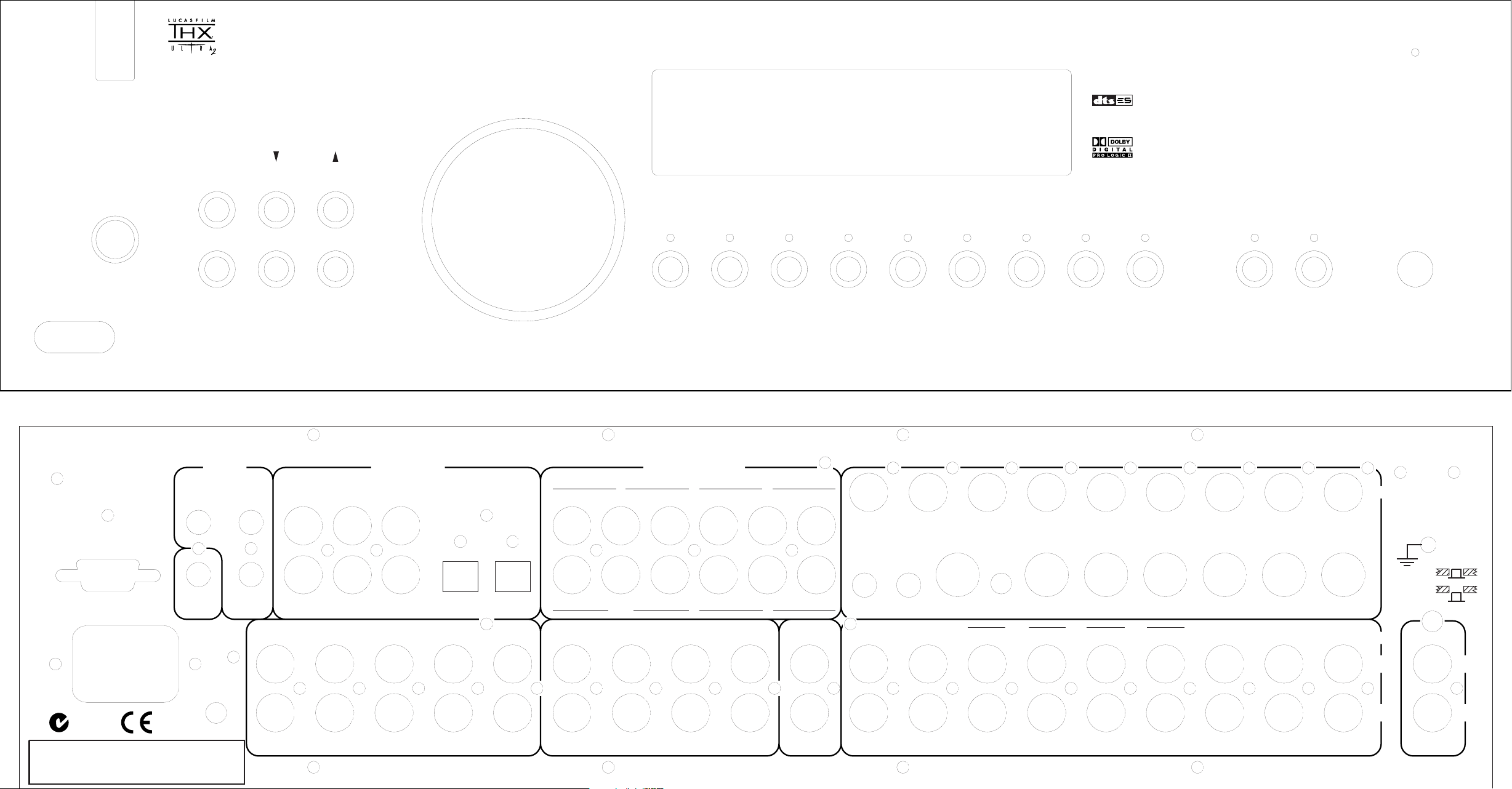
Front & rear view
diagram
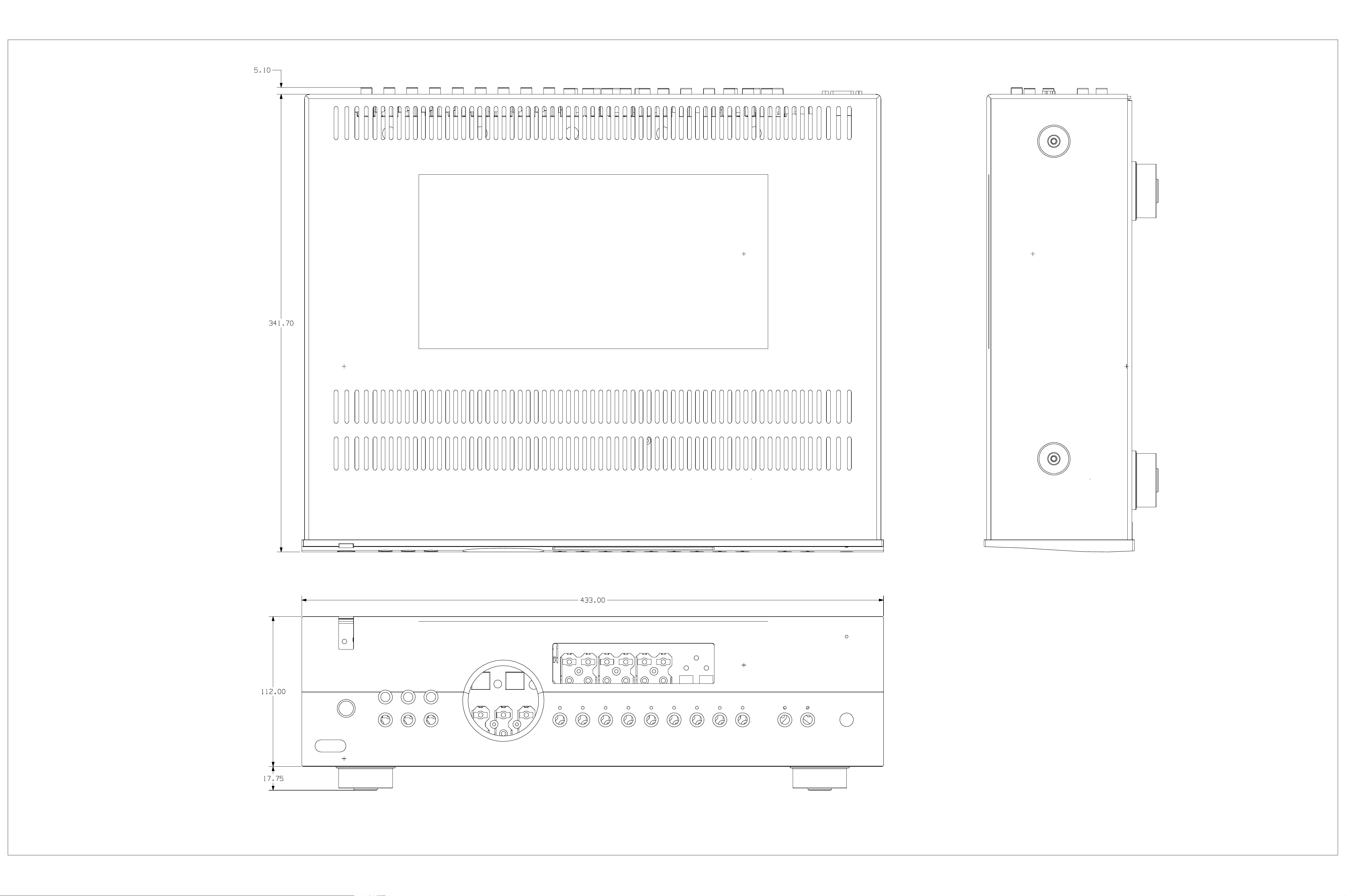
Dimensions diagram
Specifications
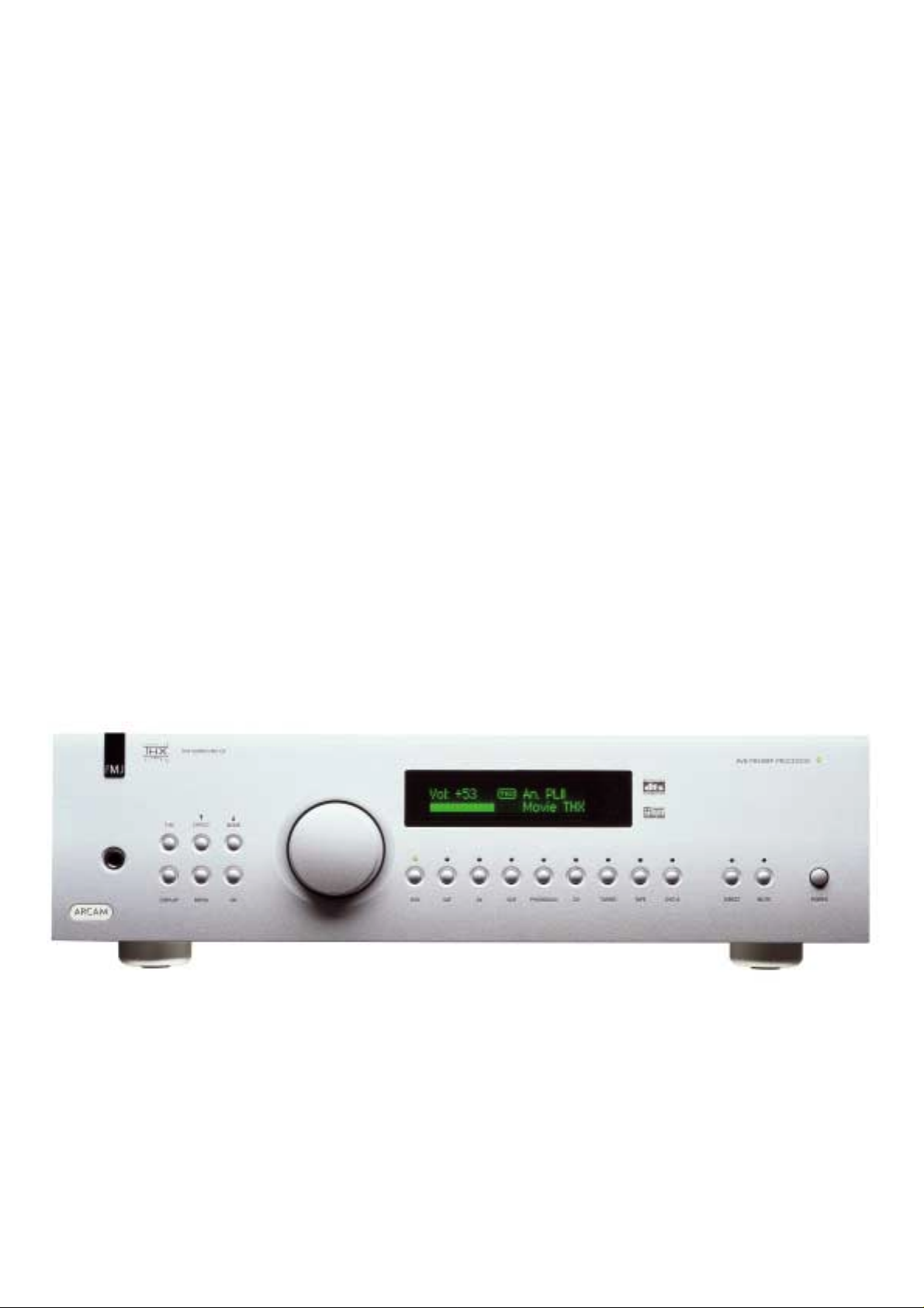
THX SURROUND EX
AV8 PREAMP PROCESSOR
MODEEFFECTTHX
DESIGNED & MADE
IN THE UK BY:A & R CAMBRIDGE,
WATERBEACH, CB5 9PB.
RS232
CONTROL
50/60Hz
100-240VAC
MAX 40VA
~
REMOTE DIGITAL INPUTS HIGH QUALITY VIDEO
1
U/B
U/B
OUT
V/R
V/R
OUT
12V
TRIGGER
IN
LOCAL
IN
ZONE 2
DVD
OUT
LEFT CENTRE SUB 2L SURR LS BACK LEFT CENTRE L SURR
AV
TUNER
TAPE
CD
VCR SAT
Y/G
Y/G
DVD-A MUTEDIRECTTAPETUNERCDPHONO/AUXVCRAVSATDVDOKMENUDISPLAY
Y/G
Y/G
2
U/B
U/B
3
LS BACK TUNER CD OUT IN OUT IN AV SAT DVD
V/R
V/R
ZONE 2
VIDEO
TRIGGERS
1/RGB 2/S-VIDEO
1
MONITOR OUT
2
TAPE
PROG
TAPE VCR
VCR
OUT
VCR
IN
AV SAT DVD
POWER
VIDEO
MM
MC
AUDIO
N1501
SERIAL No. LABEL
GROUND
LIFT (IN)
RIGHT SUB 1 SUB 3R SURR RS BACK RIGHT SUB R SURR
OUTPUTS DVD-A/SACD IN
WARNING: THIS APPLIANCE MUST BE EARTHED
ACHTUNG – VOR OEFFNEN DES GERAETES NETZSTECKER ZIEHEN. ATTENTION – RISQUE DE CHOC, NE PAS ENLEVER. PRECAUCION – PELIGRO DESCARGA, NO ABRIR.
RS BACK ZONE 2 OUT
L
R
L
R
AUX/
PHONO
L
R
CAUTION – SHOCK HAZARD, DO NOT OPEN.

Technical Specifications
Audio
Line input sensitivity (set to Reference) 2V rms
Input impedance 10k ohm
Preamp output level (nominal) 2V rms
Output impedance 25 ohm
Signal/noise ratio (unwtd 20Hz –20kHz)– analogue >100dB
Signal/noise ratio (unwtd 20Hz –20kHz)– digital (24-bit) >98dB
THD+N – analogue 0.0012%
THD+N – digital (24-bit) 0.0015%
Headphone maximum output level into 600 ohm 5V p-p
Output impedance 5 ohm
Video inputs and outputs
Input and output impedance 75 ohm
Composite video level 1V
HF response to (–3dB) 12MHz
S-video level (Y/C) 1V/0.28V
HF response to (–3dB) 12MHz
HQ (component) video
level (Y/Cr/Cb) 1V/0.5V/0.5V
level (R/G/B) 1V/1V/1V
HF response to (–3dB) 300MHz
Digital inputs
Coaxial connection (level/impedance) 0.5V/75 ohm
Acceptable sampling frequencies, all inputs 44.1kHz, 48kHz,
(96kHz stereo only)
Digital output
Output level/impedance 0.5V/75 ohm
Sampling frequency in ADC output mode 44.1kHz
Trigger outputs
Output D.C. voltage (excl. RGB status) 12V ±1V
Allowable load 30mA max (min 400 ohm)
Remote inputs and output
Signal modulated 36kHz carrier
Coding Philips RC-5
General
Mains voltage range 85V to 265V
Power consumption 35VA
Power consumption (standby) 32VA
Dimensions Width x Depth x Height (including feet) 433mm x 360mm x 130mm
Weight (net) 9kg
Weight (packed) 14kg
Supplied accessories Mains lead
CR80 remote control
2 x AAA batteries

Service Guide
Contents
!
!
!
Engineering mode
AV8 Programmer
software
AV8 Loader software

AV8 Engineering Mode
To access the software versions simultaneously press OK,
DVD & CD on the front panel.
The software versions will be displayed on the OSD.
AV8 Version: 2.0
THX Ul2: 13.0 DTS –ES: 15.0
Dolby D: 16.0 DTSNeo6: 18.0
Plogic 2 : 4.0 Cos Eff : 15.0
Exit this menu
Select EXIT and OK to leave the menu.
If no buttons have been pressed for 30 seconds the AV8
will automatically exit the menu.
Press THX, this takes you to the engineering menu first
page.
Use the up/down buttons on the front panel to select the
option followed by the volume control to adjust the
setting.
Engineering Menu
RC5 Code Zone 1 : 16* (or 19)
RC5 Code Zone 2 : 16* (or 19)
Scrolling Message: Off (or On)
Restore Defaults: No (or Yes)
Diagnostics : Off (or On)
Front Panel IR Rx : On (or Off)
EXIT
RC5 Code Zone 1
This allows you to select which RC5 system code zone 1
responds to (16 or 19). If set to code 19 the AV8 will not
respond to the CR 80 remote control.
RC5 Code Zone 2
This allows you to select which RC5 system code zone 2
responds to (16 or 19).
Scrolling Message
This allows you to turn the display scrolling message
on/off. When the messages are turn ed on you can select
the displa yed mess a ge by pressing t h e c orr esp on d in g i nput
button.
Button Message
DVD Arcam AV8 FMJ Home Theatre
SAT AV8 Multichannel Processor
AV arcam sideways
VCR Arcam AV8 Sound and Vision
AUX AV8 Designed in Cambridge UK
CD Arcam AV8 Preamp Processor
TUNER AV8 THX ULTRA 2, DTS ES, DOLBY PL2
Restore Defaults
This allows you to reset the AV8 to the factory default
settings.
Diagnostics (For factory diagnostics only)
This switches on RS232 messaging to allow remote
analysis (hyperterminal at 38400 baud, 8 data bits, no
parity, 1 stop bit and no flow control).
Please note tha t this will disable the R S232 interface for
user control via crest ron or similar controllers.
Front Panel IR Rx
This allows you to disable the front panel IR receiver and
prevent the AV8 f r o m respondin g to these signals.
With th e Engineering Menu title bar highlighted use the
volume control to select the second engineering page.
Engineering Menu 2
PLL Module
DVD : AUTO (or OFF)
SAT : AUTO (or OFF)
AV : AUTO (o r OFF)
VCR : AUTO (or OFF)
AUX : AUTO (or OFF)
CD : AUTO (or OFF)
TUNER :AUTO (or OFF)
TAPE : AUTO (or OFF)
EXIT
If the source equipment clock rates are operating outside
the specification of the AV8 phase locked loop circuit you
may experience “a hissing noise” from the audio outputs.
In this situation it is advisable to switch the phase locked
loop circuit off of th e input gi ving the problem. Using the
second page of th e engineering menu select the input and
turn the PLL (phase locked loop) from AUTO t o Off.
This can happen with Broadcast signa ls particularly from
satellite, cable or terrestrial digital TV.

AV8 Programmer
Future software up grades can be installed via the RS232
port on the back of the AV8. The following equipment will
be required:
! IBM PC compatible computer running Windows 98
or later
! Software – ARCAM AV8 Programmer utility
(included on the AV8 CD-ROM)
! Lead – RS232 9-way female D type to 9-way female
D type (null modem)
Installation procedure
The AV8 Programmer utility needs to be installed on your
PC before you can use it:
! Close down any programs which are running, then
insert the CD-RO M into the CD drive
! The setup program normally starts up automatically
when the disc is inserted. If this does not happen,
you can instruct the PC to install the program as
follows:
o Click on ‘Start’ and select ‘Run…’ from the
pop-up menu
o In the box, type ‘D:\setup.exe’, where ‘D’ is
your CD-ROM drive
o Click ‘OK’
The install process will then begin. You will be prompted
for your Name, Organization and Destination Folder for
the installation (default is C:\Program Files\Arcam\AV8
Programmer\). Follow the instructions on-s creen.
Operation procedure
! Open the AV8 Programmer utility by double clicking
the desktop icon, or from the Programs list within the
Start menu
! Switch off all the power amps connected to the AV8
! Switch off the AV8
! Connect th e RS232 lead from th e PC to the RS232
control port on the AV8
! From within the AV8 Progr ammer software:
o Select the new software file to be uploaded
using the ‘Open file’ button
o Select the Com port you are using
! Put the AV8 into program mode:
o Press and hold the program button on th e back
of the AV8 (located with the video output
connections)
o Turn the AV8 on with the progra m button still
pressed
o Wait 5 seconds and then release the program
button. The display will remain completely
blank and no LEDs will light.
! From within the AV8 Progr ammer software:
o Click ‘Program’
The PC will now upload the software and display the
following information:
Connecting: 0 to 100%
Programming: 0 to 100%
Verifying: 0 to 100%
This process will take up to four minutes. When the
software has been uploaded the message ‘Status:
SUCCESS’ will be displayed.
! Turn the AV8 off and unplug the RS232 lead
! Wait 10 seconds before turning the AV8 back on
If, after programming the AV8 the unit displays
“Populating EEPROM” when first turned on, it will be
necessary to reset the user configurations within the unit.
This is d ependent on the degree of the software c hanges
and will not always be necessary.
AV8 Loader (Preset Backup)
The AV8 Loader utility allows the unit settings to be either
downloaded from or uploaded to the AV8. The following
equipment will be required:
! IBM PC compatible computer running Windows 98
or later
! Software – ARCAM AV8 Loader utility (included
on the AV8 CD -ROM)
! Lead – RS232 9-way female D type to 9-way female
D type (null modem)
Installation procedure
The AV8 Loader utility can be run directly from the CDROM, or you can copy the entire ‘Preset Backup Utility’
folder to your ha rd dri ve (e.g. C:\ Progra m Files \ Arca m \
Preset Backup Utility).
Operation procedure
To run the AV8 Loader program:
! Connect th e RS232 lead from t he PC to the RS232
control connector on the AV8
! Switch off all the power amps connected to the AV8
! Run the AV8 Loader program:
o Click on ‘Start’ and select ‘Run…’ from the
pop-up menu
o In the box, type ‘D:\ Preset Backup Utility \
AV8Loader_GUI.exe’ or the location of the file
on the hard drive if no t using the CD-ROM
o Click ‘OK’
! Select the Com port you are using:
o Select ‘File -> Settings…’
o Select the Com port you are using from the
drop down menu
o Close the window
To download the settings from the AV8 to the PC:
! Create a new backup file:
o Select ‘File -> New…’
o Locate a suitable place to save the backup file
(e.g. C:\ Program Fi les \ Arcam \)
o Enter a name for the file in the ‘File name’ box
(e.g. AV8.epr). Note the ‘.epr’ name extension
o Click ‘Save’
! Download the AV8 s ettings:
o Select ‘Transfer -> Download From AV8…’
The AV8 Loader utility will then download the
configuration from the AV8 and save it using the filename
you gave. Once the setup is read from the AV8 it is
automatically stored as a “working file”.
To upload a configuration to the AV8 from the PC:
! Locate th e backup file you wish to upload:
o Select ‘File -> Open…’
o Locate the folder where the backup file is saved
o Select the name of the ‘.epr’ file you wish to
upload
o Click ‘Open’
! Upload the AV8 settings:
o Select ‘Transfer -> Upload To AV8…’
The AV8 automatically resets after the configuration has
been uploaded.

Build
Sequence
Contents
!
How to assemble the
AV8

1. Assemble the damping plate to chassis floor. Screw
through from underneath the chassis and thoroughly degrease the
chassis floor before assembling the damping plate. See FIG1.
Part No. Description Qty
E816CH Chassis 1
E873MC Damping Plate 1
HE6V06B Self-tapping No6x6mm Pan Torx-Slot
Steel Zinc-Plate Black
2. Assemble the feet to the chassis. Screw through the
chassis floor into the foot. Stick the bumpon foot onto the base of
turned foot. See FIG2.
Part No. Description Qty
E935MC Turned Foot 4
HA3V06A Screw Machine M3x6mm Pan Torx
Steel Zinc-Plate Clear
F225 Black ‘Bumpon’ Foot 4
3. Assemble the power socket to rear panel before
assembling the rear panel to the chassis. See FIG3.
Part No. Description Qty
E040AY Rear Panel Assembly 1
8A016 8A016 IEC Inlet with EMI Filter
YB10T1
HA3V10B Screw Machine M3x10mm Pan Torx-
Slot Steel Zinc-Plate Black
HJ3A00F Nut Nyloc M3 Steel Zinc-Plate Clear 2
HL3IB Washer Internal Shakeproof M 3 Steel
Zinc-Plate Black
4. Assemble power loom to IEC power inlet before
assembling the rear panel to the chassis. The live connection is
the right hand spade as viewed from behind (spade terminals)
with the earth spade at the top.
Part No. Description Qty
L939CA AV8 power loom 1
5. N.B. If a phono card is to be fitted then you do not fit
the “Aux” snap-off board at this stage, move to step 6. See step
23 for fitting the Phono upgrade kit.
Fit the “Aux” input snap-off board (snap-off from Audio board,
L921AY) to the rear panel before assembling the rear panel to the
chassis. See FIG4.
Part No. Description Qty
HF4V09B Screw Self-Tapping-SEMS No4x9mm
Pan Torx-Slot Steel Zinc-Plate Black
4
8
1
2
2
1
6. Assemble 5x H038 to audio board, L921AY, using 5x
HA3V06A in the holes running along the EMC can, only then fit
the board into the chassis with the other 5x H039 pillars (do no t fit
rear panel). Loosely screw all the pillars through the pcb into the
chassis, once these pillars are in place tighten them all.
See FIG5.
Part No. Description Qty
HF4V09B Screw Self-Tapping-SEMS No4x9mm
H038 38 ff pillars 5
H039 38 mf pillars 5
HA3V06A Screw Machine M3x6mm Pan Torx
HF4V09B Screw Self-Tapping-SEMS No4x9mm
NB. Screws in italics are to be used when rear pane l is fitted in
step 18.
7. Once the audio board is in place, fit the following
cables to the audio board. Ensure the cables, especially the flex
foil, are the correct way round.
Part No. Description Reference Qty
L925CA 8-way AMP CT from
L927CA 6-way AMP CT from
L930CA 5-way AMP CT from
L922CA 22-way foil cable from
L933CA 5-way AMP CT from
L923CA 8-way AMP CT from
L923CA 8-way AMP CT from
Pan Torx-Slot Steel Zinc-Plate Black
(into EMC shield)
Steel Zinc-Plate Clear (from
underneath)
Pan Torx-Slot Steel Zinc-Plate Black
(into sockets)
SK901 1
audio to snap-off 280mm
SK801 1
audio to horiz power
100mm
SK917 1
headphone to audio
250mm
SK916 1
digital to audio 100m m
SK915 1
digital to audio 100m m
SK913 1
digital to audio 120m m
SK914 1
digital to audio 120m m
3
5
19
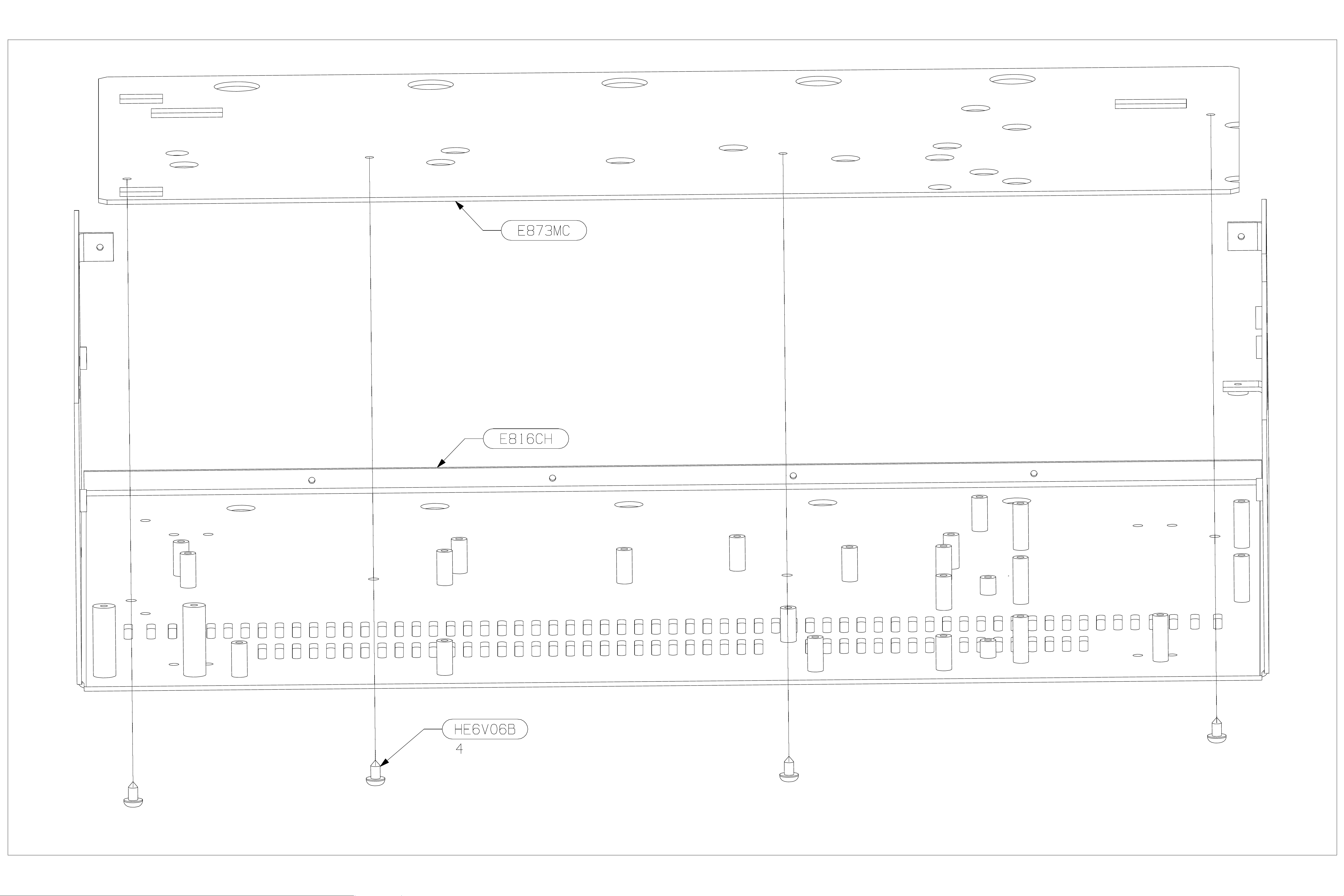
FIG1
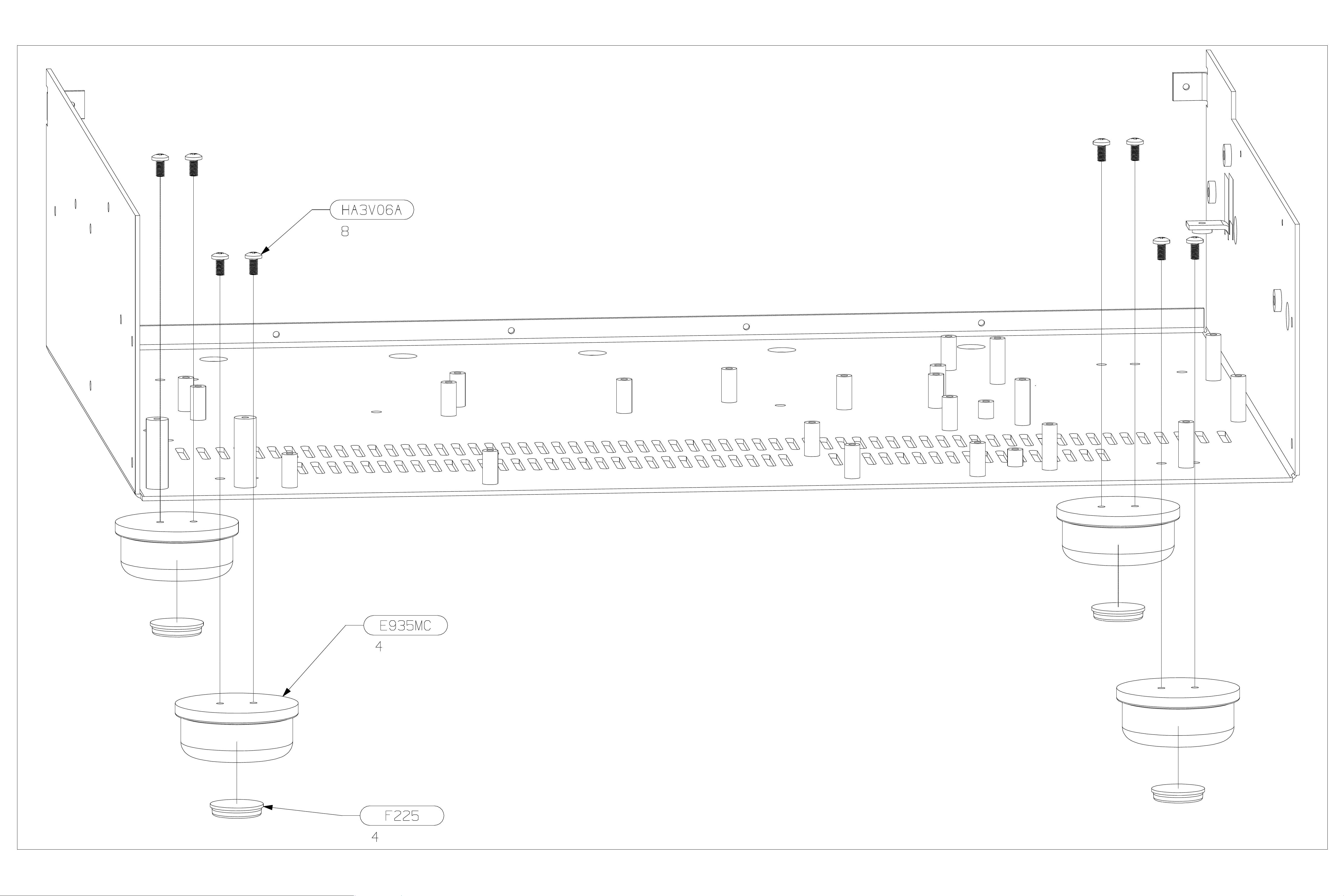
FIG2
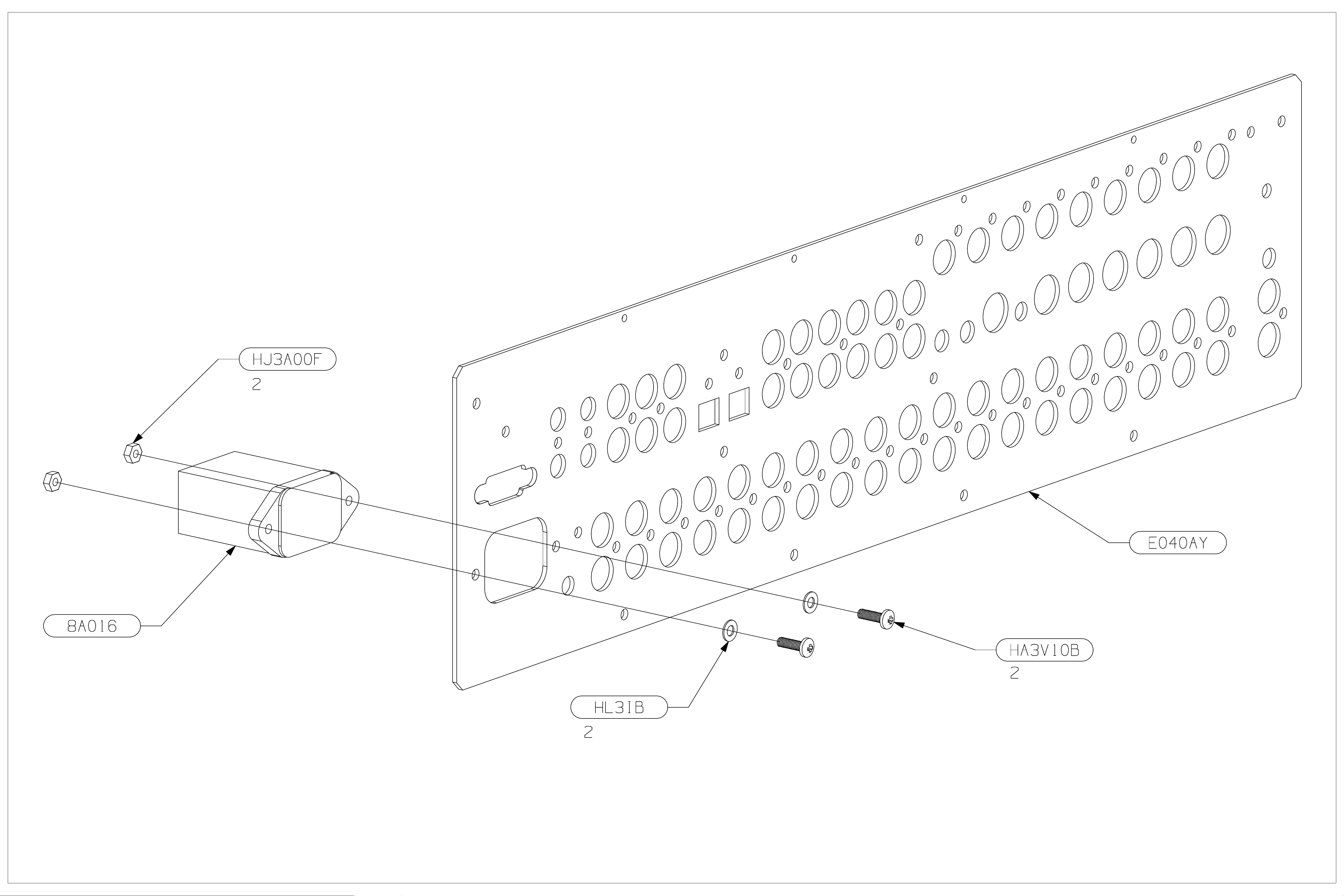
FIG3
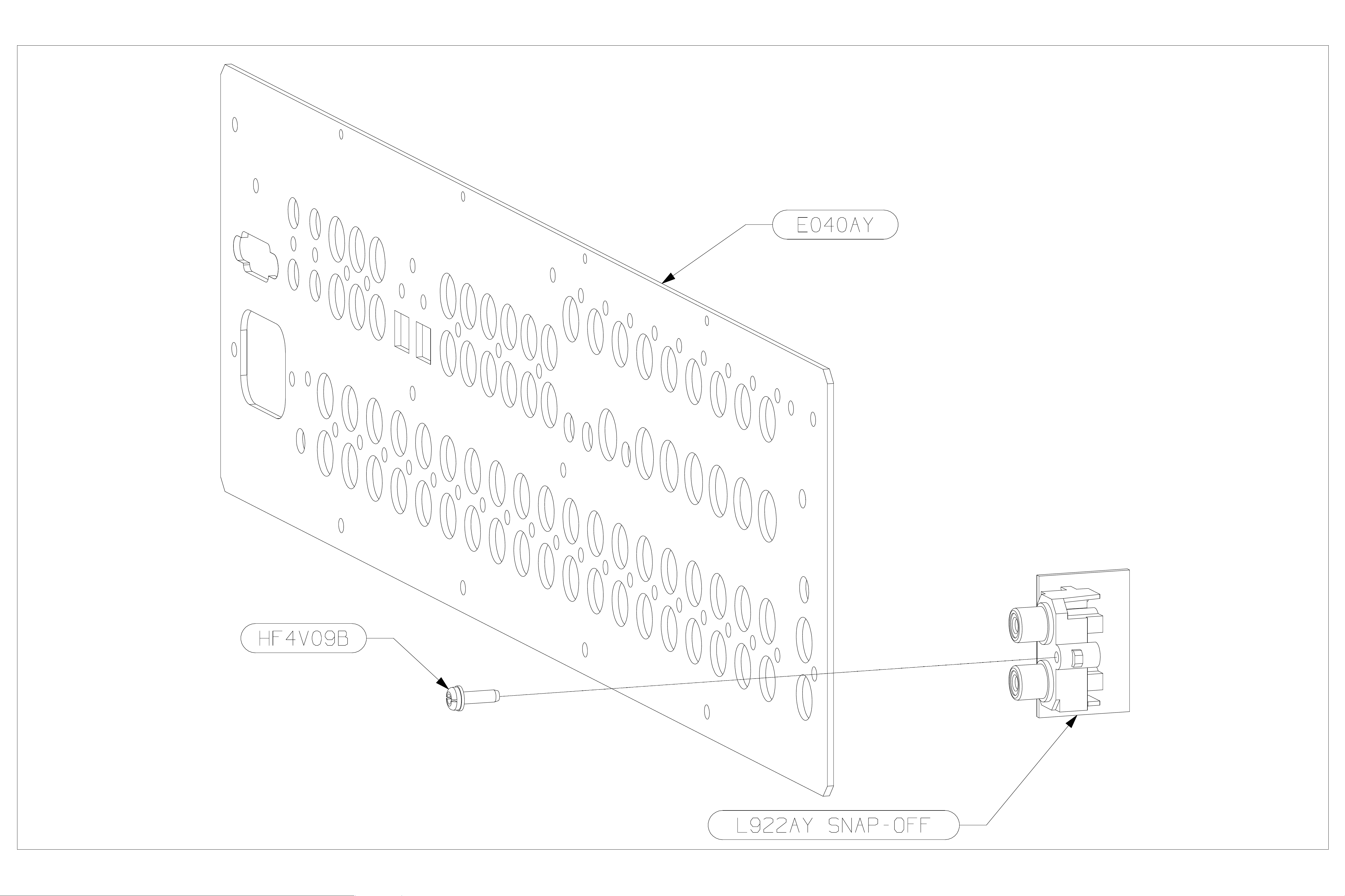
FIG4
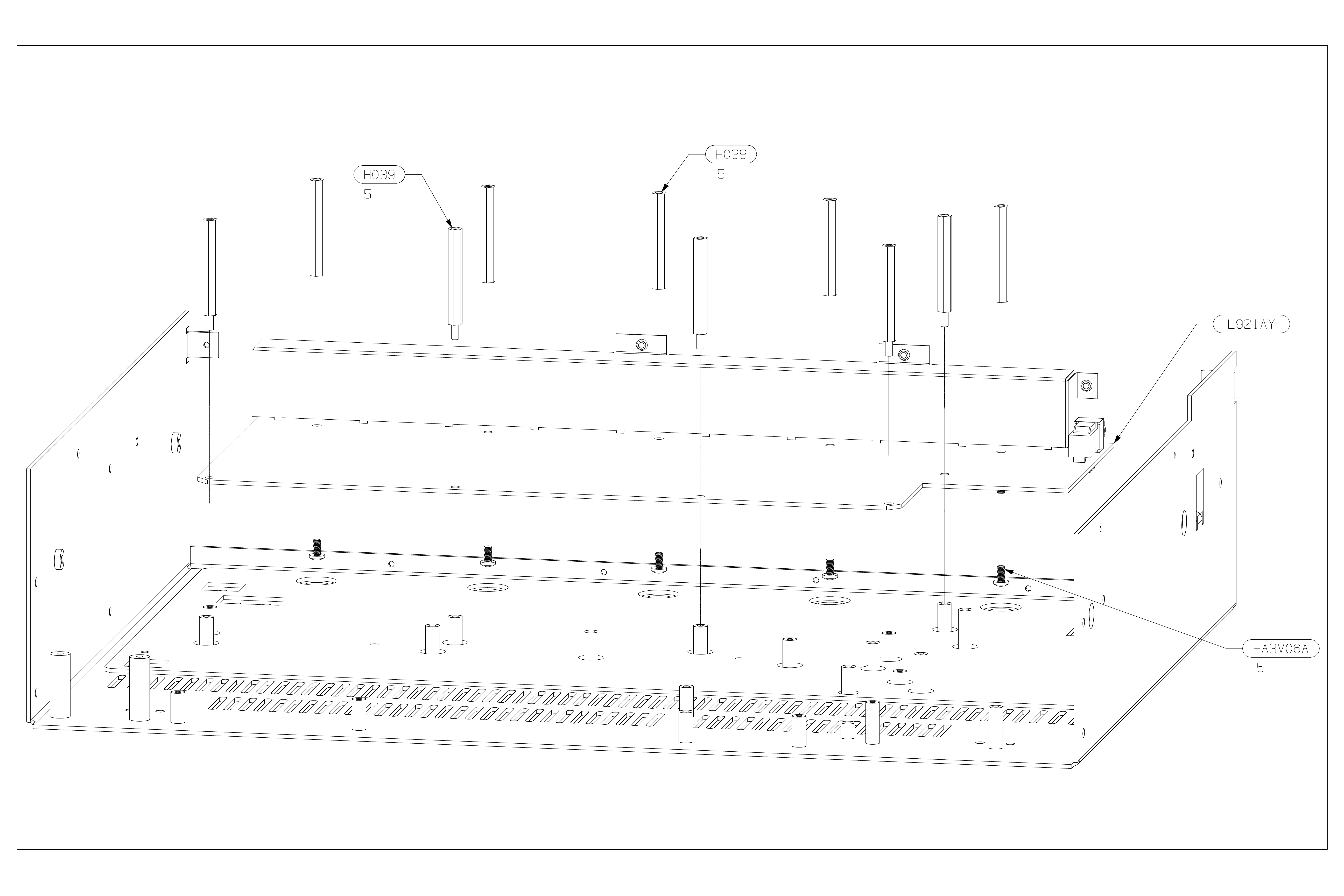
FIG5

8. Fit the video board (L922AY – main board) to the
chassis (do not fit rear panel yet). Ensure the board is pushed to
the back of the chassis before tightening down the board. Use
the H041 pillars in the two holes closest to the S-video
connectors (right hand side nearest the EMC screen as viewed
from the connector side). See FIG6.
Part No. Description Qty
HF4V09B Screw Self-Tapping-SEMS No4x9mm
H041 22 mf pillars 2
HA3V06A Screw Machine M3x6mm Pan Torx
HF4V09B Screw Self-Tapping-SEMS No4x9mm
cables to the video board:
Part No. Description Reference Qty
L922CA 22-way foil cable from
L925CA 8-way AMP CT from
L931CA 30-way foil cable from
9. Fit the top video board (L922AY – sub board) to
chassis (do not fit rear panel). See FIG7.
Part No. Description Qty
HF4V09B Screw Self-Tapping-SEMS No4x9mm
HA3V06A Screw Machine M3x6mm Pan Torx
HF4V09B Screw Self-Tapping-SEMS No4x9mm
Connect L922CA from the video board (SK700) to the top-video
board (SK209)
10. Fit the power can using 2x HA3V06A into standoffs.
See FIG8.
Part No. Description Qty
E876MC Power Can 1
HA3V06A Screw Machine M3x6mm Pan Torx
Pan Torx-Slot Steel Zinc-Plate Black
(into EMC shield)
Steel Zinc-Plate Clear thro’ video PCB
into standoffs
Pan Torx-Slot Steel Zinc-Plate Black
(thro’ RP into sockets)
Once the video board is in place, fit the following
SK700 1
top video to video
100mm
SK1000 1
video to horiz power
280mm
SK702 1
digital to video 190mm
Pan Torx-Slot Steel Zinc-Plate Black
(into EMC shield)
Steel Zinc-Plate Clear through top
video PCB into standoffs
Pan Torx-Slot Steel Zinc-Plate Black
(thro’ RP into sockets)
Steel Zinc-Plate Clear into s tandoffs
2
9
9
1
2
9
2
11. Fit the horizontal power PCB (L897AY – snap-off
part 2) using 6x HA3V06A screws into standoffs. Refer to FIG8.
Once the pcb is in place, fit the cables below.
Part No. Description Reference Qty
HA3V06A Screw Machine
M3x6mm Pan Torx
Steel Zinc-Plate Clear
into standoffs
L925CA 8-way AMP CT from
horiz power to digital
280mm
L926CA 7-way AMP CT from
horiz power to digital
350mm
L928CA 6-way AMP CT from
horiz power to digital
540mm
L925CA 8-way AMP CT from
horiz power to phase
lock loop 280m m
Connect the following cables using the reference table below:
Part No. From To
L927CA Audio / SK801 Horizontal power /
L925CA Video / SK1000 Horizontal power /
N.B. The Video cable L925CA has an excess of length so that the
video board may be removed but still remain connected when the
unit is serviced. A cable tie should be used to hold this excess
when the board is installed.
12. Fit the mains power button to the power switch, with
the button to the top. Refer to FIG8.
Part No. Description Qty
E887PM DiVA power button adapter 1
E850PM FMJ mains button (silver)
E850PMB FM J m ains button (black)
13. Fit the vertical power PCB. Once the pcb is in place,
fit the cable specified below.
Part No. Description Reference Qty
HA3V06A Screw Machine
M3x6mm Pan Torx
Steel Zinc-Plate Clear
into standoffs
L929CA 4-way AMP CT from
digital to vertical
power 220mm
14. Fit the headphone PCB (snap-off from video board).
Fit with socket facing to the front. Refer to FIG8.
Part No. Description Qty
HA3V06A Screw Machine M3x6mm Pan Torx
Steel Zinc-Plate Clear into s tandoffs
Connect L930CA from audio board (SK917) to the headphone
board (SKP1).
6
SK5 1
SK7 1
SK2 1
SK4 1
SK3
SK5
1
2
SK8 1
2
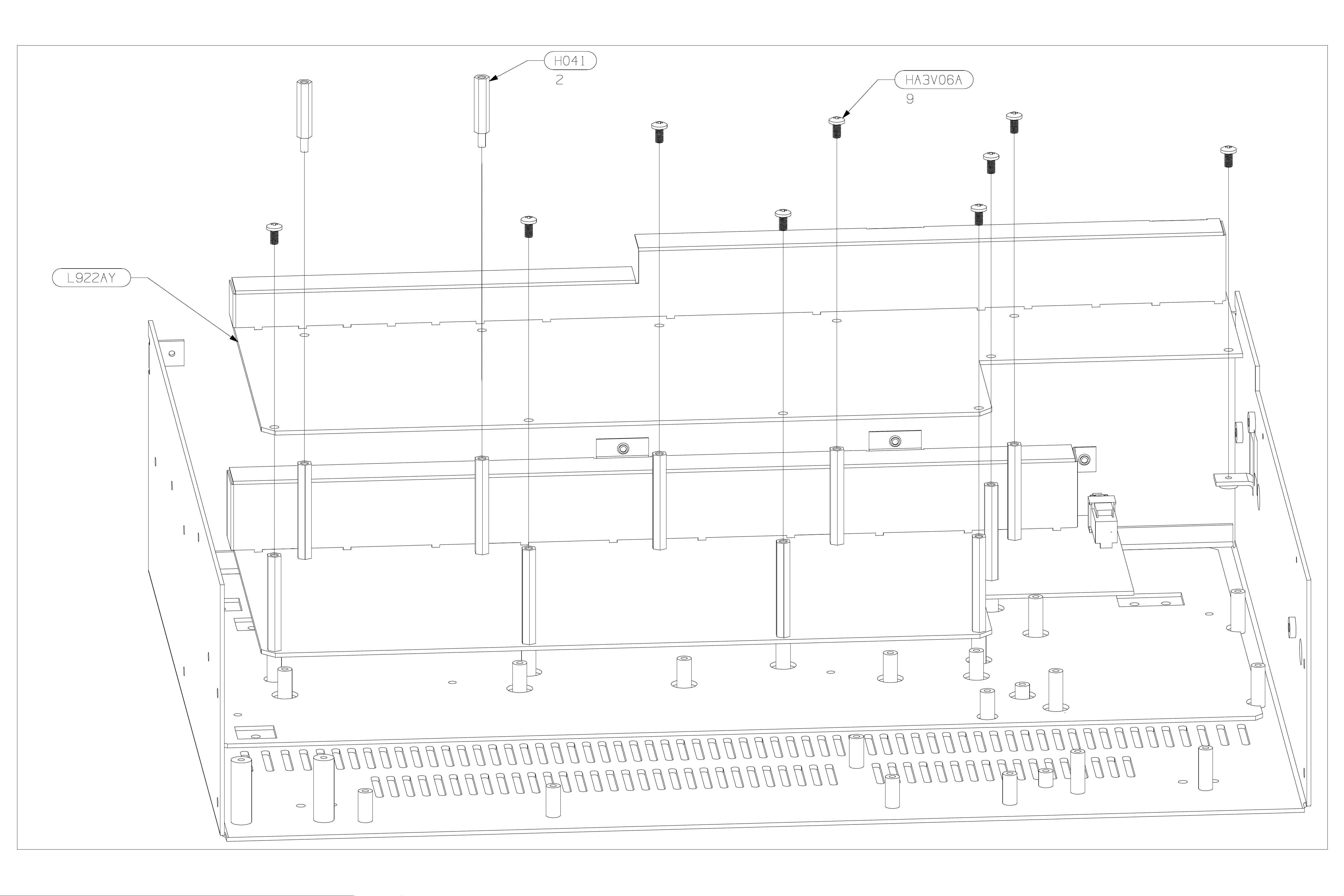
FIG6
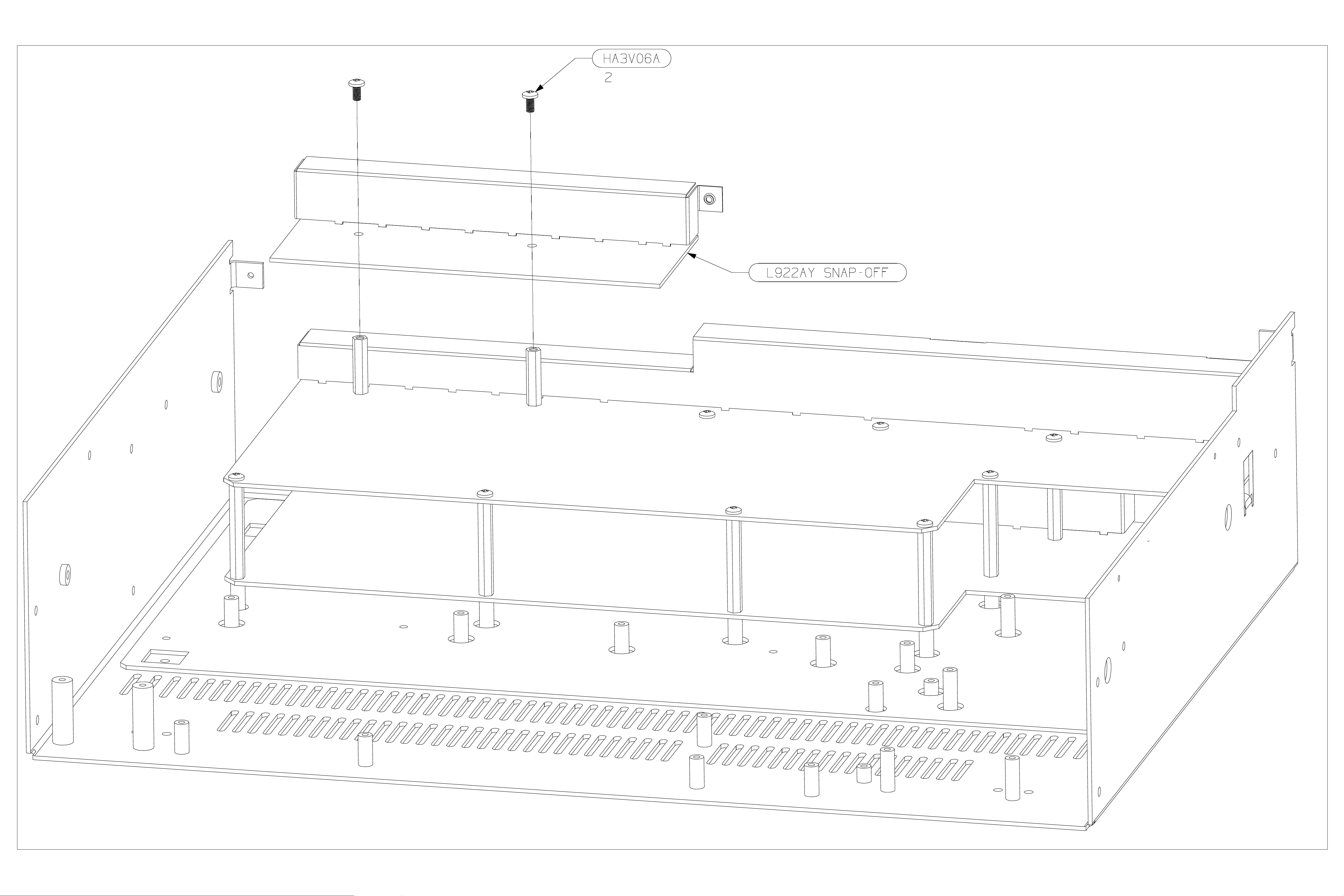
FIG7
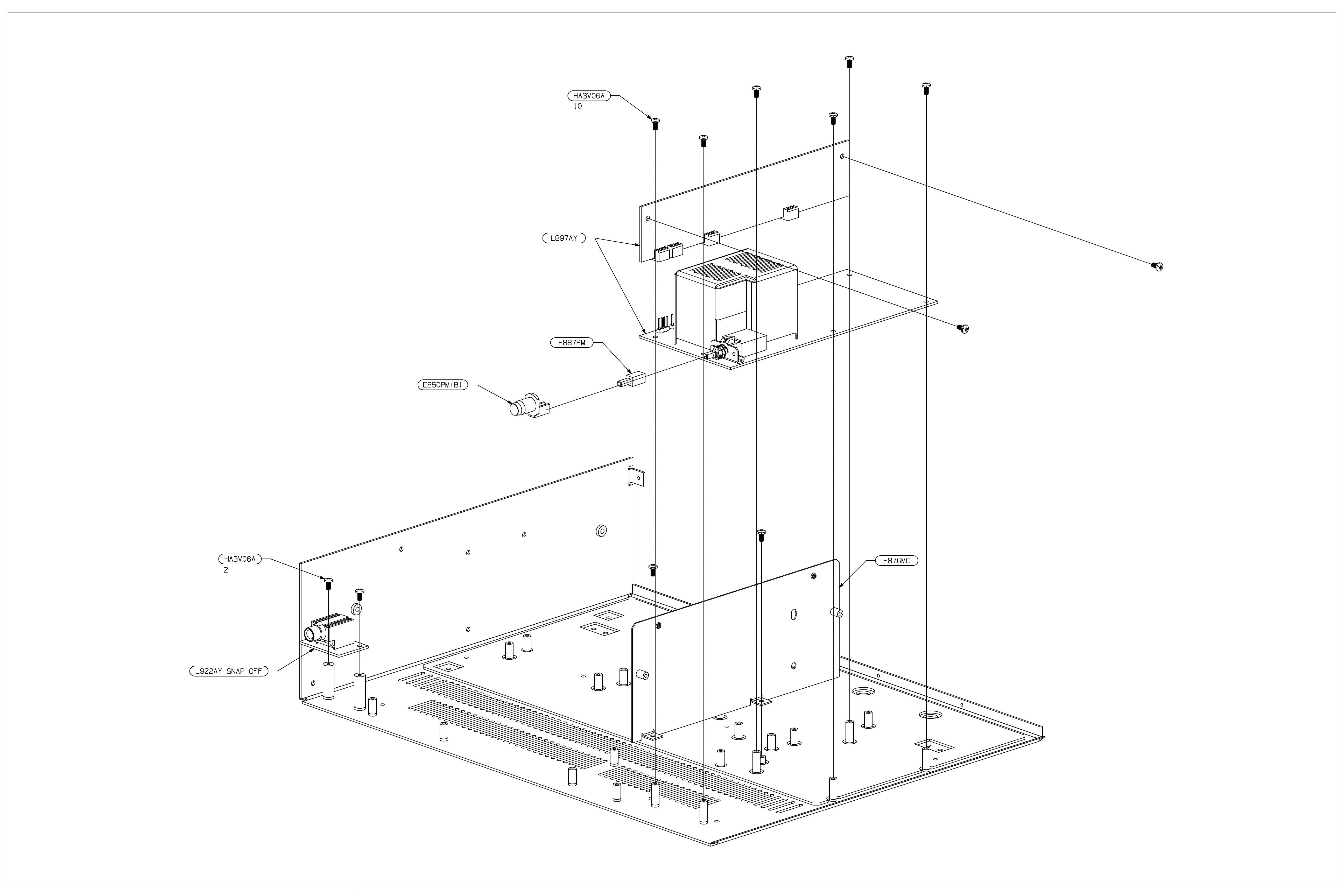
FIG8

15. Fit the digital PCB (L896AY) such that the notch in
the board is by the headphone board. Once the pcb is in place, fit
the cables below. See FIG9.
Part No. Description Reference Qty
H039 M3x38mm mf pillars
into standoffs
H030 M3x18mm mf pillars
into standoffs
L931CA 30-way foil cable from
digital to display 190mm
L923CA 8-way AMP CT from
digital to phase lock loop
120mm
L933CA 5-way AMP CT from
digital to phase lock loop
100mm
Connect the cable assemblies listed below.
Part No. From To
L923CA Audio / SK914 Digital / SK102
L923CA Audio / SK913 Digital / SK103
L933CA Audio / SK915 Digital / SK100
L922CA Audio / SK916 Digital / SK902
L931CA Video / SK702 Digital / SK900
L929CA Vertical Power / SK8 Digital / SK1002
L925CA Horizontal Power /
SK6
L926CA Horizontal Power /
SK7
L928CA Horizontal Power /
SK2
16. Fit the phase lock loop PCB (L948AY). See FIG9.
Part No. Description Qty
H030 M3x18mm mf pillars into standoffs 4
Connect the cable assemblies listed below.
Part No. From To
L923CA Digital / SK903 Phase lock loop / SK1
L933CA Digital / SK801 Phase lock loop / SK3
L925CA Horizontal Power /
SK4
17. Clip 2 F219 cable clips into top of EMC shield. Then
using the cable clips as handles fit EMC digital PCB shield.
Refer to FIG9.
Part No. Description Qty
E919MC Digital EMC Shield 1
HA3V06A Screw Machine M3x6mm Pan Torx
Steel Zinc-Plate Clear into s tandoffs
thro’ EMC shield into pillars
F219 Twist Lock cable clip 2
18. Assemble the rear panel to the chassis using all the
screws in italics on previous pages. Fit the power can lid over
the chassis and the vertical can wall with vents directly above the
EMC can on the power board. See FIG10.
Part No. Descrip tion Qty
HF4V09B Screw Self-Tapping-SEMS No4x9mm
Pan Torx-Slot Steel Zinc-Plate Black
(rear chassis return)
E877MC Power Can Lid 1
HF4V09B Screw Self-Tapping-SEMS No4x9mm
Pan Torx-Slot Steel Zinc-Plate Black
(2 into power can wall and 2 into
chassis wall)
7
4
SK901 1
SK903 1
SK801 1
Digital / SK1001
Digital / SK1003
Digital / SK1000
Phase lock loop / SK2
11
6
4
Connect the cable assemblies listed below.
Part No. From To
L939CA IEC Inlet Horizontal Power /
L925CA Audio / SK901 Aux snap-off / SK927
19. Assemble the phono can assembly to the chassis (3
screws) and the rear panel (1 screw) making sure the cable loom
fits into notch in top of the phono can. See FIG11.
Part No. Description Qty
E041AY Phono Can Assembly 1
HF4V09B Screw Self-Tapping-SEMS
20. Assemble the display PCB to the fascia assembly
Part No. Description Qty
E919AY Fascia Assembly (silver)
E919AYB Fascia Assembly (black)
HA3V06A Screw Machine M 3x6m m Pan Torx
21. Assemble the fascia assembly and the display PCB to
the chassis. Check the operation of mains button at this stage.
Keep the foil bent upwards. Connect the flexfoil after the fascia
assembly is fitted to the chassis.
Part No. Description Qty
HE6V06B Self Tapping No6x6mm Pan Torx-
Connect L931CA from the digital board (SK901) to the display
board (SK100).
22. Assemble the cover plate to the chassis
Part No. Description Qty
E826CP Cover Plate (Silver)
E826CPB Cover Plate (black)
HA4V06S
HA4V06B Screw Machine M4x6mm Pan Torx
HF4V09B Screw Self-Tapping-SEMS
23. Fit the Phono Board Upgrade Kit, using L870AY
board and the following parts. See FIG12 for assembly
instructions.
Part No. Descrip tion Qty
H031 20 ff pillars 3
HF4V09B Screw Self-Tapping-SEMS
HA3V06A Screw Machine M3x6mm Pan Torx
No4x9mm Pan Torx-Slot Steel
Zinc-Plate Black
Steel Zinc-Plate Clear into s tandoffs
Slot Steel Zinc-Plate Black
Screw Machine M4x6mm Pan Torx
St Steel Nickel
St Steel Black
No4x9mm Pan Torx-Slot Steel
Zinc-Plate Black
No4x9mm Pan Torx-Slot Steel ZincPlate Black into rear panel
Steel Zinc-Plate Clear into pillars
8-way AMP CT from phono (SK2) to
audio (SK901) 280mm
8-way connector 2
SK1
4
1
14
4
1
4
4
1
6
1 L925CA
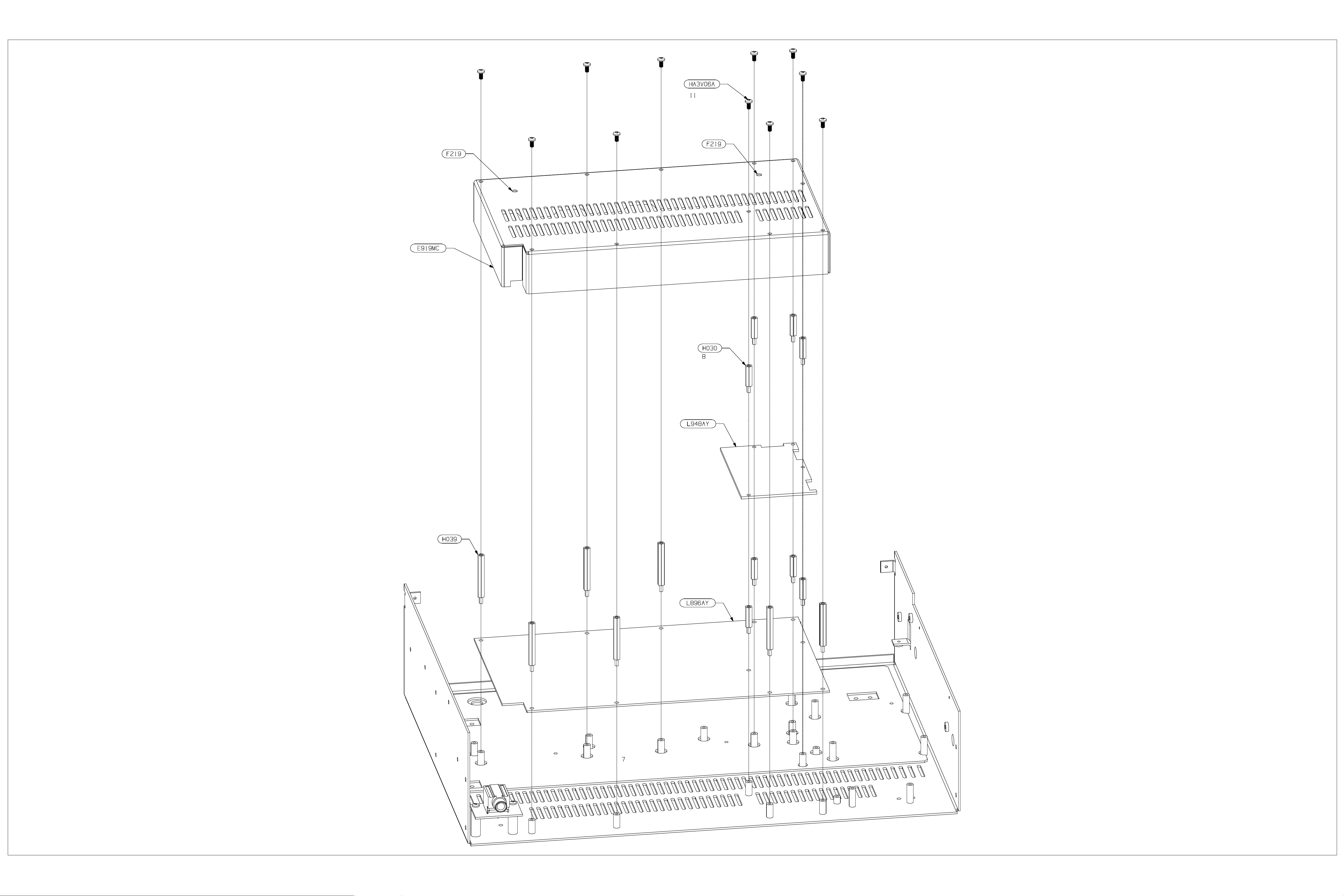
FIG9
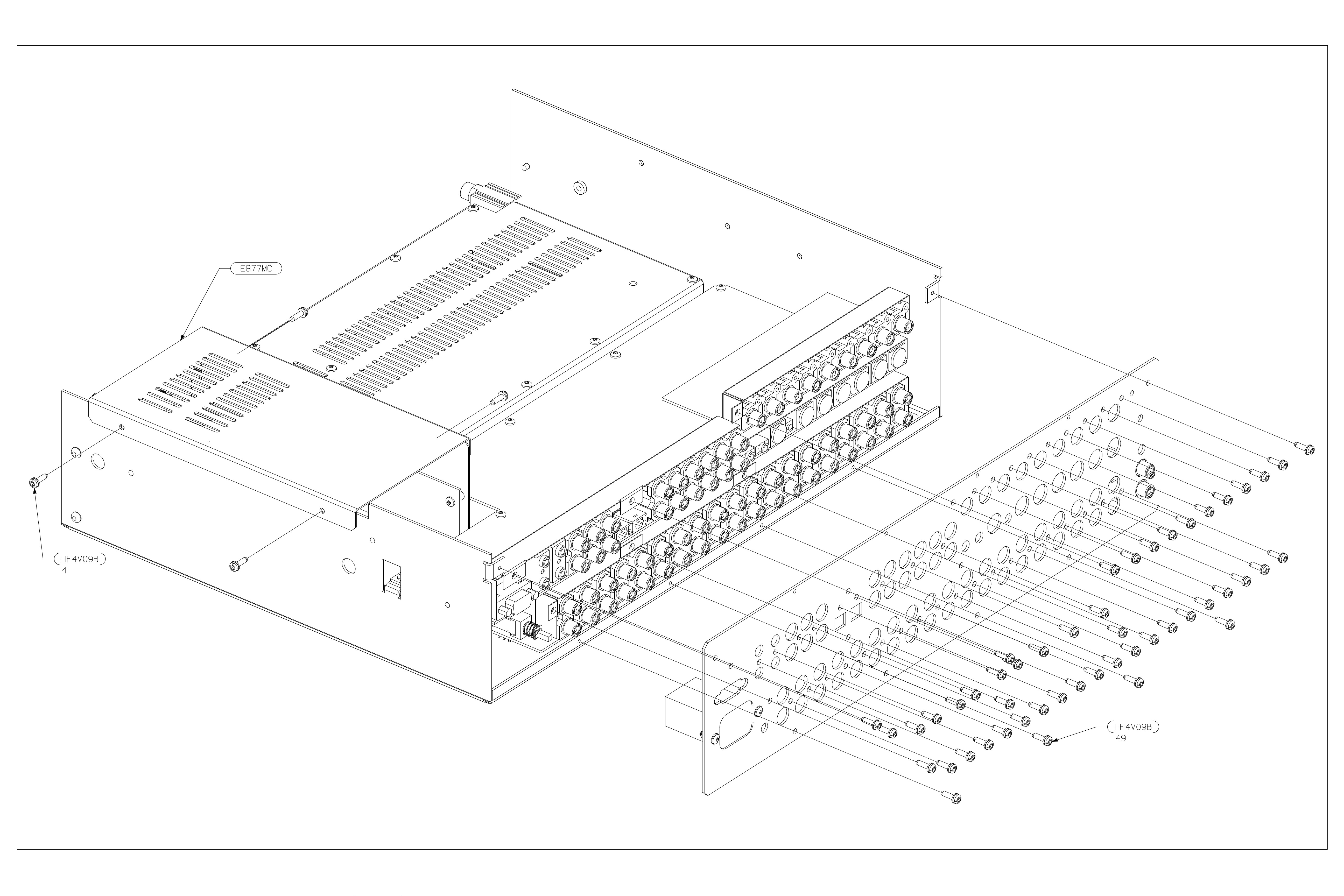
FIG10
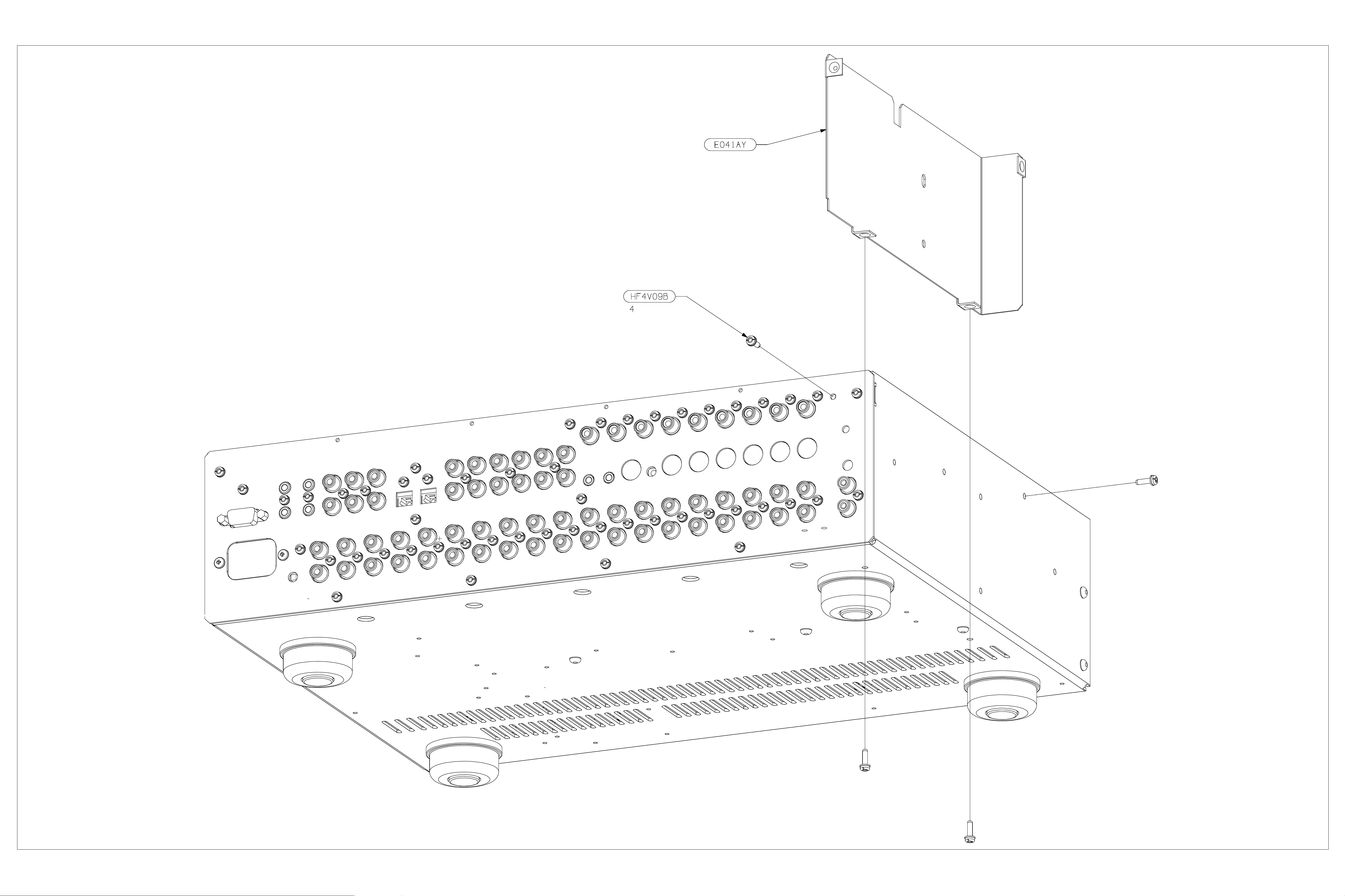
FIG11
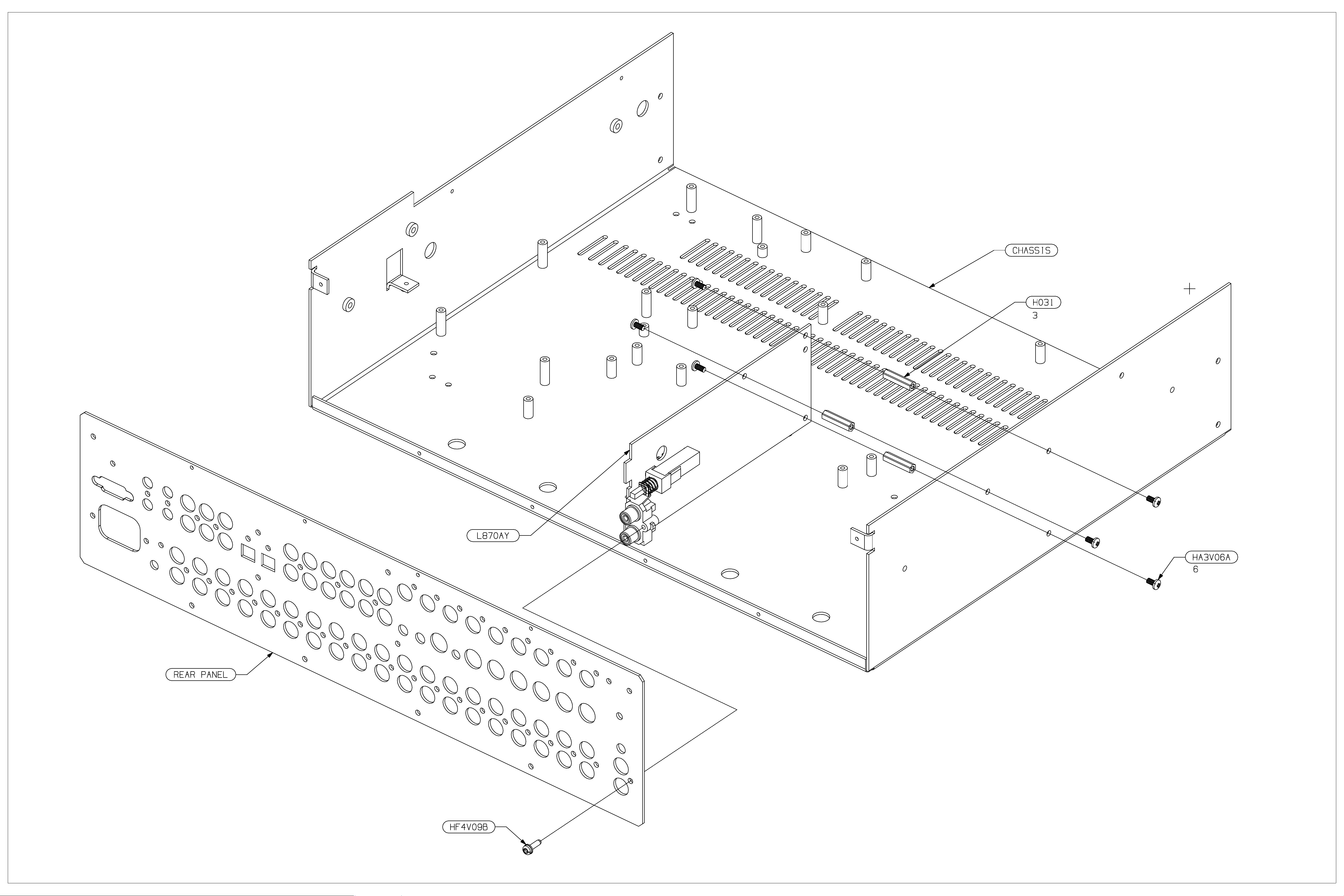
FIG12

Phono
Board
L870
Contents
!
Circuit description
!
Component overlay
!
Parts list
!
Circuit diagrams

AV8 Phono Board
Circuit Description
Refer to circuit diagram L870 sheet 1
The phono board is a simple single stage RIAA amplifier
and consists of two channels of high gain amplification,
and the ability to switch between moving magnet (MM)
and moving coil (M C) settings.
PSU
The unit derives its +
fitted into with only local decoupling capacitors on board.
Interface
The unit connects to the host unit via a 8 way connector.
Amplification
The left channel h as designators beginnin g with 100, and
the right with 200. For the purposes of this description the
left channel will be described, as the right channel is the
same in all respects.
The amplifier is a small signal class A voltage feedback
amplifier with switch able gain. The input consists of an
actively loaded differential pair of very low noise PNP
transistors (TR106, TR107). These transistors are very
specific and should only be replaced with identical parts
with the E grade high gain. TR100 and TR101 form a
current source for the pair, which sets the qu iescent current
for the entire amplifier. The active load consists of TR110
and TR111, which forms part of the differential current
mirror with TR112, TR113 & TR114. This differential
stage also h as an active load (TR102 & TR10 3) to keep
gain to a maximum.
Both of these di fferential stages are design ed to have as
much gain as p ossible to enable the sing le stage design.
The RIAA respon se is achieved in th e feedback network:
C101, C110, C111, C112, C119, C120 and R115, R112.
C115 is used to correct between MM and MC gains as the
amplifier is non-inverting.
SW100 switches between MM and MC. Two poles of the
switch change between the different loading required for
each type of the cartridge: R108 & C109 for MM and
added in parallel for MC R104 & C108. The other two
poles chan ge the feedbac k resister valu e to alter th e gain:
R105 for MM and added in parallel for MC R123.
The DC offset is c ontrolled by a non-i nverting s ervo built
around IC100. The amount of servo current is different for
each gain setting via R111 (MM) and R124 (MC) so that
the low frequency high pass point remains the same for
both settings. However the high pass point for the circuit
is set by C113. This gives a warp filter, stops DC start-up
thumps from upsetting DC coupled circuitry and an
approximation of the RIAA/IEC curve (-2dB @ 20Hz)
The output is class A buffered by a d ual mirror follower
(TR104, TR105, TR108, TR109). The quiescent current is
set by D100 and R118 and R119.
Closed loop st ability is achieved with C16, C117, gi ving
symmetrical slewing capability.
15V regulated rails from the unit it is
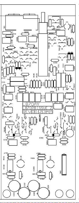

L870 Phono Board Parts List Issue 2.0
Designator Part Description
C1 2A410 CERD 100N 63V -20% +80% RA
C100 2N622 ELST 22U 63V
C101 2D210 PPRO 1N0 5% 63V RA
C102 2P710AS ELEC 100U 25V SILMIC
C103 2P710AS ELEC 100U 25V SILMIC
C104 2K410 PEST 100N 63V 10%
C105 2K410 PEST 100N 63V 10%
C106 2K410 PEST 100N 63V 10%
C107 2K410 PEST 100N 63V 10%
C108 2D147W PPRO W 470P 63V 5% RA
C109 2D110W PPRO W 100P 63V 5% RA
C110 2D247N PPRO 4N7 63V 5% RA
C111 2D310 PPRO 10N 63V 1% AXIAL
C112 2D310 PPRO 10N 63V 1% AXIAL
C113 2K510 CAP MKS2 1U0 16V 10%
C115 2D213N PPRO 1N3 63V 5% RA
C116 2D147W PPRO W 470P 63V 5% RA
C117 2D147W PPRO W 470P 63V 5% RA
C118 2U610 ELST NON POLAR 10UF 35V
C119 2D110N PPRO 100P 63V 5% RA
C120 2D210 PPRO 1N0 5% 63V RA
C200 2N622 ELST 22U 63V
C201 2D210 PPRO 1N0 5% 63V RA
C202 2P710AS ELEC 100U 25V SILMIC
C203 2P710AS ELEC 100U 25V SILMIC
C204 2K410 PEST 100N 63V 10%
C205 2K410 PEST 100N 63V 10%
C206 2K410 PEST 100N 63V 10%
C207 2K410 PEST 100N 63V 10%
C208 2D147W PPRO W 470P 63V 5% RA
C209 2D110W PPRO W 100P 63V 5% RA
C210 2D247N PPRO 4N7 63V 5% RA
C211 2D310 PPRO 10N 63V 1% AXIAL
C212 2D310 PPRO 10N 63V 1% AXIAL
C213 2K510 CAP MKS2 1U0 16V 10%
C215 2D213N PPRO 1N3 63V 5% RA
C216 2D147W PPRO W 470P 63V 5% RA
C217 2D147W PPRO W 470P 63V 5% RA
C218 2U610 ELST NON POLAR 10UF 35V
C219 2D110N PPRO 100P 63V 5% RA
C220 2D210 PPRO 1N0 5% 63V RA
D100 3A4148 SSDIODE 1N4148 75V
D101 3A4148 SSDIODE 1N4148 75V
D102 3A4148 SSDIODE 1N4148 75V
D200 3A4148 SSDIODE 1N4148 75V
D201 3A4148 SSDIODE 1N4148 75V
D202 3A4148 SSDIODE 1N4148 75V
IC100 5B071 IC FET OPAMP TL071
IC200 5B071 IC FET OPAMP TL071
PCB1 L870PB_2 PRINTED CIRCUIT BOARD
R100 1H133 RES MF W4 1% 330R
R101 1H110 RES MF W4 1% 100R
R102 1H110 RES MF W4 1% 100R
R104 1H110 RES MF W4 1% 100R
R105 1H110 RES MF W4 1% 100R
R106 1H110 RES MF W4 1% 100R
R108 1H347 RES MF W4 1% 47K
R109 1H312 RES MF W4 1% 12K
R110 1H312 RES MF W4 1% 12K
R111 1H356 RES MF W4 1% 56K
R112 1H410 RES MF W4 1% 100K
R113 1H410 RES MF W4 1% 100K
R114 1H410 RES MF W4 1% 100K
R115 1H315 RES MF W4 1% 15K
R116 1H522 RES MF W4 1% 2M2
 Loading...