


Arcam FMJ AV-8 Owners manual

AV8 Preamp Processor
Préamplificateur-processeur AV8
Vorverstärker/Prozessor AV8
AV8 Voorversterker Processor
E-2
E-2
E-3
English
Safety guidelines
CAUTION: To reduce the risk of electric shock, do not remove cover
(or back). No user serviceable parts inside. Refer servicing to qualified
service personnel.
WARNING: To reduce the risk of fire or electric shock, do not expose
this apparatus to rain or moisture.
The lightning flash with an arrowhead symbol within an equilateral
triangle, is intended to alert the user to the presence of uninsulated
‘dangerous voltage’ within the product’s enclosure that may be of
sufficient magnitude to constitute a risk of electric shock to persons.
The exclamation point within an equilateral triangle is intended to alert
the user to the presence of important operating and maintenance
(servicing) instructions in the literature accompanying the product.
CAUTION: In Canada and the USA, to prevent electric shock, match
the wide blade of the plug to the wide slot in the socket and insert the
plug fully into the socket.
IMPORTANT SAFETY INSTRUCTIONS
This product is designed and manufactured to meet strict quality
and safety standards. However, you should be aware of the following
installation and operation precautions:
1. Take heed of warnings and instructions
You should read all the safety and operating instructions before
operating this appliance. Retain this handbook for future reference and
adhere to all warnings in the handbook or on the appliance.
2. Water and moisture
The presence of electricity near water can be dangerous. Do not use
the appliance near water – for example next to a bathtub, washbowl,
kitchen sink, in a wet basement or near a swimming pool, etc.
3. Object or liquid entry
Take care that objects do not fall and liquids are not spilled into the
enclosure through any openings. Liquid filled objects such as vases
should not be placed on the equipment.
4. Ventilation
Do not place the equipment on a bed, sofa, rug or similar soft surface, or
in an enclosed bookcase or cabinet, since ventilation may be impeded.
We recommend a minimum distance of 50mm (2 inches) around the
sides and top of the appliance to provide adequate ventilation.
5. Heat
Locate the appliance away from naked flames or heat producing
equipment such as radiators, stoves or other appliances (including
other amplifiers) that produce heat.
6. Climate
The appliance has been designed for use in moderate climates.
7. Racks and stands
Only use a rack or stand that is recommended for use with audio
equipment. If the equipment is on a portable rack it should be moved
with great care, to avoid overturning the combination.
8. Cleaning
Unplug the unit from the mains supply before cleaning.
The case should normally only require a wipe with a soft, damp, lint-
free cloth. Do not use paint thinners or other chemical solvents for
cleaning.
We do not advise the use of furniture cleaning sprays or polishes as
they can cause indelible white marks if the unit is subsequently wiped
with a damp cloth.
9. Power sources
Only connect the appliance to a power supply of the type described in
the operating instructions or as marked on the appliance.
10. Power-cord protection
Power supply cords should be routed so that they are not likely to be
walked on or pinched by items placed upon or against them, paying
particular attention to cords and plugs, and the point where they exit
from the appliance.
11. Grounding
Ensure that the grounding means of the appliance is not defeated.
12. Power lines
Locate any outdoor antenna/aerial away from power lines.
13. Non-use periods
If the unit has a standby function, a small amount of current will continue
to flow into the equipment in this mode. Unplug the power cord of the
appliance from the outlet if left unused for a long period of time.
14. Abnormal smell
If an abnormal smell or smoke is detected from the appliance, turn
the power off immediately and unplug the unit from the wall outlet.
Contact your dealer immediately.
15. Servicing
You should not attempt to service the appliance beyond that described
in this handbook. All other servicing should be referred to qualified
service personnel.
16. Damage requiring service
The appliance should be serviced by qualified service personnel when:
A. the power-supply cord or the plug has been damaged, or
B. objects have fallen, or liquid has spilled into the appliance, or
C. the appliance has been exposed to rain, or
D. the appliance does not appear to operate normally or exhibits a
marked change in performance, or
E. the appliance has been dropped or the enclosure damaged.
SAFETY COMPLIANCE
This product has been designed to meet the IEC 60065 international
electrical safety standard.
RISQUE DE CHOC ELECTRIQUE
NE PAS OUVRIR
ATTENTION
CAUTION
RISK OF ELECTRIC
SHOCK DO NOT OPEN

E-3
English
Welcome to the AV8 Preamp Processor
USING THIS HANDBOOK
Thank you for purchasing the Arcam FMJ AV8 Preamp Processor.
This handbook has been designed to give you all the information you
need to install, connect, set up and use the Arcam FMJ AV8 Preamp
Processor. The remote control handset supplied with the equipment
is also described.
It may be that the AV8 has been installed and set up as part of your
Hi-Fi installation by a qualified Arcam dealer. In this case, you may wish
to skip the sections of this handbook dealing with installation and
setting up the unit. Use the Contents list to guide you to the relevant
sections.
SAFETY
Safety guidelines are set out on page two of this handbook.
Many of these items are common sense precautions, but for your own
safety, and to ensure that you do not damage the unit, we strongly
recommend that you read them. This is a class 1 product and requires
an earth connection.
INTRODUCTION
The AV8 is a high quality and high performance home cinema
processor and audio pre-amplifier built to Arcam’s traditional high
quality design and manufacturing standards. It combines high resolution
digital processing with high performance audio and video components
to bring you an unrivalled home entertainment centre.
The AV8 allows quality switching and volume control of eight analogue
and seven digital sources making it an ideal companion for both home
cinema and two-channel stereo systems. Since many of these source
components are also capable of outputting high quality video signals,
the AV8 includes broadcast quality video switching for composite, Svideo, component and RGB video signals. There are inputs and outputs
for both tape and VCR, as well as a digital output. DVD-Audio and
SACD can be connected via the multichannel input. Control of the AV8
is either by front panel control buttons, IR remote control or an RS232
port (which can be used to upload future software enhancements).
On the back panel there are trigger outputs for easy connection to
associated equipment. The AV8 can easily be integrated with various
types of power amplifiers and loudspeakers, including those that are
THX certified. The AV8 is itself THX certified, meaning it has passed
the rigorous THX Ultra2 specification enabling it to reproduce THX
Surround EX signals from Dolby Digital soundtracks.
The customised installation of the AV8 in a listening room is an
important process which requires care at every stage. For this reason,
the installation information is very comprehensive and should be
followed carefully.
The AV8 has a universal input power supply that is compatible with
mains voltages between 85V AC and 265V AC, 50Hz to 60Hz.
Manufactured under licence from Dolby Laboratories, Inc.
‘Dolby’, ‘Pro Logic’, ‘Surround EX’ and the double-D symbol are trademarks of Dolby
Laboratories.
Copyright © 1992–1999 Dolby Laboratories, Inc. All rights reserved.
Manufactured under license from Digital Theater Systems, Inc. US Pat. No. 5,451,942,
5,956,674, 5,974,380, 5,978,762 and other world-wide patents issued and pending.
“DTS”, “DTS-ES Extended Surround” and “Neo:6” are trademarks of Digital Theater
Systems, Inc.
Copyright © 1996, 2000 Digital Theater Systems, Inc. All Rights Reserved.
Lucasfilm and THX are trademarks or registered trademarks of Lucasfilm, Ltd.
Copyright © Lucasfilm Ltd. &TM.
Surround EX is a jointly developed technology of THX and Dolby Laboratories, Inc. and is a
trademark of Dolby Laboratories, Inc. All rights reserved. Used under authorization.
CONTENTS
Safety guidelines..........................................................................E-2
Safety instructions ..............................................................................E-2
Safety compliance...............................................................................E-2
Welcome to the AV8 Preamp Processor..............................E-3
Installation ....................................................................................E-4
Positioning the unit............................................................................E-4
Notes about connections..............................................................E-4
Cables........................................................................................................E-5
Speaker Installation............................................................................E-5
Audio connections.............................................................................E-6
Zone 2 connections..........................................................................E-7
Video connections.............................................................................E-7
Control connections.........................................................................E-8
Trigger outputs.....................................................................................E-8
Connecting to a power supply...................................................E-9
Conguring the AV8 ...............................................................E-10
Basic Setup ..........................................................................................E-11
Advanced Setup...............................................................................E-14
Front panel controls ...............................................................E-17
Remote control........................................................................ E-18
Operating your AV8 ................................................................ E-19
Using the controls...........................................................................E-19
Using the main menu screen....................................................E-21
Using zone 2.......................................................................................E-23
Surround modes ...................................................................... E-24
Introduction........................................................................................E-24
Two-channel source modes ......................................................E-24
Multichannel sources.....................................................................E-25
Multichannel source modes.......................................................E-25
THX® Modes...................................................................................E-25
DSP Effects Modes .........................................................................E-26
About THX® cinema processing...........................................E-26
Troubleshooting....................................................................... E-27
Technical specications........................................................... E-30
Additional technical information.......................................... E-31
SCART connections ......................................................................E-32
IR remote codes...............................................................................E-33
AV8 serial programming interface.........................................E-34
Utility software..................................................................................E-41
Guarantee.................................................................................. E-42
On line registration.........................................................................E-42
E-4
E-4
E-5
English
POSITIONING THE UNIT
Place the processor on a level, firm surface.
Avoid placing the unit in direct sunlight or near sources of heat
or damp.
Do not place the unit on top of a power amplifier or other
source of heat.
Ensure adequate ventilation. Do not place the unit in an enclosed
space such as a bookcase or closed cabinet unless there is good
provision for ventilation. The processor is designed to run warm
during normal operation.
Make sure the IR receiver on the front panel is unobstructed,
otherwise this will impair the use of the remote control. If lineof-sight is impractical, an infrared remote repeater can be used
with the rear panel IR connector.
Do not place your record deck on top of this unit or any other
unit which is mains supplied. Record decks are very sensitive
to the noise generated by mains power supplies which will be
heard as ‘hum’ if the record deck is too close.
NOTES ABOUT CONNECTIONS
Before connecting your equipment it is important to think about the
following points as these will affect your choice of connections and
subsequent use of the system.
AUDIO
Wherever possible, connect both analogue and digital outputs of digital
sources. This enables use of a digital input for the main zone and the
corresponding analogue input for recording onto an analogue tape
deck or VCR, and for the zone 2 output if used.
VIDEO
The AV8 does not provide conversion between different video formats
as this would result in degradation of the video signal. This means
simply that the AV8 does not convert between composite, S-video or
component.
For example, if you are watching a composite input from a VCR you
must view it from the composite output of the AV8, as there will be no
picture on the other outputs. Connect as follows:
VCR (composite) input and Monitor out (composite)
or, for a device with an S-video output, such as a DVD player, connect:
DVD (S-video) input and Monitor out (S-video)
The video quality hierarchy is as follows:
Component/RGB – highest
S-video – middle
Composite – lowest
If all the video inputs are simultaneously connected from one device,
e.g., a DVD player, the AV8 will select automatically the best format
possible.
ZONE 2
Zone 2 outputs only a line level signal from the stereo analogue audio
and composite video inputs. The analogue inputs are required because
there is no analogue-to-digital, DSP processing or digital-to-analogue
converstion available for zone 2 signals.
As the AV8 does not convert video formats, a composite video signal
must also be connected from the source.
For this reason, we recommend that source devices that have a digital
connection are also connected to the analogue inputs. High quality
YUV/RGB and S-video sources should also have their composite
outputs connected to the AV8 for use in zone 2.
OUT
IN
LOCAL
OUT TUNER
12V
TRIGGER
IN
ZONE
2
CD VCR SA
T
TAPEAVDVD
ZONE
2
LEFT
RIGHT
TUNER
AV SA
TMONITOR OUT DVD
VCR
OUT
PROG
2
1
1
2
OUT
3
Y/GU/BV/
R
AV SAT DVDCD OUT IN
CENTRE
IN
SUB
L SURR
R SURR
LS BACK
RS BACK
LEFT CENTRE L SURR LS BACKSUB 2
SUB 1 R SURR RS BACKSUB
3
GROUND
LIFT (IN)
RS232
CONTROL
50/60Hz
100–240VAC~
MAX 40VA
GND
AUX/
PHONO
MM
MC
OUTPUTS
DVD-A/SACD IN
OUT
TAPE
VIDEO
TRIGGERS
1/RGB 2/S-VIDEO
Y/GU/BV/
R
Y/G U/B V/R Y/G U/B V/R
RIGHT
VCR
IN
R
L
AUDIO
R
L
VIDEO
VCR
TAPE
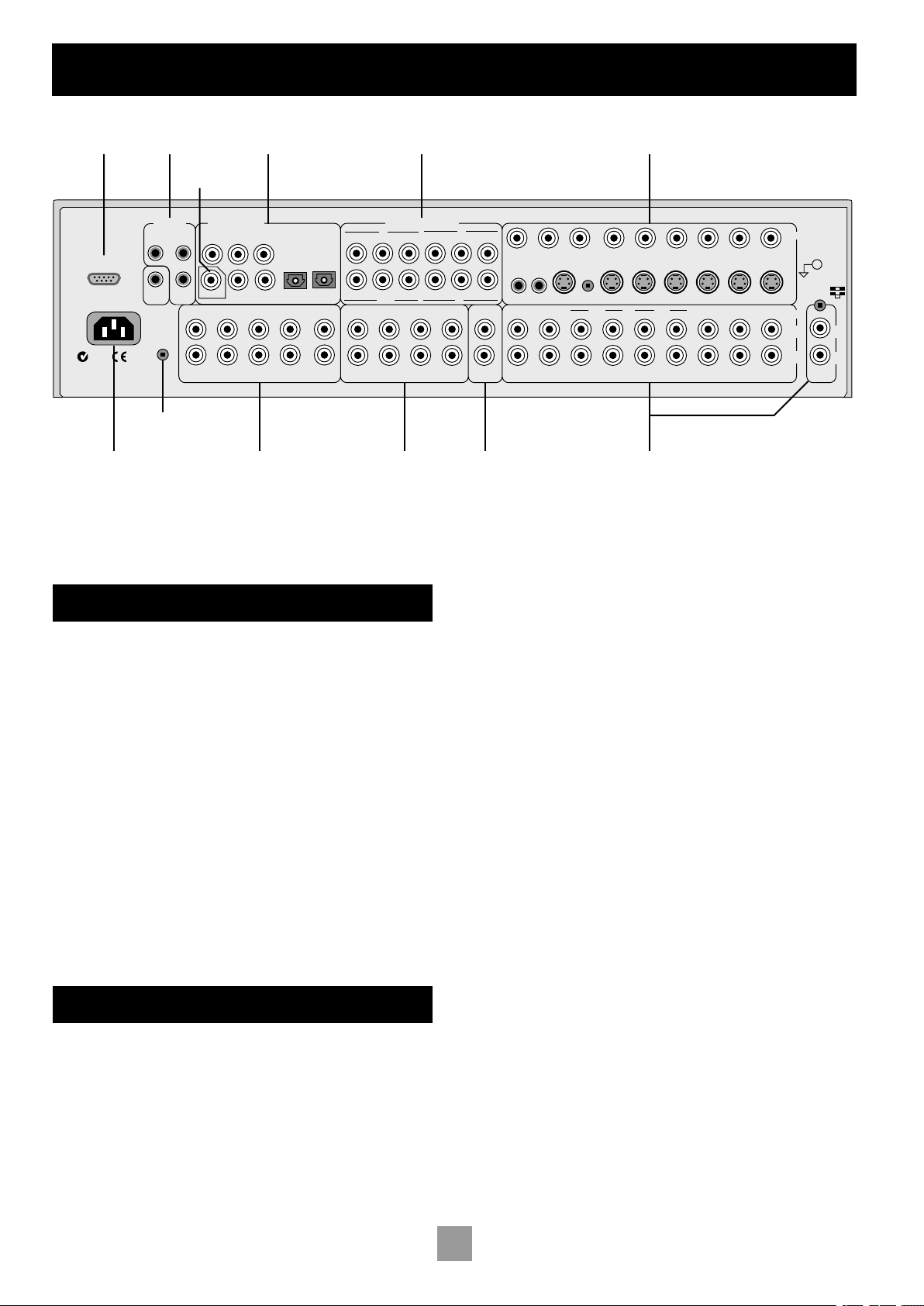
HIGH QUALITY VIDEO
DIGITAL INPUTS
REMOTE
ZONE 2 OUT
Serial
control
Digital
output
Digital audio
inputs
Component video
connections
Composite & S-video
connections
Zone
2
output
Analogue audio
inputs and record
outputs
Multichannel
DVD-A/SACD
inputs
Power supply
connector
Multichannel
outputs
Control
connections
Ground lift
Installation
E-5
English
GENERAL
The inputs are named to make it easier to reference when connecting
e.g., a DVD or VCR, but they all have the same input circuit, so there
is no reason why you should not connect a different device to any of
the inputs. For example, if you had two DVD players and the AV input
was not being used, then the second DVD player can be connected to
the AV input.
CABLES
We recommend the use of high quality screened analogue, digital and
video cables, as inferior quality cables will degrade the overall quality
of your system. Only use cables that are designed for the particular
application as other cables will have different impedance characteristics
that will degrade the performance of your system.
Video and digital connections must be made with cables that are
designed for this purpose, i.e., coaxial cable with a 75Ω impedance. If
substandard cables are used you may suffer from poor picture quality
such as ghost images and or grainy picture quality (snow).
Speaker cables should be kept short and low impedance wire should
be used throughout to ensure efficient power transmission and avoid
audible distortion.
All cables should be kept as short as is practically possible.
It is good practice when connecting your equipment to make sure that
the mains power supply cabling is kept as far away as possible from your
audio and video cables, as this will provide the best sound and picture
quality. Failure to do so may result in unwanted noise in the audio and
video signals.
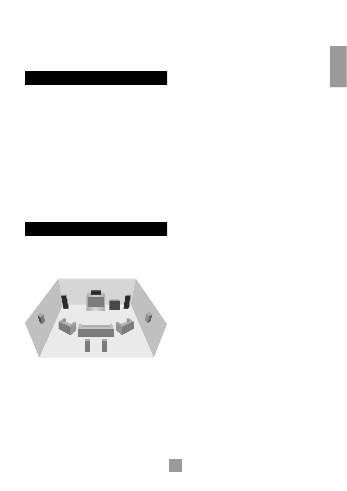
SPEAKER INSTALLATION
The AV8 allows you to connect up to seven channels of amplification
and three active subwoofers in the main system. The output channels
correspond to speakers installed in the front left, centre, front right,
surround left, surround right, surround back left, surround back right
and an active subwoofer (see diagram).
Surround
back left
Surround
back right
CentreFront
left
Front
right
Subwoofer
Surround
left
Surround
right
GENERAL
All speakers, with the exception of the subwoofer, should be arranged
around your normal viewing/listening position (see diagram). The
subwoofer can be placed almost anywhere and we recommend
experimenting with it in various positions to obtain the best result.
The configuration and placement of your speakers are very important.
For THX surround EX playback we recommend that you use a THX
speaker system that is certified by Lucasfilm Ltd. If you are not installing
a full THX surround EX system then ignore the instructions regarding
the surround back left and right loudspeakers.
FRONT LEFT AND RIGHT
Position your front left and right speakers to achieve a good stereo
image for normal musical reproduction as well as for the multichannel
modes. If they are placed too close together there will be a lack of
spaciousness; if they are placed too far apart a stereo image will appear
to have a large ‘hole’ in the middle and will be presented in two halves.
If there is no practical alternative to placing the speakers widely apart,
this effect can be overcome in music reproduction by using centre
sound extraction from the left and right speakers (see Dolby ProLogic
II Music Mode).
CENTRE
The centre speaker allows for a more realistic reproduction of dialogue
and centre sounds. The centre speaker should have a similar tonal
balance to the front left and right speakers and be positioned at a
similar height.
SURROUND LEFT AND RIGHT
The surround left and right speakers reproduce the ambient sound and
effects present in a multichannel home cinema system and should be
installed approximately one metre higher than the listener’s ears.
SURROUND BACK LEFT AND RIGHT
The surround back left and right speakers are used to add extra depth
and better sound localisation and should be installed approximately
one metre higher than the listener’s ears. Place the two surround
back speakers such that there is an arc of approximately 150 degrees
between each surround back speaker and the centre speaker. The
surround back speakers should face the front of the room as shown
in the diagram to provide the largest ‘sweet spot’. You will then need
to measure the distance between the two surround back speakers
and set the ‘Advanced Speaker Array’ line of the ‘THX Settings’ menu
accordingly.
SUBWOOFER
A subwoofer will greatly improve the bass performance of your system.
This is useful for reproducing special cinema effects, especially where
a dedicated LFE (Low-Frequency Effects) channel is available, as with
many Dolby Digital or DTS encoded discs.
Multiple subwoofers may be required for larger installations, particularly
in rooms of a timber frame construction. Multiple subwoofers need
care in placement because there may be cancellation effects between
the units. Seek expert advice on multiple subwoofer placement.

E-6
E-6
E-7
English
DIGITAL AUDIO INPUTS
bp
DVD, bq AV, br TAPE, bs TUNER, bt CD, ck VCR, cl SAT.
Connect these inputs to the digital ouputs of your available source
equipment.
bs bt ck clcm
OUT TUNER CD VCR
SA
T
TAPE
AV
DVD
bp bq br
DIGITAL INPUTS
Notes:
Each of these seven digital inputs can be individually allocated to
different audio inputs if required, by use of the ‘Digital Settings’
page of the Setup menu.
The AV8 does not contain an RF decoder for Laserdisc with RF
output.
DIGITAL OUTPUT
cm
(Digital) OUT. Connect this coaxial digital output to your digital
recording device such as a CD-R, digital VCR or minidisc player.
When a digital source is selected, the digital output will send an exact
copy of the incoming digital signal. For example, for a 5.1 digital source,
the digital output will also be in 5.1 format.
On selecting an analogue source, the digital output will send an SPDIF
format digital signal, encoded with the analogue source material, with
one exception: if Neo:6 Cinema or Music mode is selected, the digital
output will be muted due to the extra processing required for these
modes.
MULTICHANNEL DVD-A/SACD INPUTS
The multichannel input is suitable for use with sources that decode the
surround channels internally, such as DVD-A or SACD players.
The AV8 switches these analogue inputs directly to the analogue
outputs via its own volume control circuit. This direct path maintains
the best possible sound quality for DVD-A and SACD sources.
LEFT
RIGHT
CENTRE
SUB
L SURR
R SURR RS
BACK
co cq cs dk
cn cp cr ct
DVD-A/SACD IN
LS
BACK
cn
LEFT, co RIGHT, cp CENTRE, cq SUB, cr L SURR, cs R SURR.
Connect these input sockets to the equivalent audio outputs of your
DVD-Audio or SACD player.
ct
LS BACK, and dk RS BACK. These are available for formats
requiring eight channels. Currently no formats are available requiring
these connections, which are provided for future compatibility.
AUDIO CONNECTIONS
Take care to place the audio cables as far from any power supply cabling
as is practically possible to reduce hum and noise problems.
Connect the analogue outputs from your source devices such as a
DVD player to the analogue inputs as shown:
AUX/
PHONO
MM
MC
TUNER AV SAT DVDCD OUT IN
TAPE VCR
IN
AUDIO
L
R
OUT
6 8 9 bk bl bm
bn
bo
543 7
GND
ANALOGUE AUDIO INPUTS
3
TUNER, 4 CD, 6 TAPE 1N, 8 VCR IN, 9 AV, bk SAT,
bl
DVD. Connect the left and right inputs to the left and right outputs
of your source equipment.
bm
AUX/PHONO. Unless the optional phono card has been installed,
this input will function identically to the other line inputs. For example
it can be connected to a second CD player.
With the optional phono card installed this input can be connected
directly to a record deck. This card is available from your Arcam dealer
and caters for both moving magnet and moving coil cartridges.
bn
MM/MC Switch. The switch on the back panel marked MM/MC is
used to select the correct sensitivity to match the cartridge fitted to
the record deck, which is either moving magnet (MM) or moving coil
(MC).
If you are unsure which type of cartridge is fitted to your record deck,
connect the record deck and select the ‘MM’ setting on the switch. If,
when tested, the output from the record deck is very quiet compared
with the CD or DVD inputs then your cartridge is probably a moving
coil type cartridge. Turn the AV8 off and select the ‘MC’ setting on the
switch and test the record deck again.
Please note that if the AV8 is set to ‘MM’ and the record deck has a
‘MC’ cartridge fitted, testing these together will not cause any damage
to either the AV8 or the record deck.
bo
GND. This is the phono earth or ground terminal and is used to
connect to a turntable earth lead (if fitted). Note that this terminal must
not be used as a safety (mains) earth.
ANALOGUE RECORD OUTPUTS
5
TAPE OUT, 7 VCR OUT. Connect the left and right audio
outputs sockets to the left and right input sockets of your cassette deck
or VCR (usually labelled ‘RECORD’). The VCR connections may also be
used for a second tape deck.
E-7
English
ANALOGUE PREAMPLIFIER OUTPUTS
All these analogue outputs are buffered, have a low output impedance
and are at line level. They are able to drive long cables or several inputs
in parallel if required.
LEFT CENTRE L/SURR LS/BACKSUB/2
RIGHT SUB/1 R/SURR RS/BACKSUB/3
dm do dq ds ek
dl
dn
dp dr dt
OUTPUTS
dl
LEFT, dm RIGHT, dn CENTRE. Connect these to the equivalent
front channel inputs of your power amplifier.
do
SUB 1. Main subwoofer output. Connect this to the input of your
active subwoofer, if you have one.
dp
SUB 2, dq SUB 3. Subwoofer auxiliary outputs 2 and 3. These
are equivalent to do and allow the use of multiple subwoofers. If
you are using more than one subwoofer, please set the number used
on the subwoofer setting page. Refer to ‘Basic and Advanced Set up’,
‘Subwoofer Settings’.
dr
L SURR. Surround left output. Connect this output to the surround
left power amplifier input.
ds
R SURR. Surround right output. Connect this output to the
surround right power amplifier input.
dt
LS BACK, ek RS BACK Surround back left and right outputs (only
used in 7.1 channel systems). Connect these outputs to the inputs of
your LS back and RS back amplifiers.
ZONE 2 CONNECTIONS
The AV8 allows independent routing and control of analogue audio
and composite video to a separate set of equipment, typically used for
a second living space, e.g., bedroom or lounge.
Zone 2 only outputs a signal from the analogue audio and composite
video inputs. The analogue inputs are required because there is no
analogue-to-digital, digital-to-analogue or DSP processing available for
zone 2 signals.
As the AV8 does not convert video formats a composite signal must
also be connected from the source.
For this reason we recommend that source devices that have a digital
connection are also connected to the analogue inputs. High quality
YUV/RGB and S-video sources should also have their composite
output connected to the AV8 for use in zone 2.
ZONE 2
OUT
gp
gl gn
gm go
OUT
IN
LOCAL
12V
TRIGGER
IN
ZONE
2
REMOTE
ZONE 2
MONITOR OUT
2
1
gr
VIDEO
TRIGGERS
1/RGB 2/S-VIDEO
PROG
gp
ZONE 2 OUT. Connect these to a line level input on your zone
2 amplifier.
go
IN ZONE 2. This allows the AV8 to be controlled remotely from
zone 2 via infrared remote control.
A receiver compatible with this connector is available from Xantech
(part no. 291-10). Please contact a Xantech registered dealer for this
part, as ARCAM do not stock them. See www.xantech.com for more
information.
The 3.5mm jack plug for this connector is wired as follows:
3.5mm stereo jack Function
Tip Signal
Ring 0V
Sleeve 12V, 30mA current-limited
This follows the Xantech standard for IR transmission over wire.
gr
ZONE 2 Composite video connection. Connect to your zone 2
video display using 75Ω low loss coaxial cable.
VIDEO CONNECTIONS
IMPORTANT NOTES
The AV8 has no video format conversion between component, RGB,
S-video or composite.
Wherever possible connect multiple video outputs from your video
sources. This enables use of the higher quality video connection for
the main system and the corresponding S-video and composite
connection for the record and zone 2 outputs.
For any video source to be viewed in zone 2 you must have a
composite video connection between the source and the AV8.
COMPOSITE VIDEO CONNECTIONS
ZONE 2
AV SA
TMONITOR OUT DVD
VCR
OUT
2
1
TAPE
VIDEO
el em en eogr
eq er esep
fl fm fn fo fp fqetgs
VCR
IN
VIDEO
TRIGGERS
1/RGB 2/S-VIDEO
PROG
fk
gt
el
MONITOR OUT 1. Connect this output to the composite video
input of your display device. (You will need an RCA phono-to-phono,
or, in Europe, a phono-to-SCART video cable to do this.)
em
MONITOR OUT 2. This is the same as el MONITOR OUT 1, and
enables a second display device to be used; it can also be used as a sync
reference for a four-wire RGB signal.
ep
VCR IN, eq AV, er SAT, es DVD. Connect these inputs to the
composite video outputs of your source equipment.
eo
VCR OUT. Connect to the composite video input of your video
recorder (you will need an RCA phono-to-phono or, in Europe, a
phono-to-SCART video cable to do this).
en
TAPE. If you are using the tape loop for a second VCR then connect
the composite video from the VCR to this input.
S-VIDEO CONNECTIONS
et
MONITOR OUT. Connect this to the S-video input of your display
device.
fn
VCR IN, fo AV, fp SAT, fq DVD. Connect these inputs to the
S- video outputs of your source equipment.
E-8
E-8
E-9
English
fm
VCR OUT. Connect this to the S-video input of your video
recorder.
fl
TAPE. If you are using the tape loop for a second VCR then connect
the S-video from the VCR to this input.
HIGH QUALITY (COMPONENT) VIDEO
CONNECTIONS
These inputs are suitable for connection to component (YUV/ YCrCb)
or RGB outputs. These signals are usually available from a DVD player,
set-top box or games console and offer the best possible picture
quality.
Generally, the component video standard is used in North America/
NTSC regions, while RGB is used in Europe.
Y/G U/B V/R Y/G V/R
1
2
V/R Y/G U/B V/R
OUT
3
fr
U/BY/G
U/B
fs
ftgk
HIGH QUALITY VIDEO
fr
VIDEO 1, fs VIDEO 2, ft VIDEO 3 INPUTS. Connect these to
the video outputs of your high quality video sources.
gk
HIGH QUALITY VIDEO OUT. Connect these sockets to the
component video inputs of your display device.
Important notes about HQ video inputs and outputs
When you connect your devices to these connectors, take care to
follow the letter/colour coding for each input. No damage will occur if
incorrectly connected, but unusually coloured or unstable pictures will
result.
In the ‘Video Settings’ setup menu, each of these three high quality
component video inputs can be individually allocated to one of the
following inputs: DVD, SAT, TUNER, TAPE, CD, VCR or AV.
You cannot mix component and RGB sources.
The high quality component video inputs have sufficient bandwidth for
line-doubled NTSC (525/60) or PAL (625/50) video and US HDTV
video signals. However, when used with such signals the OSD is not
overlaid on the picture but is output at standard interlaced NTSC or
PAL (525 or 625 line) rate on a solid background.
Initially, the high quality video inputs are all disabled. Before any HQ
video input can be selected it must be allocated to an input.
RGB 4-wire connection
Some video projectors and most European TV sets require the use of
a 4-wire RGB connection, where the ‘sync’ signal is separate from RGB.
In this case, you need to use the composite video MONITOR OUT 2
for the sync information. A special cable is available from your dealer
for 4-wire RGB connection (refer to the table of SCART connections
at the back of the manual).
CONTROL CONNECTIONS
gl gn
gm go
OUT
IN
LOCAL
12V
TRIGGER
IN
ZONE
2
REMOTE
GROUND
LIFT (IN)
RS232
CONTROL
85 – 265VAC
MAX 40VA
gq
gn
IN LOCAL. Use with a local IR receiver when the AV8 front panel
IR receiver is obstructed.
go
IN ZONE 2. This allows the AV8 to be controlled remotely from
zone 2 via infrared remote control.
A receiver compatible with this connector is available from Xantech
(part no. 291-10). Please contact a Xantech registered dealer for this
part, as ARCAM do not stock them. See www.xantech.com for more
information.
The 3.5mm jack plug for this connector is wired as follows:
3.5mm stereo jack Function
Tip Signal
Ring 0V
Sleeve 12V, 30mA current-limited
This follows the Xantech standard for IR transmission over wire.
Connect to a remote IR receiver in zone 2 to allow control of the AV8
from zone 2.
gl
(REMOTE) OUT. This enables control of the source components
remotely from zone 2 or zone 1 using the local input. Control is
possible by either connecting to the source devices via the 3.5mm IR
jack (Arcam units only) or using an IR emitter stuck to the centre of
the IR sensor window on the source component (such as a Xantech
283MW mini emitter).
gq
RS232 CONTROL Use with control devices having an RS232 serial
port (for example, Crestron and AMX touch screen controllers). This
connection is also used for upgrading control software. See the sections
at the end of this manual for control and programming information.
TRIGGER OUTPUTS
There are three trigger output sockets on the AV8, each of which is a
3.5mm stereo jack with two contacts, ‘tip’ and ‘ring’. See the tables for
technical information on the trigger outputs.
gm
12V TRIGGER. Use for remotely turning on and off power amps or
source equipment for the main zone and zone 2.
3.5mm stereo jack Function Voltage
Tip Main zone on On = 12V, 30mA
Off = 0V
Ring Zone 2 on On = 12V, 30mA
Off = 0V
Sleeve Ground 0V
E-9
English
gs
VIDEO TRIGGER 1, gt VIDEO TRIGGER 2. The trigger outputs
have different functions depending on how the ‘Video Status’ has been
set (Screen Ctrl or SCART) in the ‘General Settings’ menu.
ZONE 2
MONITOR OUT
2
1
VIDEO
TRIGGERS
1/RGB 2/S-VIDEO
PROG
gs
gt
SCART mode
1/RGB trigger output – connect to RGB SCART on your TV:
Connection Function Voltage
Tip RGB mode select RGB video = 1V (into 75Ω load)
Composite video = 0V
Ring RGB/composite
SCART input select
(CVBS status)
Aspect ratio 4:3/16:9
Video present, aspect 4:3 = 12V
Video present, aspect 16:9 = 6V
No video signal = 0V
Sleeve Ground 0V
2/S-video output – connect to S-video SCART (usually SCART no.
2) on your TV:
Connection Function Voltage
Tip Video source
trigger*
Any video source selected = 12V
No video source selected = 0V
Ring S-video SCART
input select (CVBS
status)
Aspect ratio 4:3/16:9
S-video present, aspect 4:3 = 12V
S-video present, aspect 16:9 = 6V
No video signal = 0V
Sleeve Ground 0V
Notes on SCART mode
In SCART mode, seamless selection of composite, S-video and RGB
A/V TV inputs is possible using the AV8.
When switched to a video source input, and the AV8 detects the
presence of either an S-video or composite video signal, it sets either
the S-video or the composite SCART input select lines high. If both
signal types are detected on that source input, then only the S-video
SCART input select line is set high.
If a high quality video source in RGB+Composite Syncs mode is
allocated to an input, the AV8 will assume an RGB signal is present
when syncs are detected on the composite input. In this case if only a
composite video signal is present on the input the AV8 will detect this
as an RGB+Composite Sync signal and display a blank screen, not the
composite video signal.
Information on SCART wiring is provided in the back of this manual.
NOTE: When the ‘HQ Video’ line of the ‘General Settings’ page is set
to ‘Component’ (rather than ‘RGB’), video trigger 1 behaves as listed
in the table for Screen Ctrl mode.
Screen Ctrl mode
1/RGB trigger output:
Connection Function Voltage
Tip Main zone on trigger Main zone turned on = 12V
Main zone turned off = 0V
Ring Main zone on trigger Main zone turned on = 12V
Main zone turned off = 0V
Sleeve Ground 0V
2/S-video output:
Connection Function Voltage
Tip Video source
trigger *
Any video source selected = 12V
No video source selected = 0V
Ring Video source
trigger *
Any video source selected = 12V
No video source selected = 0V
Sleeve Ground 0V
* Video source trigger – This output goes high when any video source
in the main zone is selected. It can be used to initiate closing of curtains
or dimming lights automatically.
Notes on Screen Ctrl mode
In Screen Ctrl mode, the video triggers behave differently. Both
outputs of video trigger 1 double up the role of the 12V trigger
output described earlier. They can be used to remotely switch on or off
additional equipment such as power amplifiers.
CONNECTING TO A POWER SUPPLY
1
Power inlet. The AV8 has a universal input power supply that is
compatible with mains voltages between 85VAC and 265VAC.
GROUND
LIFT (IN)
RS232
CONTROL
85 – 265VAC
MAX 40VA
1
2
2
GROUND LIFT (IN) button. In complex setups which involve satellite
inputs or radio aerials, grounding the unit may increase the level of
background hum or buzz in the loudspeakers, in which case press the
GROUND LIFT button in to lift the signal ground from the chassis ground.
DO NOT REMOVE the safety earth from the mains cable under any
circumstances.
WRONG PLUG?
Check that the plug supplied with the unit fits your supply. If your
mains plug is different, consult your Arcam dealer or Arcam Customer
Support on +44 (0)1223 203200.
MAINS LEAD
The appliance is normally supplied with a moulded mains plug already
fitted to the lead. If for any reason the plug needs to be removed, it
must be disposed of immediately and securely, as it is a potential shock
hazard when inserted into the mains socket. Should you require a new
mains lead, contact your Arcam dealer.
PLUGGING IN
Push the plug (IEC line socket) of the power cable supplied with the
unit into the power input socket (1) in the back of the unit. Make sure
it is pushed in firmly.
Put the plug on the other end of the cable into your power supply
socket and switch the socket on.

E-10
E-10
E-11
English
The AV8 ‘Setup Menu’ has six ‘Basic’ and five ‘Advanced’ menu screens
which take you through the configuration process. The ‘Basic’ menus
enable you to match your AV8 to your speakers. The ‘Advanced’ menus
allow you to optimise the operation of your system. Screen shots of
these menus are shown in shaded boxes on the following pages.
The best way to set up the AV8 is using the on-screen display (OSD).
To view the OSD for the initial set up, use the composite video output
because the high quality video output has several display modes, and
may be incompatible with your high quality display device in its default
configuration.
The AV8 defaults to the NTSC video standard – most display devices
can sync to this automatically. For PAL-only display devices, press and
hold the OK button for two seconds, when the AV8 will change to the
PAL video standard. As soon as a video signal is input to the AV8, it
automatically detects which standard it is and switches to it.
ENTERING SETUP MODE
To enter the Setup menus press and hold the MENU button on the
remote control, or on the front panel, for at least two seconds. The
‘Setup Menu Index’ is displayed on your display device.
Unstable OSD menu display?
Your AV8 may be in the wrong video standard mode. Press and hold
the OK button for more than two seconds to switch between the
NTSC and PAL standard OSD mode.
SETUP LOCK
To prevent tampering with the AV8 setup configuration you can ‘lock’
the menus by pressing the OK, TUNER and DVD-A buttons simultaneously
on the front panel. To unlock the AV8, press the same buttons again.
SETUP MENU
The main ‘Setup Menu’ page allows you instant access to six ‘Basic’ and
five ‘Advanced’ menus.
Setup Menu Index
Basic Advanced
1.General 1.Speaker EQ
2.Speaker Size 2.Video
3.Delays 3.Digital
4.Level Set 4.Zone 2
5.Sub Woofer 5.Input Trim
6.THX
Save Setup Exit Setup
They are listed side-by-side on the OSD on your display device. The
selected line of the menu is also displayed on the front panel of the
AV8. Use the remote control navigation button4to go to page 1 from
the menu heading, or use the navigation buttons to scroll down the list
to a specific page, then press OK to go directly to the page.
Save Setup takes you to the ‘Save Settings’ screen to allow you to
save in one of the five available presets.
Exit Setup exits the Setup menus without saving any changes.
Each of the following sections shows the screen that is displayed as you
move through the menus.
NAVIGATING USING THE REMOTE CONTROL
There are two ways to navigate through the Setup menus using the
remote control. The first method is for use when setting up the AV8
for the first time and allows you to progress methodically through the
menus:
1. Press and hold the MENU button (which is located immediately
under the navigation buttons) for two seconds to access the
‘Setup Menu Index’.
NOTE: Just briefly pressing the menu button takes you to
‘Main Menu Screen1’.
2. Navigate between menus using the
34
keys (the menu heading
must be highlighted).
3. Navigate up and down the menu lines using the
56
keys.
4. Cycle through the options and select the required setting using
the
34
keys.
Return to the title bar and repeat sequences 2 to 4, working through
the six ‘Basic’ menus and the five ‘Advanced’ menus as required.
5. Press the MENU button to return to the main Setup menu
screen.
6. Press the OK button twice to select ‘Save Setup’ and save the
settings. This takes about four seconds. Then press OK twice again
to return to the Index, then exit the Setup menu.
A second method can be used when you need to make adjustments
to a specific menu screen:
1. Press and hold the MENU button for two seconds to access the
‘Setup Menu Index’.
2. Navigate up and down the ‘Setup Menu Index’ using56,
pressing OK to go to the selected menu option.
3. Use
56
to navigate up and down the menu lines.
4. Use
34
to cycle through the options and select the required
setting.
5. Press MENU to return to the main setup menu screen.
6. Press the OK button twice to select ‘Save Setup’ and save the
settings. This takes about four seconds. Then press OK twice again
to return to the Index, then exit the Setup menu.
NOTE: It is always possible to navigate between menus using the title
bar at the top of each menu page.
NAVIGATING USING THE FRONT PANEL
The AV8 front panel controls can be used to configure the options.
Please note that it is easier to configure using the remote control.
1. Press and hold the MENU button for two seconds to access the
Setup menu.
2. Navigate up and down the ‘Setup Menu Index’ menu using56,
pressing OK to go to the selected menu option.
3. Use
56
to navigate up and down the menu lines.
4. Use
34
to cycle through the options and select the required
setting.
Return to the title bar and repeat sequences 2 to 4, working through
the six ‘Basic’ menus and the five ‘Advanced’ menus as required.
5. Press MENU to return to the main setup menu screen.
6. Press the OK button twice to select ‘Save Setup’ and save the
settings. This takes about four seconds. Then press OK twice again
to return to the Index, then exit the Setup menu.
Conguring the AV8
E-11
English
BASIC SETUP
1 – GENERAL SETTINGS:
1 - General Settings
Volume Display: Normal 0-72
Max Volume: +72
Max On Volume: +20
Delay units: Imperial
OSD Mode: Mixed
Video Status: SCART
HQ Video: RGB
Sync On Green: Off
Volume display: Allows you to select how volume is displayed.
Choose from Normal 0–72 (in 1dB steps), THX Ref –53dB to +18dB,
and Fine 0–72 (in 0.5dB steps). We recommend setting this to THX
Ref as this represents a volume control around 0dB (the reference
level) which is the same loudness level of a movie in a movie theatre
once you have correctly calibrated your system.
Max Volume: Limits the maximum volume setting the system can be
turned up to. This is a useful feature to prevent accidental overdriving
of low power-handling speakers, for example.
Max On Volume: Limits the maximum volume the system operates
at when it is first switched on. The system comes on at this volume if
the last used (possibly very loud) volume exceeds this value.
Delay units: Controls whether the delay settings for the speakers
in surround modes are specified in terms of Time, Imperial or
Metric distances from the listening position. Either enter the time
delay to each channel if calculating the delay in milliseconds, or select
between Imperial or Metric measurements to calculate the time delay
automatically. Imperial is measured in feet and Metric is measured more
precisely in 0.1m (10cm) increments. Note that 1 foot is approximately
0.3 metres.
NOTE: Changing the units resets all distances/times to zero. It is
therefore important to choose the units (Time, Imperial or Metric)
before set up.
OSD Mode: Controls how the on screen display is viewed. Mixed
will overlap the OSD on top of the existing video picture, while Full
Page will give a full screen black background with the OSD displayed
in white.
NOTE: In Mixed mode, the highlight bar is black if video is present. It
is blue if no video signal is present or if in Full Page mode.
Video Status: Can be set to Screen Ctrl or SCART. This controls the
triggers (Video Trig 1) into the display device to tell the display what
video type is being used. SCART refers to the multipole A/V connector
commonly used on European A/V equipment.
HQ Video: Allows selection of the high quality video output to match
your display device. Choose between RGB or Component. The AV8
allows progressive scan and high definition TV (HDTV) signals to be
passed through the high quality component inputs to the high quality
output. Note that the OSD cannot overlay text at any rate other than
standard NTSC or PAL.
On video signals that have a sync rate of greater than the normal
interlaced rate (i.e., progressive scan, frame-scaled video, HDTV) the
OSD will automatically go into Full Page mode (black background) so
that the control menu can be accessed. Any pop-up displays (such as
the volume bar, source selection information, etc) will be switched off.
Sync On Green: This applies only if RGB video is used. On makes
the AV8 feed the video sync signal out with the green signal. Some
RGB-driven display devices require a sync signal on the green input
to lock on to the video signal coming in, while others need the video
synchronisation on a separate lead. Systems using SCART connections
will normally have a four-wire system (i.e., with sync on composite
[CVBS] video).
NOTE: The ‘Sync on Green’ menu option is not selectable when
‘Component’ is selected as the HQ video type.
2 – SPEAKER SIZES
The size and number of loudspeakers are defined on this page of the
OSD.
2 - Speaker Sizes
Auto Setup: Custom
Front L/R: Small
Centre: Small
Surr.L/R: Small
Surr.Back L/R: Small
Subwoofer: Present
Rears for 5.1: Both
A note on speaker sizes
A Large speaker is one that is capable of handling a full range signal (i.e.,
20Hz–20kHz).
A Small speaker is one that is not capable of reproducing a deep bass
signal (i.e., below 100Hz), for example a satellite speaker.
None is used when there is no speaker connected to that channel.
Auto Setup: Allows the setting of ‘standard configurations’ as in the
table below:
Speaker Config 1 Config.2 Config.3 Custom THX THX
Surr.Ex
Front
L/R
Small Large Large Sm/Lge Small
THX
Small
THX
Centre Small Small Small Sm/Lge/
None
Small
THX
Small
THX
Surr
L/R
Small Small Large Sm/Lge/
None
Small
THX
Small
THX
Surr
Back
L/R
Small Small Small Sm/None None Small
THX
Subwoofer
Present None Present Present/
None
Present
THX
Present
THX
5.1
Rears
Both Both Both SurrL/R/
Sur Back
L/R/Both
Surr
L/R
Both
Custom setting allows you to choose any combination of speakers to
suit your system. Note that the centre and rear speakers cannot be set
to large if the front speakers are set to small.
THX automatically sets the speaker selections to the specified
configuration for THX™ listening. This automatically sets the
surround back speakers to None‚ and all filters are set to 80Hz. This
configuration is not adjustable. Only select this if you are using a full set
of THX™certified speakers.
THX Surr.EX automatically sets the speaker selections for a THX™
Surround EX setup with a pair of surround speakers, a pair of surround
back speakers and all filters set to 80Hz. This configuration is not
adjustable. Only select this if you are using a full set of THX™ certified
speakers.
E-12
E-12
E-13
English
5.1 Rear speakers defines how the speakers in a full ‘7.1’ installation
handle 5.1 decoded sources.
Surr L/R redirects 5.1 surround signal to the surround left and
right speakers. No signal will be directed to the surround back
left or right speakers.
Surr Back L/R redirects 5.1 surround signal to the surround back
left and right speakers. No signal will be directed to the surround
left or right speakers.
Both redirects the 5.1 surround signal to both pairs of speakers
with the signal to each set reduced by 3dB.
3 – SPEAKER DELAY SETTINGS
3 - Delay Settings
Front Left: 3Ft
Centre: 3Ft
Front Right: 3Ft
Surr. Left: 3Ft
Surr. Back L/R 3Ft
Surr. Right: 3Ft
Subwoofer: 3Ft
NOTE: Only enter these delay settings once you have specified what
delay units (i.e., Time, Imperial or Metric) you will be using, or the
information will be lost when changing units. If the delay units are set
to Time, then enter the delay in milliseconds for each channel.
The speaker distance control automatically sets the appropriate time
delays required for all the speakers in your system. To set up the correct
speaker distance, you must measure from the usual listening position to
the front of each individual speaker in the system. The delay adjustment
is not a substitute for proper speaker placement – it helps to ensure
accurate and correct signal arrival times from all the channels to the
primary listening position.
No measurement can be entered for a speaker that is not selected in
the previous ‘Speaker Sizes’ menu.
Fr
ont
left
Surr
left
Surr
right
Surr
back
left
Sub
woofer
Fr
ont
right
Centre
e.g. 3m
(9ft)
e.g. 4m
(12ft)
e.g. 2m
(6ft)
Surr
back
left
Surr
back
right
Distance measurements for 5.1 [and 7.1]
speaker delay settings
4 – LEVEL SETTINGS
4 - Level Settings
Test Tone Cycle: Manual
Front L: ---I--- +0dB
Centre: ---I--- +0dB
Front R: ---I--- +0dB
Surr. R: ---I--- +0dB
Surr. BR: Not Present
Surr. BL: Not Present
Surr. L: ---I--- +0dB
Subwoofer: ---I--- +0dB
Select Speaker for Tone
It is very important to calibrate the speakers correctly to achieve an
accurately centred sound stage. We recommend you use a sound
pressure level meter (SPL meter) to perform this part of the setup as
it is difficult to judge the levels accurately by ear alone.
Manual is best for setting up with an SPL meter as the test tone will
not change to the next speaker until instructed by you. Auto is best for
setting up by ear as the test tone changes automatically to each speaker
after a two second burst of sound.
On first installation, watch the OSD display as you cycle through the
available speakers with the test tone. Check that the speaker in use
corresponds to that indicated on the OSD. If there is an error then
check and correct the system cabling before proceeding further.
To calibrate the speakers with an SPL meter, place the meter at ear
level with the microphone pointing towards the ceiling, when seated in
the usual listening position. You will need to set the meter to ‘C’‚ setting
with a ‘slow’‚ response and to read 75dB SPL at the centre of the scale.
This volume is equivalent to normal conversation.
Each speaker can be finely tuned by 1dB increments to ±10dB. The
output from each speaker needs to be adjusted to the 75dB SPL sound
level. No adjustments can be made for a speaker that is not selected in
the previous ‘Speaker Sizes’ menu.
NOTE: If you do not have an SPL meter, simply set the front left
speaker to 0dB on the menu and then match all the other speakers
to this level.
5 – SUBWOOFER SETTINGS
If no subwoofer was selected in the previous speaker menus you
cannot adjust the stereo sub level or the number of subwoofers.
5 - Subwoofer Settings
Crossover Freq.: 80Hz THX
Stereo Mode: Sat+Sub
LFE Level: ---I--- -0dB
DTS LFE Gain: 0dB Normal
Sub Stereo: ---I--- -0dB
DVD-A Sub Level: Normal
No. of Subwoofers: 1
Crossover Frequency: Allows you to set the frequency at which
the signal is redirected from small speakers to the subwoofer or large
speakers. The adjustment can be made in increments of 10Hz between
40Hz and 150Hz.
If THX or THX Surr.EX have been selected in the previous menus, the
crossover frequency will be set to THX specification at 80Hz.
Stereo Mode: Select between Large, Large+Sub or Sat+Sub. You
have the flexibility to choose how bass information is distributed to
your speakers only if you have large front left and right speakers and
a subwoofer as part of your home theatre speaker system. To decide
which setting is best for your room, once you have positioned all of
your speakers, choose the option which gives you the most solid even
sounding bass using a setup disc or live program material.
Large Pure stereo information. Use this setting if you have large
front speakers.

E-13
English
Large+Sub Pure stereo fed to left and right and extracted bass is
sent to the subwoofer.
Sat+Sub Use this setting if you have ‘Small’ satellite left and right
speakers. Full bass management is used in analogue stereo so
that analogue sources are fed to the DSP where the bass is
filtered off left and right and redirected to the subwoofer.
NOTE: The above three Stereo Mode settings pass the audio
through the DSP. The Large setting can be duplicated for analogue
inputs by pressing Direct to bypass the DSP.
LFE Level: Allows you to adjust the output level of the low frequency
effects channel relative to the other speakers in the system. This
adjustment affects the loudness of movie low frequency effects such as
thunder, explosions, etc.
DTS LFE Gain: DTS soundtracks typically have the LFE track recorded
10dB lower than the main audio tracks. It is therefore necessary to
compensate for this by raising the LFE output level by 10dB. Setting the
DTS LFE gain to Normal activates this compensation.
Some DTS soundtracks have been recorded with the LFE signal at
the same levels as the main audio and therefore require no gain
compensation. For these disks set the DTS LFE gain to -10dB.
Sub Stereo: Allows you to trim the subwoofer output for stereo
listening. Use this trim setting, with a stereo source, to reduce the
subwoofer output in stereo playback to an acceptable level. The
subwoofer level for stereo music often needs to be set at a lower
level than that for cinema use. This depends on various factors such as
speakers, the types and styles of music to be played and personal taste.
DVD-A Sub Level: External decoder sub level outputs are typically
the same level as the main audio and therefore require no gain
compensation. For these decoders set the DVD-A sub level to Normal,
the default setting.
Some external decoders may have the sub output 10dB lower than the
main audio outputs. It is therefore necessary to compensate for this by
raising the sub level by 10dB. Setting the DVD-A sub level to +10dB
activates this compensation.
No. of subwoofers: Allows you to set the number of subwoofers
used in the system from 1 to 3. All three subwoofer outputs are active
all the time. This setting compensates the sub output level for the
number of subwoofers in the system.
6 – THX SETTINGS
6 - THX Settings
THX Surr. EX: Auto
Boundary Gain Compensation
THX Ultra 2 Sub: No
Advanced Speaker Array
SurrBack L/R: 12 to 48in
6 - THX Settings
THX Surr. EX: Auto
Boundary Gain Compensation
THX Ultra 2 Sub: Yes
Boundary Gain Comp: On
Advanced Speaker Array
SurrBack L/R: 12 to 48in
THX Surr. EX: This can either be set to Auto or Manual and is only
applicable when playing THX Surr. EX encoded material.
Auto The AV8 automatically switches THX to THX Surr. EX when
suitably encoded material is detected (this can be temporarily
overridden by pressing the THX button on the AV8).
Manual The AV8 will not select THX Surr. EX automatically. It
can however be selected manually by pressing the THX button.
Boundary Gain Compensation
THX Ultra2 Sub: THX Ultra2 specified subwoofers can effectively
deliver down to 20Hz, which may be problematic in some rooms.
Set to No if the subwoofer being used is not a THX Ultra2 specified
subwoofer, or is not capable of a good response to 20Hz.
Set to Yes If you are using a 20Hz subwoofer or a THX Ultra2
specified subwoofer. When set to Yes, another menu option
appears.
Boundary Gain Compensation: Tailors the subwoofer low
frequency response.
When set to On, this will roll off the very low frequency
information coming from the subwoofer so that any interactions
and reinforcements from nearby boundaries (i.e., walls) can be
compensated for to reduce boom and overblown bass response.
We recommend this setting for smaller rooms.
When set to Off, the subwoofer output from the AV8 will
remain flat to 20Hz.
Advanced Speaker Array: Set this distance to be the separation
between the surround back left and right speakers. This enables the AV8
to distribute the signal to the surround back speakers appropriately to
get the most accurate image for the soundstage.
Surr
left
Surr
right
Surr
back
left
Surr
back
left
Surr
back
right
Measurement units are in inches only, 30cm = 12 inches.
SAVING SETTINGS AND EXIT SETUP
You can either save the settings now and exit or continue to the
‘Advanced Setup’ instructions.
Save Setup
1. Press MENU to go to the ‘Setup Menu Index’ at the ‘Save Setup’
point.
2. Press OK to go to the ‘Save Settings’ menu.
3. Press
56
to select the desired ‘Preset’ to which to save the
setting.
4. Press OK twice to save and exit to ‘Setup Menu Index’.
5. After the AV8 has finished saving, press OK to return to the
‘Setup Menu Index’.
6. Press OK to select ‘Exit Setup’ and exit system configuration.
NOTE: It is possible to change the name of the presets – see the
‘Advanced Settings’ section for a more detailed explanation.
Exit without saving
If you choose to ‘Exit Setup’ without first saving the changes, then these
new settings will be used by the AV8 until you recall a preset or press
FAV on the remote control, when the last used preset will be recalled.
This is the case even if the AV8 is put into standby or turned off.
1. Press MENU to go to the ‘Setup Menu Index’ at the ‘Save Setup’
point.
2. Press4to select ‘Exit Setup’.
3. Press OK when ‘Exit Setup’ is selected to exit system
configuration.