

Page 1
Audiophile products
from A&R Cambridge
Delta
60 in*®9'“*‘^handbook
Page 2

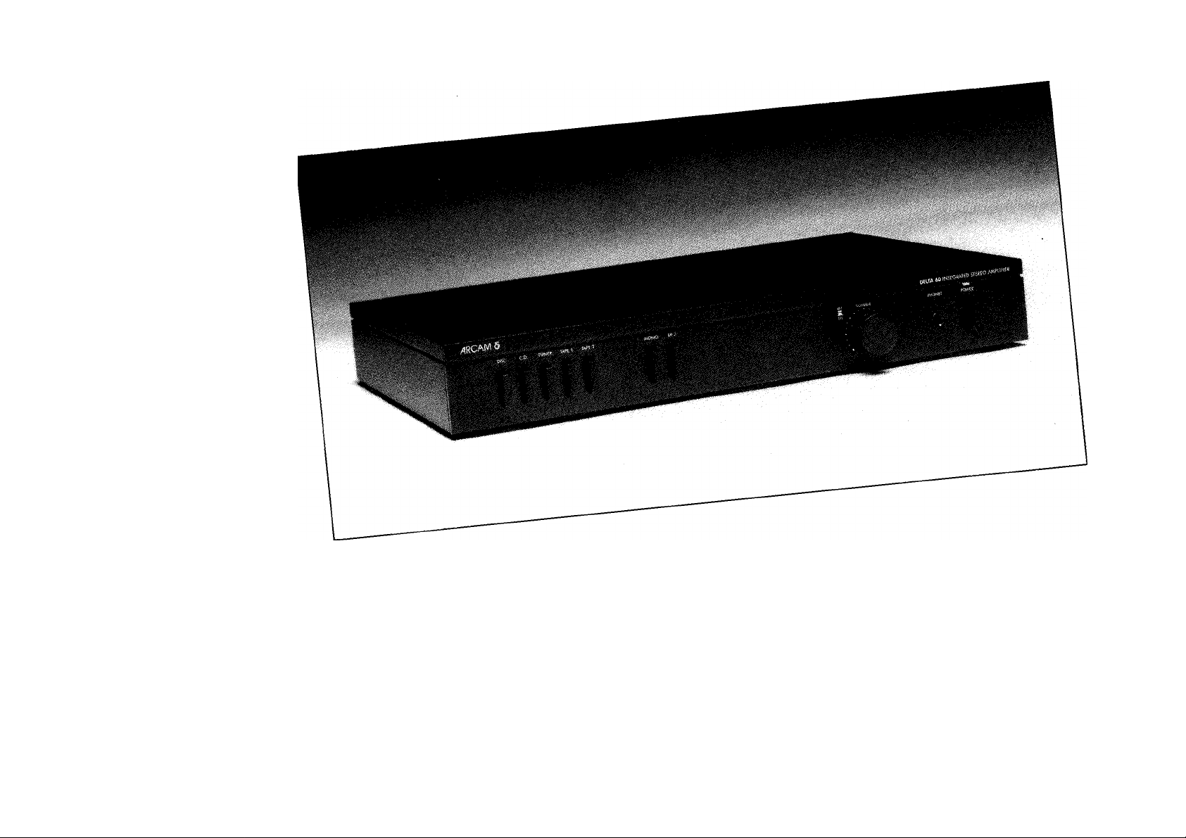
Delta 60 integrated amplifier handbook
Introduction
The Arcam Delta 60 integrated amplifier is a product
constructed to a purist design, as evident by its lack of tone controls, which
will meet the requirements of the most demanding listener. Combining
excellent sound quality with sleek, sophisticated styling, the Delta 60 will
form the heart of any high quality sound system. It is, of course, ideally
suited for use with our existing Delta range units, especially the Delta 80
tuner. Delta 70.2 CD player and Black Box D/A converter.
The Delta 60 has five switchable inputs accepting signals from
compact disc, turntable (with facilities for moving magnet and moving coil
cartridges), tuner and two tape recorders. The Delta 60 offers further
versatility by providing outputs for headphones and two sets of
loudspeakers and by allowing mono operation.
Please study these instructions carefully to ensure that you get
the best from your Delta 60. Remember that your dealer is there to help
you. He has full knowledge of all Arcam products and considerable
experience of their use in a variety of systems. If, however, he is unable
to answer your query then please contact us at the factory.
Page 3

Delta 60 integrated amplifier handbook
Installing and using your Delta 60 Amplifier
Mains supply
The Arcam Delta 60 may be supplied to work on any of the
following AC voltages: 110/220V and 120V/240V (1OOV units can be
supplied to special order). Check that your local mains supply voltage
agrees with the voltage setting indicated on the back panel of the Delta
60. If not, please contact the factory or your national distributor for details
of how to proceed further.
A detachable mains lead is supplied with the Delta 60. The
cores of this lead are coloured in accordance with the following code;
Green and yellow - Earth
Blue - Neutral
Brown - Live
Note: Export units for certain markets have moulded mains
plugs fitted as standard.
As the colours in the mains lead may not correspond with
the coloured markings identifying the terminals in your plug proceed
as follows;
The wire which is coloured green and yellow must be
connected to the terminal in the plug which is marked by the letter E or to
the safety earth symbol or coloured green or green and yellow. The wire
which is coloured blue must be connected to the terminal which is marked
by the letter N or coloured black or blue. The wire which is coloured
brown must be connected to the terminal which is marked by the letter
L or coloured red or brown.
Fuses
If the mains plug is fused fit a 5 amp fuse.
The AC supply inlet to the Delta 60 uses a standard lEC
chassis mounting plug.
The lEC line socket on your mains lead and the lEC plug on the
Delta 60 are a tight fit; before first using the Delta 60 it is therefore
important to ensure that the socket is firmly pushed home into the
chassis plug.
Under no circumstances should the Delta 60 cover be
removed unless the supply is disconnected at the wall socket.
Notice
1 Please retain the carton and all packaging materials
provided with this equipment so that it may be repacked correctly if it
ever becomes necessary to transport the unit or to return it for service.
2 If servicing is required then the equipment should be
properly packed and returned to the dealer from whom it was
purchased. It is essential to include a covering letter giving your name
and address and a brief but thorough description of the fault.
Connections
It is advisable that your system be switched off before
connecting it up to the Delta 60. This will avoid possible damage to your
loudspeakers. At the very least ensure that the volume control on your
amplifier is turned down, or an unused input is selected.
Page 4

Delta 60 integrated amplifier handbook
Rear panel connections Remove screws to release lid Earth
terminal
® LOUDSPEAKER OUTPUTS (4-16n)
PO\A^R INLET
1 O
Figure 1
All audio inputs and tape outputs are via RCA phono
connectors. All the phono sockets on the Delta 60 are marked 'L' for left
and 'R' foT right channels, with the left channels nearer the top of the
cabinet. Your connection leads will be marked 'L' and 'R' or will have a
white or biack plug for left and a red plug for right.
Disc input
For the purposes of playing records the Delta 60 can accept
both moving magnet and moving coil cartridges. For either type of
cartridge the plugs on your turntable lead should be connected to the disc
input sockets on the rear
sockets allows the selection of either MM or MC input. The switch should
be left out for use with moving magnet or high output moving
coil cartridges and depressed for use with normal (low output) moving coil
cartridges.
If your turntable has a separate earth lead then this should be
attached firmly to the earth terminal on the rear of the amplifier.
panel of the unit. A switch Just to the side of these
o
o
SWITCHECo(SP2)
o
o
TAPE 2 TAPE1 TUNER CD ®
L
o
OUT
R
o
Note
Never operate the mm/mc switch on the rear of the amplifier with
THE VOLUME CONTROL TURNED UP AS THE RESULTANT ELECTRICAL SURGE MAY DAMAGE
YOUR LOUDSPEAKERS.
Compact Disc input
This input is suitable for use with any compact disc player (and
with our own Delta Black Box D/A converter coupled with a CD Player).
Connect your CD player to the amplifier using the phono sockets
marked CD.
Note
Although, like the tuner and tape inputs, the CD has a 'flat'
frequency response, its sensitivity is lower, to take account of the high
output signals generated by CD players. It is possible to use either a tuner
or another line source in the CD input but the amplifier's volume control
will have to be turned up to obtain a volume similar to that found when
using other inputs.
o o
o
IN OUT
IN
o o o
o
o
o o
SELECTOR
/
DISC
O O
-MC-
-MM
MC/MM cartridge
selector switch
Page 5

Delta 60 integrated amplifier handbook
Tuner input
The tuner input is suitable for use with almost any AM or FM
tuner. Connect your tuner to the amplifier using the phono sockets
marked tuner.
Tape input/output
The Delta 60 has connections for two tape recorders and
is suitable for use with almost any cassette, reel to reel or video
tape recorder;
1 connect the 'record' leads of your tape recorder to the
phono sockets marked 'out' on the rear of the Delta 60 using phono/
phono leads
2 connect the 'playback' leads of your tape recorder to the
phono sockets marked 'in' on the rear of the Delta 60 using phono/
phono leads
Loudspeakers
The loudspeaker outputs are suitable for driving loudspeakers
in the range 4-16ohms impedance. The loudspeaker output sockets will
accept 4mm (banana) plugs. A set of 4 suitable plugs is supplied as
standard with the Delta 60. The Delta 60 has two sets of speaker outputs,
marked main and switched |SP2). The main outputs, which offer a slightly
superior sound quality to the switched, are suitable for use where
loudspeakers are to be used alone or where loudspeakers and headphones
are to be used at the same time.
The switched (SP2) outputs, in addition to the above, offer the
possibility of using headphones only. The switched (SP2) outputs are
operated by depressing the SP2 switch on the front panel of the amplifier.
When the SP2 switch is depressed the operation of the switched outputs is
identical to that of the main outputs. When the switch is out the switched
outputs are off, allowing headphones to be used alone.
The switched (SP2) outputs also give the opportunity of using
two sets of 8ohm impedance (or higher) loudspeakers with the Delta 60.
By connecting one set of speakers to the main outputs and one to the
switched and by depressing the SP2 switch on the front of the amplifier it is
possible to drive both sets at once.
Loudspeaker connections
1 For both main and switched connections connect the
negative side (usually black) of your left hand speaker to the black terminal
of the two sockets marked 'L'. The other (the positive side or red) should be
connected to the red terminal marked 'L'.
2 Repeat for the right hand loudspeaker.
Heatsink/ventilation requirements
The heat produced by the amplifier is dissipated into the air
by the finned heatsink on the rear which will, along with the surrounding
panel, become warm while the amplifier is on. The whole back panel may
become quite hot if the amplifier is run near full power. Th/s /5
normal. However, if it becomes too hot to touch, switch off the amplifier
at once and consult your dealer. It is very important that there is adequate
ventilation for the whole of the amplifier, but especially for the rear. It is
also important to remember not to place records on top of iti
perfectly
Page 6

Delta 60 integrated amplifier handbook
Front panel controls
Figure 2
Power switch
The Delta 60 is turned on by depressing the power switch. The
small rectangular LED (light emitting diode) above the switch will glow
green. After several seconds you may hear a gentle click from inside the
amplifier. This indicates that the speaker protection relay has been released
and that the amplifier is ready for use. To turn the unit off depress the
power switch again so that it unlatches. The green LED, which indicates
that the dc power supplies within the amplifier are operating, will continue
to glow for a short time after the unit has been switched off as the internal
power supplies discharge.
Note
The Delta 60 will play music within seconds of switching on.
However, in common with other audiophile products, the internal circuits
take some time to stabilise fully and the very best sound quality may not be
obtained until the amplifier has had a reasonable time (possibly up to an
hour or two) to warm up.
Input selection
The Delta 60's five inputs are selected via 5 rectangular
buttons on the unit’s front panel. To select the input required depress the
appropriate input selector.
Volume control
The volume control is of a split type and allows you to
adjust the levels of the left and right channels for both loudspeakers
independently. Normally, the two halves of the control knob rotate
together as they are locked together by a friction clutch inside the volume
control itself. However, by holding the rear part of the control firmly with
the first finger and thumb of one hand, it is possible to alter the relative
position of the two parts of the knob and thus compensate for level
differences caused by the nature of the input signal or due to room
acoustics.
Page 7

Delta 60 integrated amplifier handbook
Mono
The amplifier is in its normal stereo mode when the mono
button is out. In this position, the left and right input signals are amplified
independently to feed the corresponding loudspeaker outputs. When the
mono button is pushed in the left and right signals are mixed together and
the combined signal is routed to both loudspeakers. This is particularly
useful when listening to mono records or tapes (as much low frequency
out-of-phase rumble can be eliminated) or to remove excessive hiss from
FM broadcasts. It is also invaluable for checking speaker phasing in a stereo
hi fi system.
Phones
The headphone socket will accept any headphones fitted with
a standard quarter inch (6.35mm) stereo jack plug. The headphones may
be operated in parallel with the loudspeaker outlets, or not, as you wish
(see Loudspeakers above).
Tape recording
The Delta 60 has facilities for two tape recorders. The Tape
I input is most suitable for use with two head tape recorders and video
recorders. The Tape 2 input, in addition to the above, is ideally suited
for use with three head tape machines, where tape monitoring
is a requirement.
Tape 2 recording/monitoring
All sources, disc, CD, tuner and Tape I can be recorded via the
Tape 2 connections. To record an input select the required source and set
your recorder into the record mode. If your tape machine is a three head
type suitable for A/B monitoring then pressing the Tape 2 switch will allow
off tape monitoring.
Playback
Press the Tape 2 switch and set your recorder into the
playback mode.
Tape 1 recording
To record an input simply select the required source - either
Disc, CD or Tuner - and set your recorder into its recording mode. Note,
it is not possible to record signals from the Tape 2 source to Tape 1.
Playback
Depress the Tape 1 switch and set your recorder into the
playback mode.
Page 8

Delta 60 integrated amplifier handbook
Cartridge loading modules
These optional accessories are passive, switchable modules
designed to modify the input impedance of the amplifier in order to obtain
the best match with the cartridge in use. As the Delta 60 has a single set of
disc inputs (switchable to MM or MC via the switch on the rear panel),
then two separate loading modules - one for moving magnet (type
ULM/M) and one for moving coil (type ULM/C) cartridges - are available
on request from your dealer, distributor or the factory. These modules are
user adjustable via a series of small switches.
The loading modules should be plugged into the amplifier in
the position shown in fig 3. A set of instructions is provided with each
module. Care should be taken to ensure that only an MM loading module
is used in conjunction with moving magnet or high output moving coil
cartridges and that only an MC loading module is used in conjunction with
normal (low output) moving coil cartridges.
Under no circumstances adjust the loading module switches
when the amp is switched on and the volume turned up as severe damage
may occur to your amplifier or speakers.
It must be emphasised that these passive modules mainly affect
the sound balance and frequency response. They will have little or no
effect on the sensitivity of the amplifier. Most cartridges will perform
satisfactorily without any loading module.
Hints and tips
Getting the best from your Delta 60
Connecting cables
\X/hen dealing with high quality hi-fi systems, such as those based
around a unit with the resolving power of the Delta 60, the question of
connecting cables becomes of paramount importance. The higher the
resolution of the individual components involved, the higher the chance of
some of this hard won clarity being lost in the cables. We strongly
recommend that only first class loudspeaker and interconnect cables be used
with your hi-fi system. We have found interconnect and loudspeaker cables
from the AudioQuest range to be particularly suitable. Detailed information
on the AudioQuest range of cables may be obtained from your dealer or the
factory.
As a rule of thumb you might budget to spend between 5% and
20% of the price of your system on cable. Surprising though it may seem this
can be one of the most effeaive upgrades you can carry out on your system.
We suggest that you discuss the question of interconnect and
loudspeaker cables with your dealer.
Page 9

Delta 60 integrated amplifier handbook
Internal Fuses
Loudspeaker fuses
These are 2 amp fast blow 20mm x 5mm diameter in all
models. They may blow if the amplifier is;
run continuously at high level into the correct loudspeaker load
run at high level into a loudspeaker of too low an impedance
(less than 4 ohms)
run into a short circuit
used to drive two sets of low impedance loudspeakers at once.
They are user-replaceable and two spares are provided.
However, if they blow consistently without any of the above conditions
being apparent please consult your dealer. Do not replace with a fuse of
greater value than 2 amps (or with a 'slow blow' or 'anti-surge' fuse) since
this will endanger the amplifier and your loudspeakers and invalidate your
guarantee.
Mains fuse
The fuse type is 1.25 amp anti-surge (slow blow) 20mm x 5mm
diameter in 220V and 240V models, 2.5 amp anti-surge in 100-120V
models. This fuse is designed to protect against faults in the amplifier,
transformer and mains switch. It is not user-replaceable. If this fuse blows
there is probably a fault, and the amplifier should be returned to your dealer.
at the top of the rear panel using a No. 1 'Pozidriv' screwdriver (see figs.
1 and 3). Then lift the top plate vertically and pull it backwards slightly to
release it. Replacement is simply the reversal of this procedure.
Removal of top plate
In order to inspect or change fuses, or to reach the cartridge
loading module pins, you will need to remove the top plate from
the amplifier.
BEFORE REMOVING THE COVER, ALWAYS SWITCH OFF
THE AMPLIFIER AND DISCONNECT FROM THE MAINS SUPPLY.
Note that the mains fuse remains live whenever the amplifier is
plugged into the mains, even when the amplifier power switch is in the off
position. To remove the top plate unscrew the two black headed screws
Figure 3
Page 10

Delta 60 integrated amplifier handbook
Check list
Should you have any difficulty in operating your amplifier,
check the following before suspecting that a fault has developed.
No power and LED not illuminated. Check that;
1 the mains supply is connected and that the mains lead is
fully home in the mains inlet socket at the rear of the amplifier
2 the mains is switched on and that the power switch on the
front panel is depressed and has fully latched
3 the fuse in the mains plug has not blown and that the mains
socket in the wall is live (test with another item/appliance)
Power on and LED illuminated but no output from
the amplifier. Check that;
1 the amplifier is connected to the desired input and that the
correct input on the amplifier is selected
2 the loudspeakers are connected correctly to the amplifier
3 if you have your loudspeakers connected to the outlets
marked 'Switched (SP2)', that you have also depressed the switch marked
SP2 on the front panel
4 the volume control is not set to minimuim
5 if disc is selected, that the cartridge selector switch is set to
the correct type of cartridge
NB Do not operate this switch with the volume control turned up
6 if CD is selected your machine is playing a CD
7 both speaker fuses have not been blown by a previous user
2
both the left and right channels of the selected source are
connected correctly and the input wiring is not faulty (check by swapping
over the left and right input connectors)
If in doubt contact your dealer
3 one section of the volume knob is not set to minimum
4 one speaker fuse is not blown
Loud hum heard through loudspeakers when disc is
selected. Check that;
1 the ground lead from the turntable (if fitted) is connected
firmly to the ground terminal on the rear of the amplifier
2 the amplifier is correctly earthed via the mains lead
3 your cartridge is not sited directly above your
amplifier's transformer
(Move the amplifier away and check if the hum level changes).
4 other transformers in the vicinity are not radiating into
the Delta 60
Loud hum heard through only one loudspeaker
when disc is selected. Check that;
1 The ground wire is not faulty within the respective
channel's lead. This is easily checked by swapping over the leads and
checking if the hum moves to the other channel.
2 The headshell leads connected to the cartridge on the
respective channel are not faulty or loose. If in doubt please consult
your dealer.
Power on and LED illuminated but output from one
loudspeaker only. Check that;
1 both loudspeakers are plugged into the correct amplifier
outlets. Note, the amplifier may appear to play in mono if the loudspeakers
are inadvertently plugged into the direct and switched outputs of one
channel
10
Page 11

Delta 60 integrated amplifier handbook
Technical specification
OUTPUT POWER (typical) Both channels
8 ohms 55W
(20Hz to 20kHz, 0.5% THD)
Single channel
8 ohms 60W
4 ohms 95W
Peak current delivery
± lOA
Harmonic distortion
SOW, 8 ohms, at 1 kHz 0.02%
FREQUENCY RESPONSE;
Disc
better than +0.3, —0.5dB from 40Hz-35kHz,
typ. -3dB at 20Hz
Line
± 0.5dB 30Hz to 35kHz
typ. -3dB at 10Hz, 80kHz
INPUTS
Disc, Moving Magnet
Sensitivity 1.9mV
Noise (CCIR)-76dB
Input impedance 47k ohms/I OOpF
Overload margin at 1 kHz 32dB
Disc, Moving Coil
Sensitivity 1 90/aV
Noise (CCIR) -68dB
Input impedance 220 ohms/4.7nf
Overload margin at 1 kHz 32dB
Tuner, Tape 1+2
Sensitivity 220mV
Noise (CCIR) ref. 1 W output -84dB
Input impedance I Ok ohms
Overload margin at 1 kHz 50dB
CD
Sensitivity 360mV
Input impedance 6k ohms
OUTPUTS
Tape 1 and 2
Nominal output 220mV
Output impedance 2k ohms
Crosstalk all inputs 70dB at I kHz
Power consumption
250VA maxirrium
Dimensions
430 mm wide
64 mm high
295 mm deep (excluding knobs)
Weight
5 kg Net
6 kg Packed
11
Page 12

Delta 60 integrated amplifier handbook
Guarantee for UK sales
This equipment has been fully tested and a full record of these
tests made before despatch from the factory. Both the workmanship and
the performarice of this equipment are (except as set out below)
guaranteed against defects for a period of two years from the date of
purchase provided that it was originally purchased from an authorised UK
dealer under a consumer sale agreement. (The words 'consumer sale' shall
be construed in accordance with Section 15 of the Supply of Goods
(Implied Terms) Act 1973).
The manufacturers can accept no responsibility for defects
arising from accident, misuse, wear and tear, neglect or through
unauthorised adjustment and or repair, neither can they accept
responsibility for damage or loss occurring during transit to or from the
person claiming under this guarantee.
This guarantee covers both labour and parts and is transferable
to subsequent purchasers but the liability of the manufacturers is limited to
the cost of repair or replacement (at the discretion of the manufacturers) of
the defective parts and under no circumstances extends to consequential
loss or damage.
Claims under this guarantee
This equipment should be packed in the original packing and
returned to the dealer from whom it was purchased or, failing this, any
other authorised Arcam dealer. If it is not possible to return the equipment
by hand, then it should be sent carriage prepaid by a reputable carrier.
Should the original packing not be available, replacement
packing can be purchased from the manufacturers. The equipment should
not be sent by post.
Do NOT CONSIGN THE EOUIPMENT TO A&R CAMBRIDGE UNLESS YOU
HAVE FIRST BEEN SPECIFICALLY REQUESTED TO DO SO BY THE MANUFACTURER'S TECHNICAL
SERVICE DEPARTMENT. DO NOT UNDER ANY CIRCUMSTANCES ATTEMPT TO DISASSEMBLE
THE EQUIPMENT BEFORE DESPATCH.
If you have any difficulty complying with these requirements
please contact the manufacturers at the following address.
ARCAM
Pembroke Avenue,
Denny Industrial Centre,
Waterbeach,
Cambridge CBS 9PB, England.
Telephone; (0223) 440964
Fax(0223) 863384
In either case you should state clearly your name and address,
the date and place of purchase together with a brief description of the fault
experienced.
In the event of equipment being returned which on test is
found to comply with the published specification the manufacturers
reserve the right to charge a reasonable fee for testing the equipment and
for return carriage.
Enquiries
The manufacturers are happy to answer any queries you may
have regarding the use of this equipment on the condition that this
enquiry is by letter and a stamped addressed envelope is provided. You
should state clearly the serial number of the unit, the dealer from whom
it was purchased and the date of purchase.
This guarantee in no way varies or removes a purchaser's
STATUTORY RIGHTS.
Part No: SH028, April 1992
Printed by Clanpress (King's Lynn) Ltd.
12
 Loading...