

Page 1
Part Number:
Product
3452020
COMBAR DODGE RAM 2003-05
Description:
Suited to
vehicle/s:
1500 2002-05 ADD BRACKET KIT# 3552010
2500/3500 2003-05 ADD BRACKET KIT# 3552020
WARNING
REGARDING VEHICLES EQUIPPED WITH SRS AIRBAG;
When installed in accordance with these instructions, the front protection bar does not affect operation of
the SRS airbag.
ALSO, NOTE THE FOLLOWING:
♦ This product must be installed exactly as per these instructions using only the hardware supplied.
♦ In the event of damage to any bull bar component, contact your nearest authorised ARB stockist.
Repairs or modifications to the impact absorption system must not be attempted.
♦ Do not use this product for any vehicle make or model, other than those specified by ARB.
♦ Do not remove labels from this bull bar.
♦ This product or its fixing must not be modified in any way.
♦ The installation of this product may require the use of specialized tools and/or techniques
♦ It is recommended that this product is only installed by trained personnel
♦ These instructions are correct as at the publication date. ARB Corporation Ltd. cannot be held
responsible for the impact of any changes subsequently made by the vehicle manufacturer
♦ During installation, it is the duty of the installer to check correct operation/clearances of all
components
♦ Work safely at all times
♦ Unless otherwise instructed, tighten fasteners to specified torque
ARB 4x4 ACCESSORIES
Corporate Head Office
42-44 Garden St Tel: +61 (3) 9761 6622
Kilsyth, Victoria Fax: +61 (3) 9761 6807
AUSTRALIA 3137
Australian enquiries [email protected]
North & South American enquiries [email protected]
Other international enquiries [email protected]
www.arb.com.au
Last Rev Date: 11-Sep-2006 Page 1 of 16 Fitting instructions# 3783239
Copyright © 2005 by ARB Corporation Limited. All rights reserved, this document must not be reproduced without the express authority of ARB Corporation Ltd
Page 2
GENERAL CARE AND MAINTENANCE
By choosing an ARB Bar, you have bought a product that is one of the most sought after 4WD products
in the world. Your bar is a properly engineered, reliable, quality accessory that represents excellent
value. To keep your bar in original condition it is important to care and maintain it following these
recommendations:
§ Prior to exposure to the weather your bar should be treated to a Canuba based polish on all exposed
surfaces. It is recommended that this is performed on a six monthly basis or following exposure to
salt, mud, sand or other contaminants.
§ As part of any Pre Trip Preparation, or on an annual basis, it is recommended that a thorough visual
inspection of the bar is carried out, making sure that all bolts and other components are torqued to
the correct specification. Also check that all wiring sheaths, connectors, and fittings are free of
damage. Replace any components as necessary. This service can be performed by your local
authorized ARB Stockist.
FITTING REQUIREMENTS
REQUIRED TOOLS FOR FITMENT OF PRODUCT:
METRIC SPANNER and SOCKET TOOL SET Sikaflex© Black
PHILIPS and FLAT BLADE SCREWDRIVERS DIA 19mm HOLESAW
POWER DRILL DIA 13mm CHUCK CAPACITY DRILL BITS, DIA 7.0 (@100mm min), 10.0mm
STEEL RULE 300mm SCRIBER
HAVE AVAILABLE THESE SAFETY ITEMS WHEN FITTING PRODUCT:
Protective eyewear
NOTE: ‘WARNING’ notes in the fitting procedure relate to OHS situations, where to avoid a
potentially hazardous situation it is suggested that protective safety gear be worn or a safe work
procedure be employed. If these notes and warnings are not heeded, injury may result.
Hearing protection
FASTENER TORQUE SETTINGS:
SIZE Torque Nm Torque lbft
M6 9Nm 4lbft
M8 22Nm 16lbft
M10 44Nm 32lbft
M12 77Nm 57lbft
Last Rev Date: 11-Sep-2006 Page 2 of 16 Fitting instructions# 3783239
Copyright © 2005 by ARB Corporation Limited. All rights reserved, this document must not be reproduced without the express authority of ARB Corporation Ltd
Page 3
PARTS LISTING
APPLICATION. PART NO. QTY DESCRIPTION
MOUNT BRACKETS TO VEHICLE
1500 MODEL ONLY
(BRACKET SET 3552010)
MOUNT BRACKETS TO VEHICLE
2500/3500 MODELS ONLY
(BRACKET SET 3552020)
WINCH
TOW HOOK RELOCATION
3756934L
3756934R
6151299
6151321
4581040
5811029
3756938L
3756938R
6151299
6151321
4581040
1
BRACKET BAR MOUNT LHS
1
BRACKET BAR MOUNT RHS
2
BOLT M10 X 100
2
NUT M10 FLANGED
2
WASHER M10 X 3mm
2
SLEEVE @ 70mm
1
BRACKET BAR MOUNT LHS
1
BRACKET BAR MOUNT RHS
2
BOLT M10 X 100
2
NUT M10 FLANGED
2
WASHER M10 X 3mm
180302 8 CABLE TIE
6151365
6151361
3756765
4581300
6151046
2
EYEBOLT M24 2.5T SWL
2
NUT M24 GR8 ZP
2
BRACKET NUT RETAINING
2
WASHER M24 EYEBOLT
2
WASHER M6
6151017
6151128
CONTROL BOX FITTMENT 4581291
6151321
6151364
3756775
3199790
6151017
6151128
NUMBER PLATE FITTMENT
6151046
3751313
6151128
6151256
WINCH COVER FITTMENT
6151046
6191013
6522048
6151255
2
BOLT M6 X 16mm
2
NUT FLANGE M6
2
WASHER M10 BZ
2
NUT FLANGED
2
SCREW CAP M10X30 ZP
1
BRACKET STD CONTROL BOX IN PAN
1
TRIM PLATE FOR 16500LB CONTROL
4
BOLT M6 X 16mm
4
NUT FLANGE M6
4
WASHER M6
1
BRACKET NO.PLATE
2
NUT FLANGE M6
2
SCREW M6 S/STEEL BUTTON HEAD
2
WASHER M6
1
EXTRUSION WINCH COVER @ 1757
1
PANEL WINCH COVER
6
BOLT M12 X 40mm
4581050
4581049
6
12
WASHER SPRING M12
WASHER FLAT M12
BAR TO MOUNT ASSEMBLY
6151321
6151232
6151189
Last Rev Date: 11-Sep-2006 Page 3 of 16 Fitting instructions# 3783239
Copyright © 2005 by ARB Corporation Limited. All rights reserved, this document must not be reproduced without the express authority of ARB Corporation Ltd
2
NUT M10 FLANGED
2
BOLT SEMS M10 X 30mm
6
NUT M12x1.75
Page 4

6821151R
1
INDICATOR ASSY RHS
INDICATOR ASSY
RETAINER FENDER LINER
FOG LAMPS
6821151L
6151308
6821116
6821152
180701
180302
3756948R
3756948L
6151300
6151213
4581082
3756949
6821189
6151300
6151017
6151046
4581036
1
INDICATOR ASSY LHS
4
SCREW SELF TAPPING
4
NUT NYLON PLUG
2
LOOM
6
SCOTCH LOCKS
4
CABLE TIE
1
PLATE RETAINER FENDER LINER
1
PLATE RETAINER FENDER LINER
4
NUT CAGED M6
4
BOLT M6X20 BZ
4
WASHER M6 BZ
2
ADAPTER BRACKET
2
GROMMET
6
NUT CAGED M6
6
BOLT M6 X 16
6
WASHER M6
6
WASHER SPRING M6
3162457
3162456
1
LIGHT APERTURE MOLDING RH
1
LIGHT APERTURE MOLDING LH
*** NOTE:
Ø FOR IPF OPTIONAL FOG LAMPS, ORDER SUPPLIMENTARY KIT# 9381FCK.
Ø IF REFITTING OE FOG LAMPS, ADAPTER BRACKETS ARE SUPPLIED STANDARD WITH
THIS BULL BAR FITTING KIT TO MOUNT THESE LAMPS.
Last Rev Date: 11-Sep-2006 Page 4 of 16 Fitting instructions# 3783239
Copyright © 2005 by ARB Corporation Limited. All rights reserved, this document must not be reproduced without the express authority of ARB Corporation Ltd
Page 5
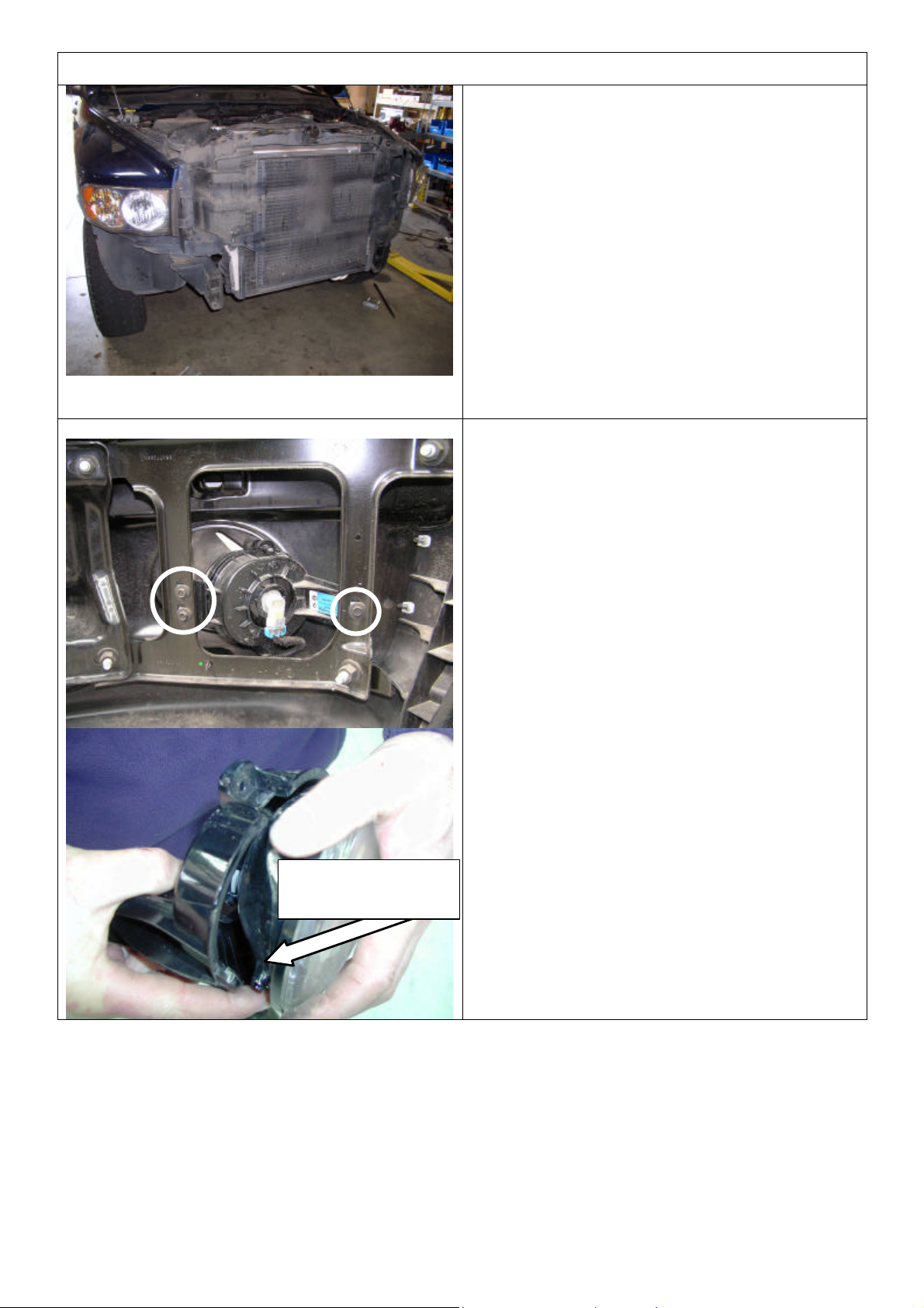
REMOVAL OF BUMPER
1. If fog lights fitted in bumper, undo fog light
loom connection (connection located on LHS
of bumper)
2. Remove bumper by undoing 4 x M12 nuts on
‘U’ bolts through chassis and withdrawing
bumper off chassis mount position, set aside.
Retain bumper retaining ‘U’ bolts and nuts.
Note: For 2500 turbo diesel shown (and 3500
TD), undo and remove intercooler top mount
bolts and rubber suspension blocks, this will
allow the intercooler to tip back at the top and
clear of the bumper U bolts allowing removal).
3. If OE fog lights fitted and are required for refitment into bull bar, remove each light and
bracket assembly and then remove lights as
shown by prising the lug each side from the
case and undoing the adjuster screw.
4. Also, if OE fog lamps are to be reused,
remove fog lamp loom fitted to bumper for reuse.
Prise open to
remove lug
Last Rev Date: 11-Sep-2006 Page 5 of 16 Fitting instructions# 3783239
Copyright © 2005 by ARB Corporation Limited. All rights reserved, this document must not be reproduced without the express authority of ARB Corporation Ltd
Page 6
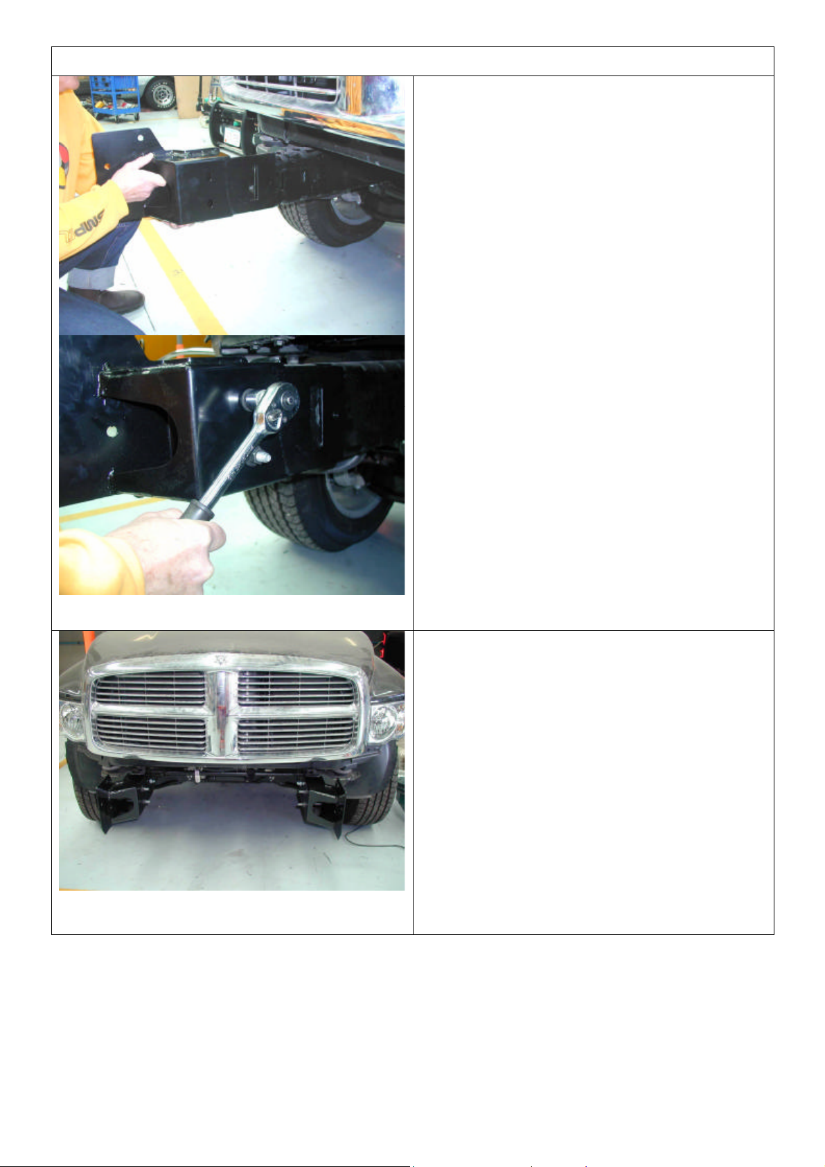
FITTING PROCEDURE GENERAL
FOR 1500 MODEL VEHICLES
FOLLOW STEPS 5 - 11, FOR 2500
AND 3500 VEHICLES STEPS 12 – 18.
5. Fit mount brackets to chassis rails and using
existing U bolt sets, refasten.
6. Bracket set on vehicle.
Last Rev Date: 11-Sep-2006 Page 6 of 16 Fitting instructions# 3783239
Copyright © 2005 by ARB Corporation Limited. All rights reserved, this document must not be reproduced without the express authority of ARB Corporation Ltd
Page 7
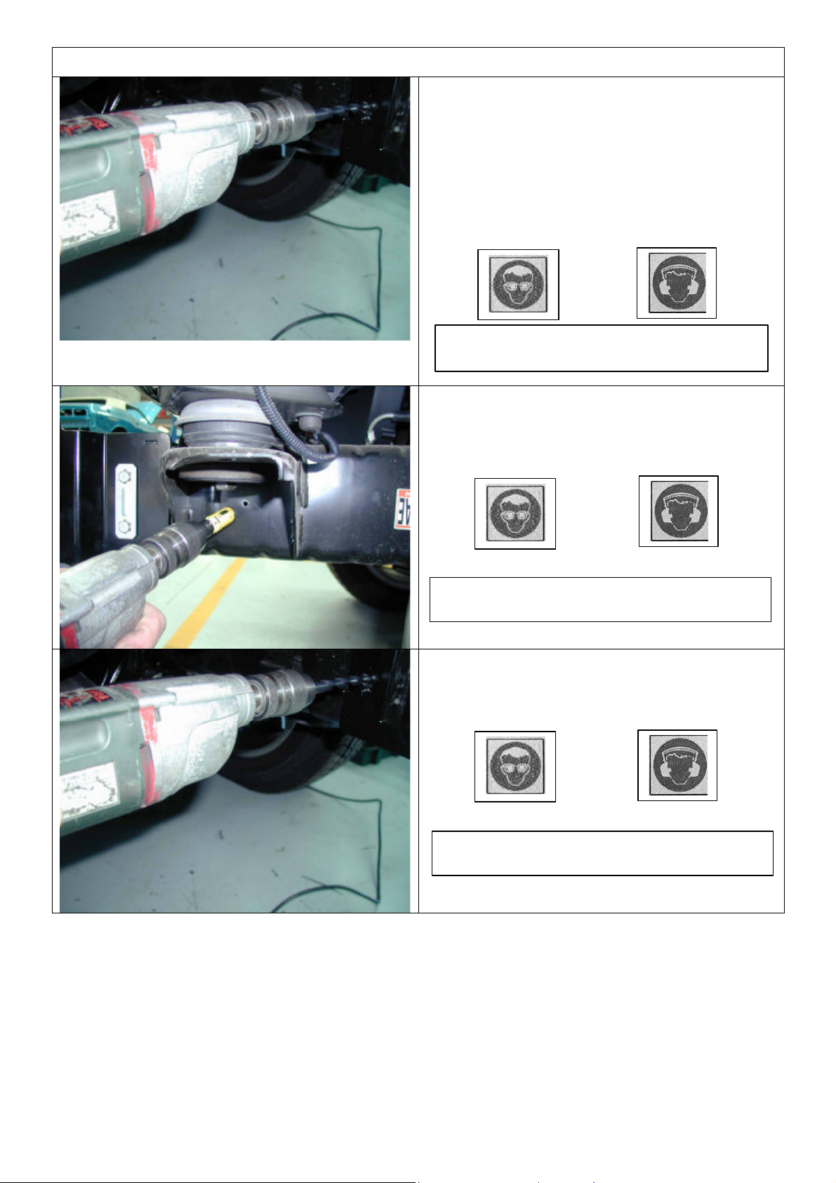
Warning: Drilling operations can result in flying
metal debris, safety glasses should be worn.
Warning: Drilling operations can result in flying
metal debri
s, safety glasses should be worn.
FITTING PROCEDURE GENERAL
7. Create a starter point with Dia 10.0mm drill
using pilot hole in mount bracket for
alignment. This will be a guide for Dia 7.0
through hole, which will in turn be used to
create a guide hole for Dia 19.0mm hole saw
Step 9.
8. Using the 7.0mm drill, drill right through both
sides of the chassis.
Warning: Drilling operations can result in
flying metal debris, safety glasses should be
9. Use the Dia 19.0 hole saw, as shown, with
7.0mm hole as a guide to drill a hole through
outer wall of chassis.
10. Then, as shown, using a Dia 10.0 drill, drill
hole through inner wall of chassis.
Last Rev Date: 11-Sep-2006 Page 7 of 16 Fitting instructions# 3783239
Copyright © 2005 by ARB Corporation Limited. All rights reserved, this document must not be reproduced without the express authority of ARB Corporation Ltd
Page 8
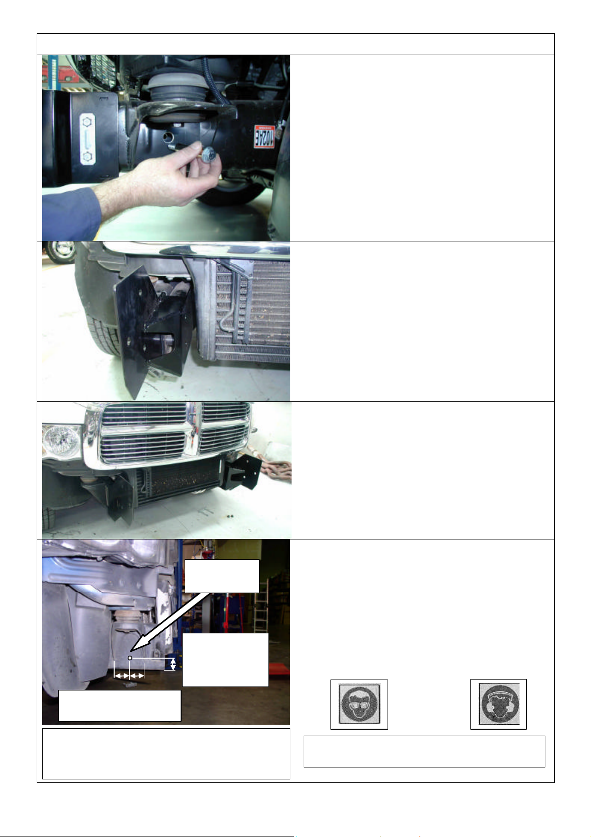
OF CHASSIS
BETWEEN FLANGES
Warning: Drilling operations can result in flying
metal debris, safety
glasses should be worn.
FITTING PROCEDURE GENERAL
11. As shown, fit M10x100 bolt, sleeve, M10 x
3mm washer and flange nut and do up tight.
Note: Bolt head and washer outboard as
shown, nut to be on inside face of bracket.
2500 AND 3500 ONLY STEPS 12 - 18
12. Fit chassis brackets as shown.
DRILL DIA
12.0mm
APPROX.
35mm FROM
UNDERSIDE
13. Insert original U bolts, entering from inboard
face of chassis (you may have to tilt
intercooler to gain sufficient clearance to
allow U bolt to enter this side).
14. Set brackets so front edge is vertical then do
bolts up tight.
15. Replace the intercooler suspension blocks
and bolts if removed for U bolt removal.
16. Mark the position for the pinning hole
centrally between the body mount bracket
flanges as shown on the outboard face of the
chassis rails.
17. Drill through both sides of chassis and mount
bracket flange Dia 10.0mm. **CAUTION
18. Fit M10 x 100 pinning bolt, M10 x 3MM
washer and flange nut set and do up tight.
LOCATE CENTRALLY
CAUTION: TAKE CARE NOT TO DRILL
THROUGH INTO THE RADIATOR ON
THE INSIDE OF CHASSIS.
Last Rev Date: 11-Sep-2006 Page 8 of 16 Fitting instructions# 3783239
Copyright © 2005 by ARB Corporation Limited. All rights reserved, this document must not be reproduced without the express authority of ARB Corporation Ltd
Page 9
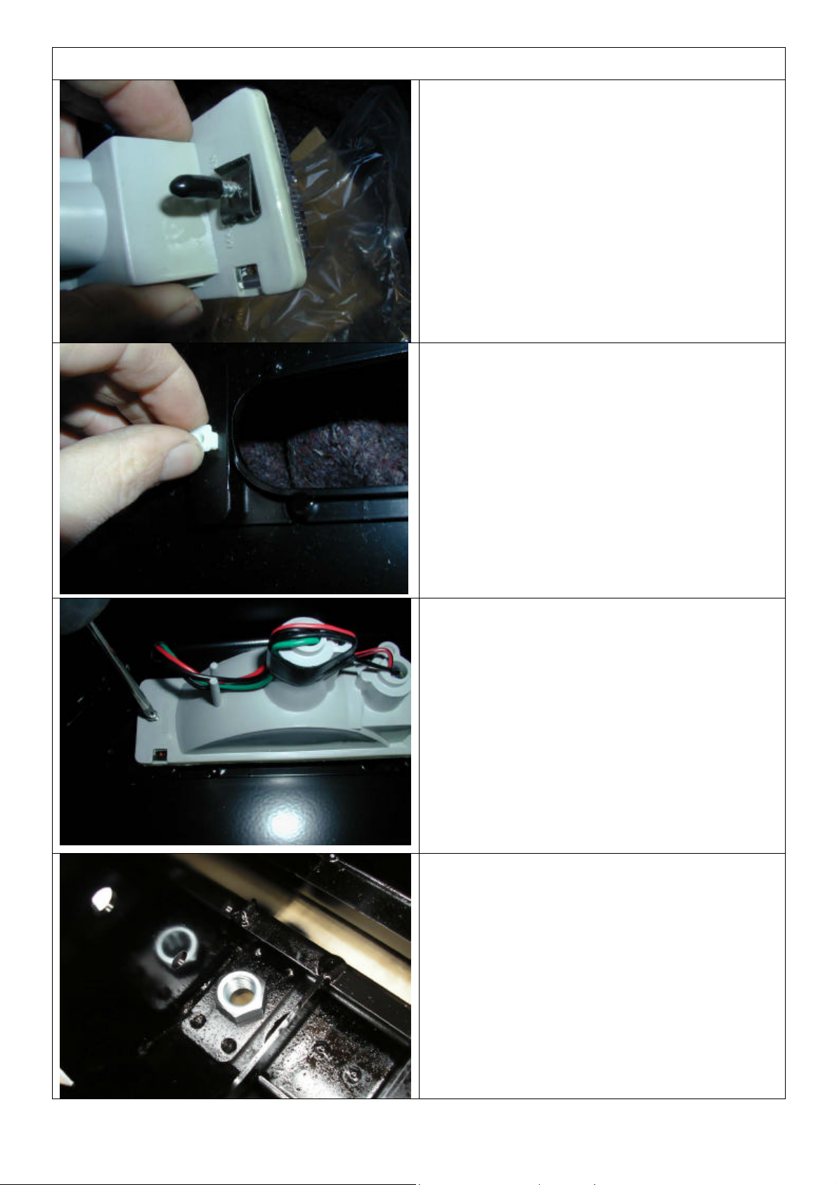
FITTING PROCEDURE GENERAL
19. Remove lights from cartons and then
remove screws and speed nuts from each
light. These fasteners are not to be reused –
new screws are supplied in the fitting kit
20. Insert nylon nuts into square holes in light
brackets inside wing area
21. Fit lights using screws supplied in fitting
kit, taking note of RH and LH light bodies,
they are different and must be placed on
the correct side of bull bar.
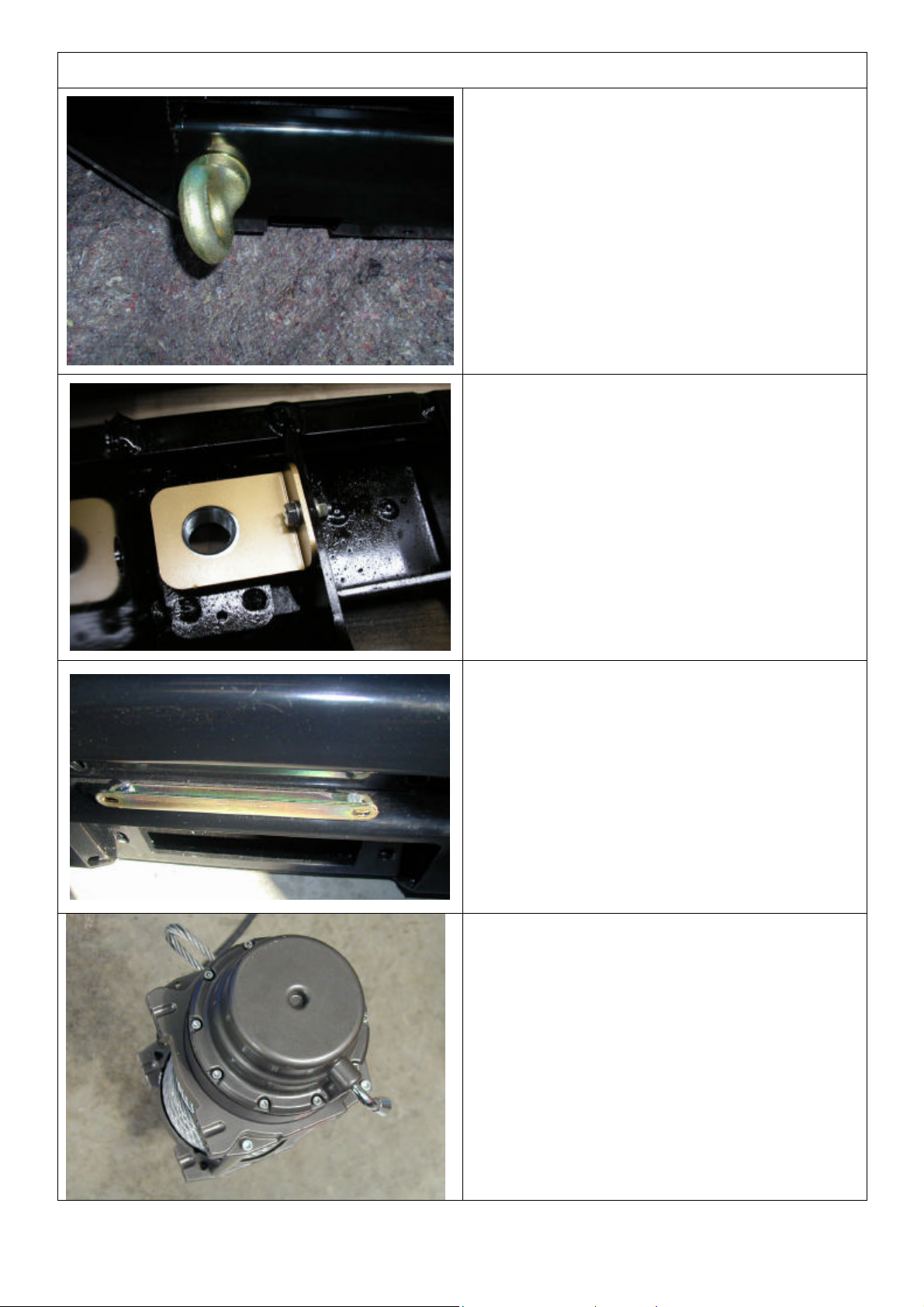
22. Fit large eyebolt nut into the plate on the
inside of the bar.
Last Rev Date: 11-Sep-2006 Page 9 of 16 Fitting instructions# 3783239
Copyright © 2005 by ARB Corporation Limited. All rights reserved, this document must not be reproduced without the express authority of ARB Corporation Ltd
Page 10
FITTING PROCEDURE GENERAL
23. Screw in the eyebolt using the large
washer. Eyebolt can be positioned to sit
vertically by rotating the large nut to the
correct position
NOTE: EYEBOLTS SHOULD BE REMOVED
FOR SAFETY REASONS WHEN
TRAVELLING ON PUBLIC ROADS.
24. When the large nut is in its final position,
secure with the nut retaining bracket
using an M6 bolt, washer and flange nut.
25. Secure the number plate bracket using
M6 bolts, flat washers and flange nuts.
Attach the longer side to the bullbar and
the shorter side to the number plate.
Note: As supplied from Warn, the winch handle
on 1500 and 16500lb winches should be in
the position as shown. This is correct
orientation for this bar.
26. Remove cable retaining band and position
cable loop so it will go through roller fairlead
when it is placed in bull bar.
Last Rev Date: 11-Sep-2006 Page 10 of 16 Fitting instructions# 3783239
Copyright © 2005 by ARB Corporation Limited. All rights reserved, this document must not be reproduced without the express authority of ARB Corporation Ltd
Page 11
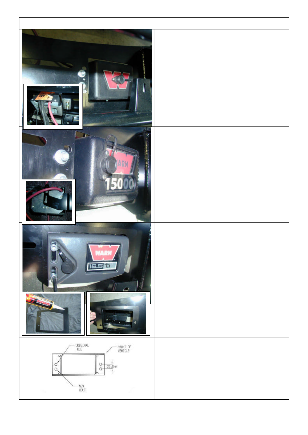
FITTING PROCEDURE WINCH
Fit control box to pan:
• For 9500-12000lb winches, use universal
control box bracket supplied, attaching to
rear of control box mount studs.
• Slide bracket flange under pan and align
with mount slots.
27. Fasten in position with 2 x M10 cap screws,
black washers and flange nuts
• For 15000lb winches, use Warn supplied
control box bracket, attaching to rear of
control box mount studs.
• Slide bracket flange under pan and align
with mount slots.
28. Fasten in position with 2 x M10 cap screws,
black washers and flange nuts.
• For 16500lb winches, apply Sikaflex (or
similar product) to rear of control box trim
plate from fitting kit (note orientation critical
to suit final position with control box profile
in pan opening).
• Position trim plate on top of pan centrally
about control box opening and line up with
mount slots.
29. Fasten in position with 2 x M10 cap screws
and flange nuts from fitting kit.
30. In some cases, the roller fair lead bracket
must have a second set of holes drilled to line
up with holes in winch bracket. If required,
mark out as shown and using a 13.0 mm drill
bit, drill two holes as shown in diagram.
Last Rev Date: 11-Sep-2006 Page 11 of 16 Fitting instructions# 3783239
Copyright © 2005 by ARB Corporation Limited. All rights reserved, this document must not be reproduced without the express authority of ARB Corporation Ltd
Page 12
FITTING PROCEDURE WINCH
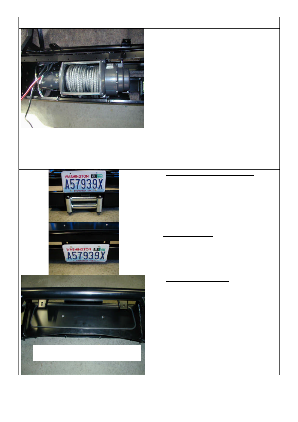
31. Viewed from front of vehicle the winch clutch
(handle) must be positioned on the LH side
(same side as smaller square access hole in
pan). Cable must spool from the bottom of
winch. Draw off enough cable so cable crimp
can be pulled through roller fairlead.
32. Bolt winch in position with the roller fair lead
in place.
Hint: To increase access to mount bolts in front of
roller fairlead, remove circlips from bottom of each
vertical roller shaft, push shaft up so roller can be
dislodged sideways. Do up bolts in fairlead and
winch, then refit circlip.
33. Connect the winch control box cables to the
winch motor. Refer to the Warn handbook for
additional information. Connect the long
winch + & - cables to the vehicle after the bar
is installed. Refer to the Warn winch
manual for vehicle wiring instructions.
34. Fitting number plate – with winch
Bolt number plate to the bracket with the M6 X
16mm bolts and M6 flange nuts through the
lower holes of the number plate.
If not fitting winch.
Bolt the number plate through the top holes
using M6 X 16mm bolts and M6 flange nuts.
35. If not fitting winch cont.
36. Wrap rubber extrusion around winch cover.
37. Place washers over the winch cover fixing
holes located on the top middle face of the
winch bumper.
38. Place the winch cover on top of the winch
bumper inline with the mount holes.
39. Bolt together using the M6 button head
stainless steel screws and M6 nuts.
View from above, rear of bull bar
Last Rev Date: 11-Sep-2006 Page 12 of 16 Fitting instructions# 3783239
Copyright © 2005 by ARB Corporation Limited. All rights reserved, this document must not be reproduced without the express authority of ARB Corporation Ltd
Page 13
Warning: Drilling operations can result in flying
metal debris, safety glasses should be worn.
FITTING PROCEDURE BAR ON VEHICLE
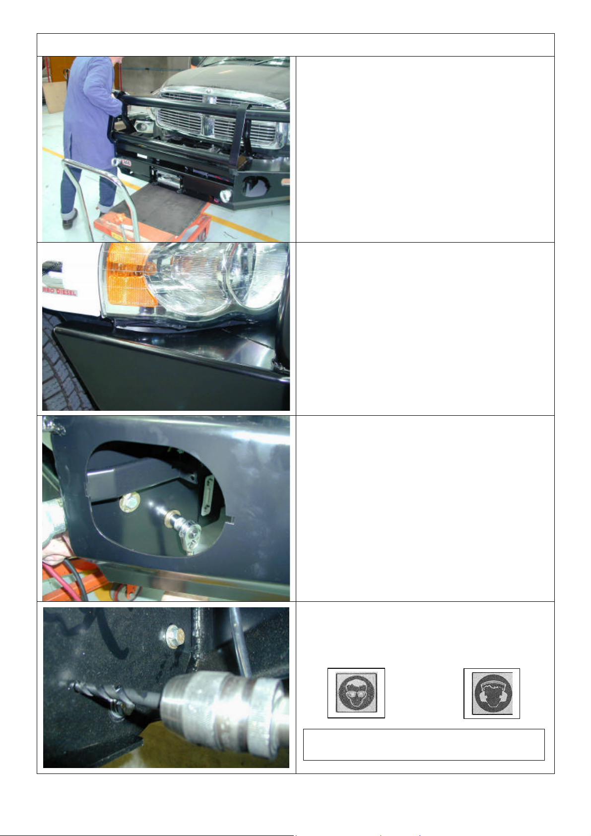
40. Using two people, three if winch fitted,
position the bar assembly on the vehicle
mounts.
Caution: This product is heavy, especially if a
winch is fitted. Do not attempt to lift it and fit it
by yourself. Have some assistants help you or
use a mechanical aid such as this hydraulic lift
table as shown.
40. Bolt the bar to the mounts using M12 bolts,
large flat washers and spring washers. Bolt
the bar to the mounts using M12 bolts, large
flat washers and spring washers. Align the
bar to the profile of the guards, grille and light
profile and tighten all bolts.
41. When bar is aligned, tighten bolts.
42. Using the M10 pilot holes in mount brackets,
drill pinning hole through uprights on bull bar.
Fit M10 screw, washer set and flange nut and
do up tight.
Last Rev Date: 11-Sep-2006 Page 13 of 16 Fitting instructions# 3783239
Copyright © 2005 by ARB Corporation Limited. All rights reserved, this document must not be reproduced without the express authority of ARB Corporation Ltd
Page 14
FITTING PROCEDURE BAR ON VEHICLE
If fitting optional accessory fog lamps kit
9381FCK follow fitting instructions supplied
with kit. If fitting OE fog lights follow steps 43 –
48.
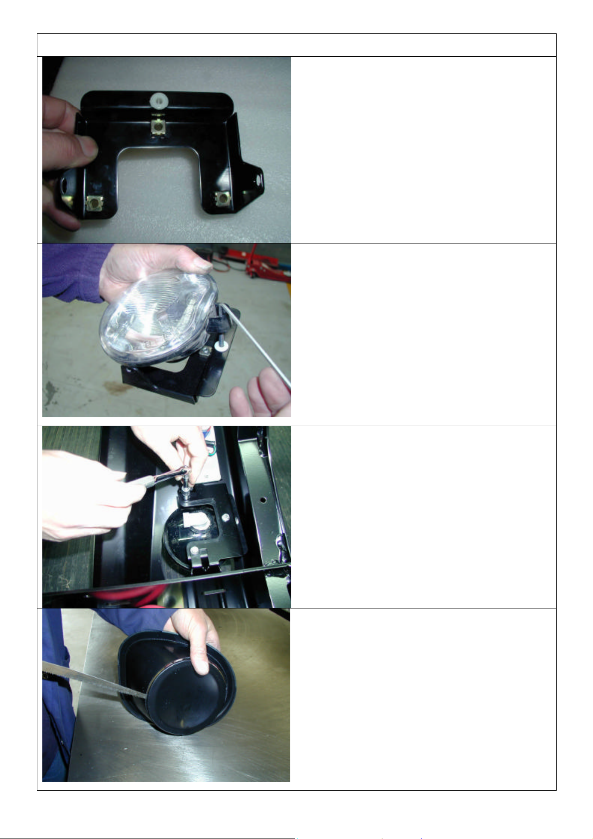
43. Fit M6 cage nuts and grommet to adaptor
bracket as shown.
44. Fit light to adaptor bracket by locating mount
lugs in light body into holes in adaptor bracket
flanges.
45. Screw adjuster into grommet so that light is
approximately parallel to bracket.
46. Fit adapter bracket and fog lamp assembly
into brackets in bull bar wings, as shown.
47. Bolt in place with M6 x 16 bolt and washer
sets into cage nuts.
48. Route OE fog lamp loom and connect to
lamps.
Fitting plastic fog lamp aperture moldings.
49. If fog lamps are fitted, cut centre panel out of
light aperture moldings using a hack saw
blade.
50. If fog lamps are not fitted leave centre panel
in place.
Last Rev Date: 11-Sep-2006 Page 14 of 16 Fitting instructions# 3783239
Copyright © 2005 by ARB Corporation Limited. All rights reserved, this document must not be reproduced without the express authority of ARB Corporation Ltd
Page 15
FITTING PROCEDURE BAR ON VEHICLE
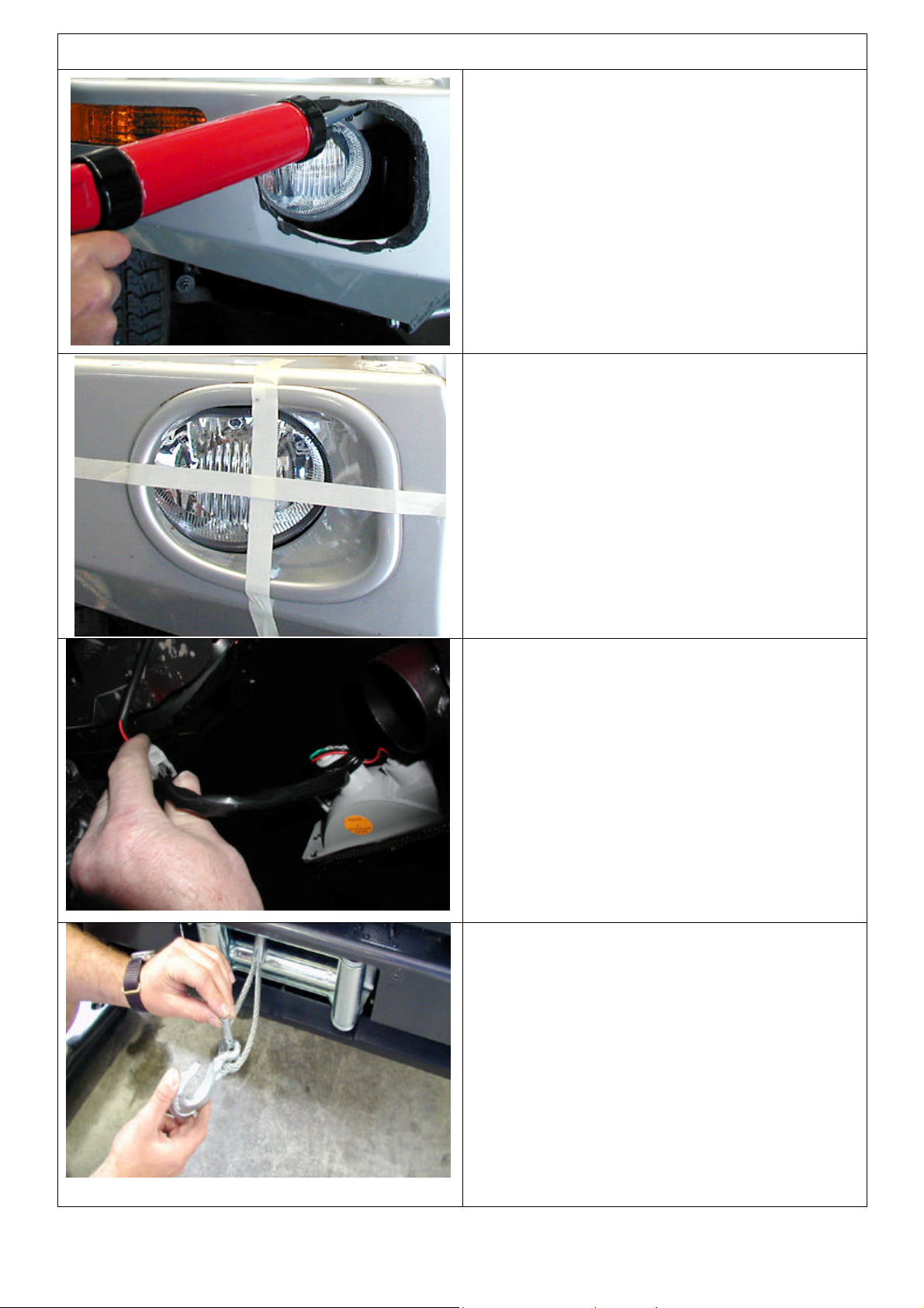
51. Note that the aperture moldings are handed
(RH or LH), select correct hand for each wing
aperture. Apply Sikaflex to recess in aperture
molding flange then fit to aperture in wing.
Use adhesive tape to secure plastic mold
while Sikaflex cures.
52. Use adhesive tape to secure plastic mold
while Sikaflex cures.
53. Wire up indicators and running lamps. Wire
loom extensions are supplied in fitting kit.
54. If winch fitted, fit off winch hook.
Last Rev Date: 11-Sep-2006 Page 15 of 16 Fitting instructions# 3783239
Copyright © 2005 by ARB Corporation Limited. All rights reserved, this document must not be reproduced without the express authority of ARB Corporation Ltd
Page 16
FITTING PROCEDURE BAR ON VEHICLE
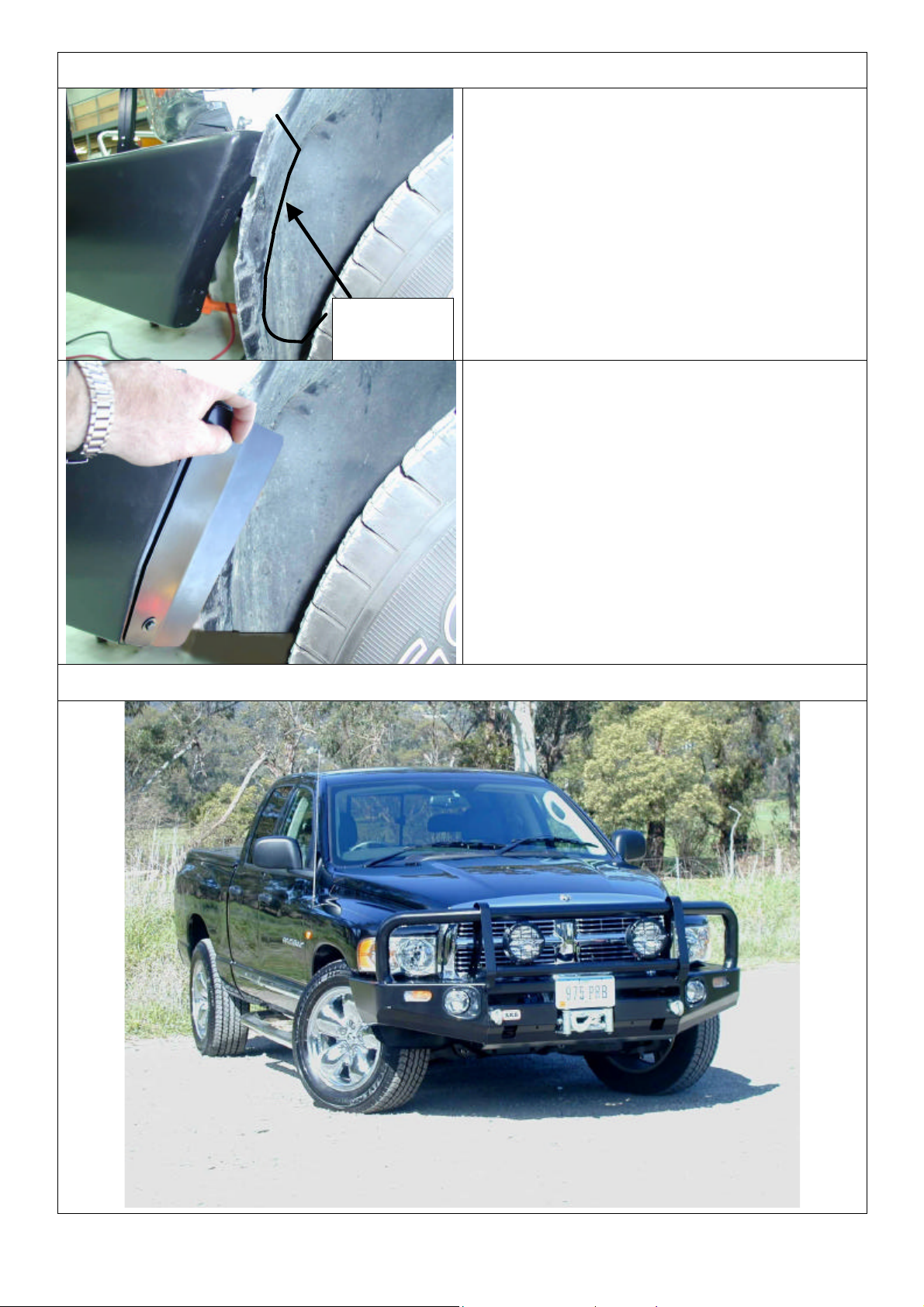
55. Trim fender liner with air hacksaw or similar
tool along line as shown. Cut away the
outboard flap, which normally fits in the end
of the bumper wing. This is so the liner can
be held back easily by the retaining bracket at
step 56.
Cut along
this path
56. Fit liner retainer bracket with black M6 bolt
and washer sets into M6 cage nuts in wing
returns each side as shown.
FITTED PRODUCT ON 1500 MODEL
Last Rev Date: 11-Sep-2006 Page 16 of 16 Fitting instructions# 3783239
Copyright © 2005 by ARB Corporation Limited. All rights reserved, this document must not be reproduced without the express authority of ARB Corporation Ltd
 Loading...