

Page 1
SYMPHONY
OWNER’S MANUAL &
INSTALLATION GUIDE
Note: Read all instructions before proceeding with installation.
All specifications are ± 1/4’’ and are subject to change without notice.
SERIES
Page 2

Page 3
TABLE OF CONTENTS
PRODUCT REGISTRATION INFORMATION 4
CONGRATULATIONS! 5
SAFETY INSTRUCTIONS 6
INSTALLATION INSTRUCTIONS
Pre-Installation Procedures 7
Electrical Installation 8
Structural Preparation 9
Framing Diagrams 10
Integrally Skirted Whirlpools 11
Flat Panel Skirt Installation 12-14
System Test and Clean-Up 15
OPERATION
Whirlpool Operations 16-18
MAINTENANCE AND CARE
Initial Cleaning 19
Whirlpool System Cleaning 19
Surface Cleaning 19
Jet Cleaning 19
Surface Scratch Removal 20
Repair Information 20
Water Quality Issues 20-21
TROUBLESHOOTING GUIDE
Symptoms/Possible Problems/Solutions 23
Serial Number - How to Locate 23
PARTS ORDER FORM/PARTS MAP/PARTS LIST
Parts Order Form 24
Parts Order Map 25
Parts Order List 26
AQUATIC LIMITED WARRANTY 27
Page 4
AQUATIC INDUSTRIES, INC.
Product Registration Information
Your product warranty is registered and confirmed with Aquatic through the Serial Number on
your unit. You do not need to contact Aquatic to confirm registration. Please fill out the information
below and reference when contacting the distributor to expedite warranty claims.
OWNER INFORMATION:
Model Name
Serial Number
(See Table of Contents for Location)
Purchase Date
Distributor
P.O. Box 889 • Leander, TX 78646-0889
Phone (800) 928-3707 • Fax (888) 296-7450
Aquatic Industries, Inc.
4
Page 5
CONGRATULATIONS!
You have chosen one of the finest bath products in the world! Aquatic Industries supports your purchase
with strong commitments to quality and customer satisfaction.
Please read and follow all of the instructions contained in this Owner’s Manual before installing, operating or
maintaining your whirlpool. In addition, you should continually refer to these instructions during the life of your
whirlpool. Failure to comply with these instructions may invalidate your warranty. If you have any questions
concerning installation, operation, maintenance or any other aspect of your whirlpool, please contact:
AQUATIC INDUSTRIES CUSTOMER SERVICE CENTER: 800-928-3707
(The Troubleshooting Guide on page 23 may be helpful in answering some of your questions.)
NOTE:
The installation and service of your whirlpool should be
performed ONLY by a qualified electrician, technician or plumber.
IMPORTANT!
This product MUST BE WATER-TESTED and inspected prior to installation
or warranty will be voided. See page 7 for instructions.
PLEASE CHECK ENTIRE UNIT FOR ANY DAMAGE.
If it appears damaged, contact your Aquatic Distributor immediately.
Aquatic Industries, Inc. warranty does not cover damage that occurs in transit.
Aquatic Industries, Inc.
5
Page 6

IMPORTANT SAFETY INSTRUCTIONS
WARNING: WHEN USING THIS UNIT, THESE BASIC PRECAUTIONS SHOULD BE FOLLOWED.
This manual contains information and instructions for proper operation and maintenance of your whirlpool. Failure to
follow these instructions could result in personal injury, electrical shock or fire.
READ AND FOLLOW ALL INSTRUCTIONS
DANGER! TO REDUCE THE RISK OF INJURY:
1. Do not permit children to use this unit unless they are closely supervised by an adult at all times.
Supervision is also required when whirlpool bath is used by an elderly or handicapped individual.
2. Use this unit only for its intended use as described in this manual. Do not use attachments not
recommended by the manufacturer.
3. Do not operate this unit without guard over the suction fitting.
4. The water in a whirlpool should never exceed 40°C (104°F). Water temperatures between 38°C (100°F)
and 40°C (104°F) are considered safe for a healthy adult. Use time should be limited to approximately
30 minutes, followed by a shower to cool down. Longer exposures may result in hyperthermia. The
symptoms of this condition are nausea, dizziness and fainting, which can be fatal. Lower water
temperatures are recommended for extended use (exceeding 10-15 minutes) and for young children.
5. Since excessive water temperatures have a high potential for causing fetal damage during the early
months of pregnancy, pregnant or possibly pregnant women should limit whirlpool water temperatures
to 38°C (100°F).
6. The use of drugs or alcoholic beverages before or during whirlpool use may lead to unconsciousness with
the possibility of drowning. Never use the whirlpool while under the influence of alcohol, anticoagulants,
stimulants, antihistamines, vasoconstrictors, vasodilators, hypnotics, narcotics or tranquilizers.
7. Persons with a medical history of heart disease, low or high blood pressure, circulatory system problems,
or diabetes should consult a physician before using a whirlpool.
8. Persons using medication should consult a physician before using a whirlpool since medication may
induce drowsiness while other medication may affect heart rate, blood pressure and circulation.
DANGER: To reduce the risk of injury, enter and exit the bath slowly.
WARNING: Never operate electrically connected devices in or near the bath. Never drop or insert any object into any
opening within the whirlpool.
This unit must be connected to a supply circuit that is protected by a Ground Fault Circuit Interrupter (GFCI). Such
a device should be installed by a licensed electrician and should be tested on a regular basis (at least monthly). To
test the GFCI push the TEST button. The GFCI should interrupt the power. Push the RESET button and the power
should be restored. If the GFCI fails to operate in this manner there is the possibility of an electric shock. DO NOT
USE. Disconnect the unit and have the problem corrected by a qualified service technician. To avoid the possibility
of personal injury and discoloration of the acrylic surface, the inlet water temperature should not exceed 60°C (140°F).
The bath should be drained after each use. Each bather should start their bath with fresh water.
CAUTION: DO NOT USE HARSH ABRASIVES OR SOLVENTS FOR CLEANING THIS UNIT.
INSTALLER/OWNER BEARS ALL RESPONSIBILITY TO COMPLY WITH ALL
STATE AND LOCAL CODES WHEN INSTALLING THIS PRODUCT.
SAVE THESE INSTRUCTIONS
Aquatic Industries, Inc.
6
Page 7
INSTALLATION
INSTRUCTIONS / GUIDELINES
READ ALL INSTRUCTIONS CAREFULLY BEFORE INSTALLATION
PRE-INSTALLATION PROCEDURES:
1. This whirlpool is factory-assembled, complete with motor, pump, controls and plumbing. DO NOT lift or support
unit using plumbing lines or any part of circulation system. DO NOT relocate or otherwise modify any part of the
factory-installed circulation system, as this may affect the performance or safe operation of the whirlpool and will
void all warranties.
2. Inspect whirlpool unit and circulation system carefully before installing. Water test the unit before installation. If any
damages or defects are observed, DO NOT INSTALL. Notify your dealer immediately.
TO TEST:
3. Fill the tub with hot water (approximately 1000 F) to the overflow and allow to stand for a few minutes.
4. Plug in pump cord and run pump for 10 minutes.
5. Inspect the tub completely. Any defect must be reported to Aquatic Industries, Inc. prior to installation in order to
6. Check to ensure that your installation will conform to all applicable codes and secure necessary permits. All electri-
7. This unit has been factory-tested prior to shipment for leakage and proper operation of the system. However,
Aquatic will not be liable for any defects or damages, including incidental or consequential damages that could
have been discovered or prevented by following these procedures for storage, handling and inspection.
PLACE THE TUB IN AN AREA WHERE IT MAY BE DRAINED AFTER TESTING.
have it covered by warranty.
cal and plumbing connections should be made by qualified electricians and plumbers.
in transit and handling, the half-unions on the suction and discharge ends of the pump may become loose. Make
sure these are hand-tight.
PRE-PLANNING ACCESS, PLUMBING AND ELECTRICAL INSTALLATION:
1. Sufficient clearance must be provided for access to service connections: motor, pump and electrical hook-ups.
(Minimum unobstructed access 16” x 16”)
A. Alcove Installation (with optional skirt): Access is provided by removing the skirt. To permit removal of skirt, allow
at least 6” clearance at both ends of tub: vanity, toilet, etc., must not obstruct skirt removal.
B. Island or Pier Installations: Provide access panel at motor end (see diagrams on page 9)
C. Sunken Installations: Provide access panel in floor or in ceiling below.
2. Drain/waste pipe stub must be located in wall or floor to match location of drain, waste and overflow
kit tee fitting. Provide a 6” x 12” box-out in sub-floor or slab (see diagrams on page 9).
3. When fittings (spout, handles, valves, etc.) are to be mounted on the unit, be certain that the hot and cold water copper
supply lines are located where there is ample room for mounting before setting the unit in place.
4. WARNING: When using electrical products, basic precautions should always be followed, including the
following:
A. DANGER: Risk of Electrical Shock. Connect only to a separate circuit protected by a Ground Fault Circuit
Interrupter (GFCI).
B. Connection. Electrical hook-up must be performed by a licensed electrician in accordance with local,
state and national electrical codes.
C. Access Panel Required. For built-in custom units, provide an access panel for servicing electrical
components (see Electrical Installation on page 8).
Aquatic Industries, Inc.
7
Page 8
INSTALLATION INSTRUCTIONS
ELECTRICAL INSTALLATION:
All local, state and national electrical codes must be observed by a licensed electrician in connecting power to the
Aquatic whirlpool.
When using electrical products, basic precautions should always be observed, including the following:
1. READ AND FOLLOW ALL INSTRUCTIONS.
2. Circuit: A separate circuit (not to supply any other electrical devices) is required as follows: For units
equipped with a pump motor only, a 110/120 VAC 15 Amp circuit is required. Wire coding is black [hot], white
[neutral] and green (or bare copper for ground).
3. GFCI: A Ground Fault Circuit Interrupter must be installed in the circuits which bring power to the
whirlpool; do not omit. To test the GFCI, push the test button. The GFCI should interrupt power. Push the reset
button. Power should be restored. If the GFCI fails to operate in this manner, there is a ground current flowing,
indicating the possibility of an electric shock. Do not use this unit. Disconnect the unit and have the problem
corrected by a licensed electrician before using.
4. Grounding: Motors have a three prong electrical plug requiring a black [hot], white [neutral] and
green wired circuit.
5. Bonding: A pressure wire connector is provided on the exterior of the motor within this unit to permit connection
of a No. 8 AWG solid copper bonding conductor between all electrical equipment, as needed to comply with local
requirements.
6. Wall Switch: A remote wall switch is required by many state codes. It must not be within 5 ft. (1.5 m) reach of a
bather while standing in the tub and it must be mounted at a height to be out of the reach of small children. The
remote switch should not be further than 10 ft. (3.0 m) away.
7. Integral On/Off Switch: For a Symphony whirlpool supplied with a motor that has an integral on/off switch -- Make
certain the air tube that is connected to the motor is also connected to the on/off button nipple under the deck in
order for the system to function.
Aquatic Industries, Inc.
8
Page 9
INSTALLATION INSTRUCTIONS
STRUCTURAL PREPARATION:
Framing and supports will vary according to the model and type of installation selected.
1. Plumbing Connections: (spout, handles, valves, etc.) should be made after unit is installed. When mounting
fittings on unit, drill holes from finished surface, using appropriate-sized hole saw with fine-tooth or abrasive grit
cutting edge.
2. When plumbing connections have been made, proceed with electrical hook-up (see Electrical Installation on page 8).
TYPES OF INSTALLATIONS:
*Installation dimensions should be taken directly from the bathtub. Do not support the weight of the tub by its rim.
Alcove: Requires a skirt. Models shown with skirts have optional removable skirts. Other models not shown require
a field built skirt, have an integral skirt, or no skirt is available.
1. a) Alcove Framing: Leveled 1” x 3” ledgers indicated height “LH” dimension (see Alcove Diagrams on
page 9). Use a 3’ level. Nail ledgers to studs.
Island -- All Models: Above floor; no wall contact.
Peninsula -- All Models: Above floor; one end at plumbing wall.
Sunken (Partial or Full) -- All Models: Flush mount or self-rimming.
b) Island, Peninsula, Sunken Framing: Construct framework as shown in Island Diagrams on page 10, with
inside (cutout) dimensions “IW” and “ID” and height dimension “DH”. (Full height framework required, even in
sunken installations.) Check framework for proper dimensions, squareness and plumb. Use a 3’ (minimum)
level.
2. a) Before moving unit into alcove or framework see and follow enclosed Electrical Installation instructions on
page 8. (Electrical and air tube hook-ups will be difficult to perform if unit is installed first.)
b) Models with leveling feet: The following procedure is recommended for pre-leveled bottoms: Lift unit by the
rim, place in alcove or framework. If necessary, shim feet until unit is completely resting on leveled ledges or
framework. Secure the unit by fastening the bottom feet to the subfloor with any construction adhesive caulk.
The use of cement mortar is suggested as a foundation bed between the floor and the bottom of the unit to
suppress noise and give the rock solid feel for the user.
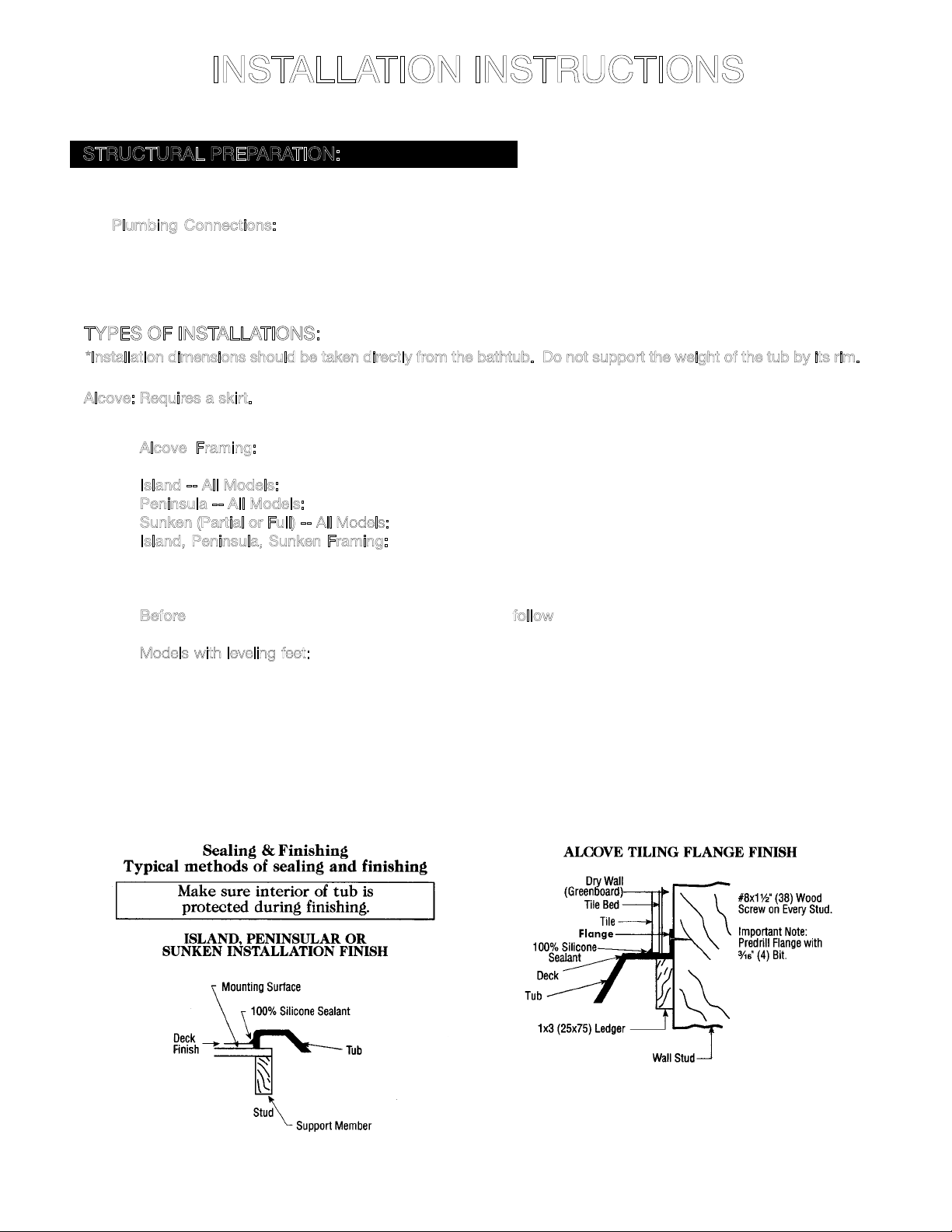
3. See and follow Sealing & Finishing diagrams (below) and System Test and Clean-Up on page 15.
Aquatic Industries, Inc.
(Not to support tub’s lip)
9
Page 10

INSTALLATION INSTRUCTIONS
ALCOVES
ISLANDS
Rectangular
Models
↔
Corner
Models
↔
A
Oval
Models
↔
Measurements should be taken directly from the tub.
DECK CUTOUT: A paper template will be enclosed with all
oval models. For the deck cutout, scribe on the deck two
center lines (a major and minor axis). Next, match the center
lines and trace the ellipse. Repeat this step three more
times. Once the tracing is complete, cut out the ellipse. The
dimensions should be exactly 2” smaller than the unit.
A - 6” x 12” (150 x 305)
Box-outs
B - Leveled Supports
1” x 3” (25 x 75) Ledgers
C - 12” x 18” (305 x 460)
Minimum Access
Aquatic Industries, Inc.
10
Page 11

INSTALLATION INSTRUCTIONS
INTEGRALLY SKIRTED WHIRLPOOLS:
Remove the shipping blocks of wood that are nailed along the back of the long 1 x 4 of the “H” frame.
1. To avoid obstructions during installation, make sure water lines, spout pipes and valve plumbing do not project into
alcove.
2. Ledger Strip: Fasten a 1” x 3” (25mm x 75mm) ledger strip along rear for alcove and along both sides in corner
installations at Dimension LH. (see diagram 6A)
3. Mix a 3 gallon bucket of cement mortar and water to a paste. Place three or four mounds of cement away from
drain hole in a line or square, approximately twice as high as the cavity under the tub bottom.
4. Place tub into alcove with front skirt firmly on floor and depress cement mounds. Make certain that back ledge of
tub rests firmly on ledger strip. (see diagram 6A)
5. Using 1 1/2” (40mm) galvanized roof nails or washer head screws: (a) spot-fasten the two bottom corners and the
two top corners of the vertical side nailing flanges. (b) Fasten at each stud through the top sides flanges and back flange,
working from both ends toward back center. (c) Complete fastening vertical side flanges.
6. When other than scratch coat is used, furring strips as thick as nailing flanges are recommended for installation on
studs above the installed Aquatic tub to assure drywall will be flush.
7. See and follow the Sealing & Finishing Diagram (diagram 6B) and System Test and Clean-Up on page 15.
6A 6B
REMOVABLE SKIRT PANEL FOR INTEGRALLY SKIRTED MODELS:
These models are offered with removable access panels. They provide a flush-to-wall installation (sheet rock overlaps
skirt while still providing access). The skirt features a decorative removable panel enabling easy access to motor, pump
and electrical hookups. IMPORTANT: Before installation of the panel, fill the unit, test the whirlpool system for proper
operation and check for leaks, then drain.
Integrally Skirted Acrylic Whirlpool
Framing
Dry Wall
Aquatic Industries, Inc.
Left Side Edge
Right Side Edge
Panel
Clips
(backside of panel)
11
Page 12

FLAT PANEL SKIRT INSTALLATION INSTRUCTIONS
PLEASE READ INSTRUCTIONS BEFORE PROCEEDING WITH INSTALLATION
NOTE: The skirt panel may require re-sizing to fit the specific installation. Carefully take your measurements so
that the skirt will fit the skirt opening. If re-sizing is required, it is suggested that the skirt is measured and marked
to the required dimensions. Cut to within 1/8” of finished dimensions using a fine tooth saw. Use a belt sander to
remove the remaining material to the finished size. The skirt could be damaged if improper procedures and/or tools
are used. It is important to follow all the steps in this installation procedure. If additional guidance is required, you may
contact the Aquatic Technical Department at (800) 928-3707.
PARTS INCLUDED FOR INSTALLATION:
4 - Spring clips
8 - #6, ½” self tap screws for spring clips
3 - #8, 1¾” stainless steel screws
(use 2 for 5’ skirts, 3 for 6’ skirts)
3 - Chrome decorative caps
3 - Brass decorative caps
3 - Decorative cap holders
9 - Decorative caps in assorted colors with attached cap holders
1 - Instruction sheet
If any of the above parts are missing from your package, contact Aquatic Technical Department at (800) 928-3707.
TOOLS REQUIRED FOR INSTALLATION: (NOT INCLUDED)
Phillips Head Screwdriver
Belt Sander
Fine-Tooth Saw
Wood Blocks
Pencil
Safety Glasses
Square/Level
Gloves
FLAT PANEL SKIRT INSTALLATION INSTRUCTIONS
1. Remove the wood strip (on some models) from the structural support. DO NOT REMOVE the structural support.
(SEE DETAIL VIEW A ON PAGE 13).
2. Locate the raised lip support channel beneath the lip of the bath tub as shown in FIGURE 1 ON PAGE 14. NOTE:
Some models do not have the lip support channel running the full length of the tub. These tubs will need to have
blocks of wood glued (construction cement) to the underside of the tub so that the spring clips can be attached.
3. Place the spring clips at even intervals along the support channel, use all four clips. Position the front of the clip
to line up with outside of the bath lip, (SEE FIGURE 4 ON PAGE 14) making sure they line up properly. Mark the
hole openings for the screws with a pencil. Place a #6, 1/2” screw at the marked position and secure the clips
to the channel. Use 2 #6 screws for each clip as shown in FIGURE 1. Make sure the screws go into the support
channel or into the wood blocks.
4. Slide upper side of skirt (SEE FIGURE 4) under the lip of the tub. Align the offset edge of the skirt so it is parallel
with the bottom of the bath lip (SEE FINAL ASSEMBLY DIAGRAM ON PAGE 14). The panel should slip into place
between the lip rim and the four spring clips (SEE FIGURE 4). While holding skirt at the bottom, move it inward
toward the tub (SEE FIGURE 2). The vertical edge of the skirt should be aligned perpendicular to the floor (SEE
FINAL ASSEMBLY DIAGRAM).
SEE FIGURE 2 AND FINAL ASSEMBLY. To secure the bottom of the skirt, wood blocks (2 for 5’ skirts or 3 for 6’ skirts),
will need to be anchored to the floor. Use a level (that is held against the outside face of the tub lip and touching the
floor) at each pre-drilled hole location to mark where the face of the skirt panel will be aligned. Subtract the thickness
of the skirt and the structural support to position the wood blocks. Anchor the blocks to the floor, then screw the 1¾”
#8 screws, through the decorative caps and the pre-drilled holes, into the wood blocks.
Aquatic Industries, Inc.
12
Page 13

DETAIL VIEW A
DETAIL VIEW B
Aquatic Industries, Inc.
13
Page 14

FIGURE 2
FIGURE 3
FINAL ASSEMBLY
* Base and plumbing may vary by model.
Aquatic Industries, Inc.
14
FIGURE 1
Page 15

INSTALLATION INSTRUCTIONS
CLEAN-UP:
1. Remove all construction residue and foreign materials. Wipe unit clean with a damp rag, otherwise staining may
occur.
2. Plaster may be removed by scraping with the edge of a piece of wood or rigid plastic. Do not use metal scraper.
For spots left by plaster or grout: rub lightly with a liquid detergent (Spic and Span or similar) on damp cloth or
sponge.
3. Do not use abrasive cleaners, scouring powders, steel wool, wire brushes or anything else that may harm or dull
the surface.
4. Paint, tar, or stubborn stains may be removed with rubbing alcohol. To avoid discoloration, cleaners containing
petroleum distillates must not remain on surfaces. NEVER use lacquer thinner or chlorinated solvents.
5. Dulled areas can be restored to a high gloss with white or a non-abrasive automotive rubbing compound, followed
by application of carnauba wax or white or cream automotive paste wax and buffing.
6. Remove minor scratches with 600 grit wet/dry sandpaper, followed by use of automotive rubbing compound and
paste wax, as above.
7. Major gouges require professional repair. Contact supplier to arrange factory-authorized repair services.
SYSTEM TEST:
1. Fill clean tub with water to a point no less than 2” above the highest jet, dirt left in tub may cause staining.
2. To test the Ground Fault Circuit Interrupter (GFCI), push the test button. The GFCI should interrupt power. Push
the reset button. Power should be restored. If the GFCI fails to operate in this manner, there is a ground current
flowing, indicating the possibility of an electric shock. Do not use this unit. Disconnect the unit and have the problem
corrected by a licensed electrician before using.
3. Push on/off button on the whirlpool unit.
4. Allow system to run a full 10-minutes.
5. Through access door or removable skirt, check for leaks in whirlpool plumbing system. Make sure half-unions at
both ends of pump are hand-tight. If leakage is occurring at any other points, notify distributor.
6. If any electrical malfunctions occur, consult electrician. Malfunctions of the pump/motor, whirlpool controls or
the circulating system should be reported to the distributor who supplied the whirlpool tub.
Aquatic Industries, Inc.
15
Page 16

OPERATION OF SYMPHONY
WHIRLPOOLS
JET OPERATIONS:
All Symphony Series jets are removable, and can simply be put into the dishwasher for easy cleaning. (Note: use top
rack and remove before drying cycle.)
SYMPHONY WHIRLPOOL JETS
The Symphony Series uses spinning back jets and directional jets to provide an invigorating hydrotherapy experience.
AQUATIC DIRECTIONAL JET:
• To adjust pressure
1. Grasp the outer ring of the jet.
2. Turn the outer ring counter clockwise to increase flow, clockwise
to decrease.
• To aim jet action
1. Simply push the jet nozzle to desired position.
• To remove jet
1. Grasp the outer ring of the jet.
2. Turn the jet counter-clockwise, until the jet clicks, then pull.
• To replace jet
1. Insert the jet into jet housing, pushing gently.
2. Turn the jet clockwise, past point of resistance, until the jet locks into
place.
(SEE DIAGRAM 10C)
(SEE DIAGRAM 10C)
(SEE DIAGRAM 10A)
(SEE DIAGRAM 10B)
:
:
:
:
AQUATIC SPINNING BACK JET:
10A
10B
10C
• To remove jet
1. Grasp the outer ring of the jet.
2. Turn the jet counter-clockwise, then pull.
• To replace jet
1. Insert the jet into jet housing.
2. Align notches with detents, push in gently.
3. Turn the jet clockwise, past point of resistance, until the jet locks into place.
Aquatic Industries, Inc.
16
(SEE DIAGRAM 10D)
(SEE DIAGRAM 10D AND 10E)
:
:
10D
10E
Page 17

OPERATION OF SYMPHONY
WHIRLPOOLS
WHIRLPOOL OPERATIONS:
Your whirlpool bathtub features a built-in circulating system that mixes the bath water with air and pumps the mixture
back into the bathtub creating the hydromassage action. Because it is a bathtub, it must be drained after each use.
The circulating system mixes air and water and must never be operated unless the bathtub is filled as described in the
section entitled “Before Your First Use.”
BEFORE YOUR FIRST USE:
• Make sure the bathtub is clean: If there are any residue or foreign materials left from
construction, clean the bathtub thoroughly. Use only the methods and materials described
in a later section entitled “Initial Cleaning” on page 19.
• Fill bathtub above jets: For your first “test run” use cold water. Fill the bathtub until the
water is at least 2” above the highest jet. Never operate the whirlpool unless water is at
least this high.
TO OPERATE YOUR WHIRLPOOL:
• ON/OFF BUTTON (see Diagram 11A): Models, so equipped, will have a button mounted
on the bathtub and may not have a wall mounted timer. Pushing the button forces a column
of air to a control which turns the pump motor on or off.
• GROUND FAULT CIRCUIT INTERRUPTER (GFCI): Test the GFCI as described in the prior
section “Electrical Installation” on page 8. This extra safety device is mounted either at the
remote power switch or in your home’s electrical panel. Push the test button. The GFCI
should interrupt the power. Push the reset button. Power should be restored. If the GFCI
fails to operate in this manner, there is a ground current flowing, indicating the possibility
of an electric shock. Do not use this product until the problem is corrected by a licensed
electrician.
• DIRECTIONAL JET NOZZLES (see Diagram 11B): The nozzle on each jet rotates freely
360°. You can adjust its position to concentrate the whirlpool action against a specific part
of the body or to adjust the overall whirlpool action in the bathtub.
Before the initial use of your whirlpool bath, be sure you have performed the “test run” described above, that you are
familiar with all the controls and switches and that the unit is operating properly. (See “Electrical Installation” on page 8.)
Be sure to keep all electrical appliances at least five feet away from the whirlpool bathtub.
11A
11B
1. Fill the bathtub with warm water. Water temperature must not exceed 104°F (40°C). Baths that are too hot can
be dangerous to your health. Also, water that’s too hot may cause discoloration and/or deform your whirlpool and
its circulating system.
2. If you will not be operating the whirlpool system during your bath, you may fill the bathtub to any comfortable level.
However, if you will operate the system, you must fill the bathtub as described in the prior section entitled “Before
Your First Use”. This will assure proper operation of the system and keep the jets from squirting water outside the
bathtub.
Aquatic Industries, Inc.
17
Page 18

OPERATION OF SYMPHONY
WHIRLPOOLS
WHIRLPOOL OPERATIONS (continued):
3. Do not operate the whirlpool system if:
• The bathtub is not filled to required levels above jets.
• You are pregnant (until you have consulted your doctor).
• You are taking medications or drugs that may make you drowsy.
• You are drinking any form of alcohol.
• You are using soap or bubble bath. This may cause over-foaming, collect in and eventually clog the system. It
is okay to use these after the whirlpool system has been turned off. Make sure to drain and rinse the bathtub
afterwards.
• You have just had a meal. Wait at least 30 minutes after dining.
• There is a child in the bathtub who may be unattended at any time. Never allow small children to remain
unattended in any bathtub.
• There are any small objects in the bathtub. The jet action can move small objects at high speeds, causing pain
and possible injury.
• The safety suction cover is not in place. The suction cover is the large fitting with a pattern of holes on its face,
mounted on the bathtub’s side wall.
• Your hair is loose and longer than shoulder length. If it is, secure it close to the head with pins or wear a shower
cap. Keep hair away from the suction cover.
• You are smoking. The heat of burning tobacco can damage the bathtub surface. Keep tobacco products and
ashtrays away from the bathtub.
4. Enter the bathtub. Sit back, stretch out, relax. Push the on/off button. You’ll feel water being pumped gently out
of the jets. Turn the jet nozzles to direct the air/water mixture against aching or tired limbs and muscles or adjust the
nozzles to create maximum whirlpool action in the whole bathtub. Adjust the volume of water by rotating the face
plate of directional jets, counterclockwise for more water, clockwise for less water.
Aquatic Industries, Inc.
18
Page 19

MAINTENANCE AND CARE
INITIAL CLEANING:
Before tub is used, the whirlpool system should be cleaned and disinfected. Remove all debris and clean tub before
putting whirlpool into service. DO NOT USE ABRASIVE CLEANERS ON THE ACRYLIC FINISH. Use a non-abrasive
detergent and rinse well after cleaning.
• Fill the tub with HOT water to a level 2” above the highest jet.
• Add 2 teaspoons of low-sudsing automatic dishwashing detergent and no more than 4 ounces of household
bleach to the water.
• Operate whirlpool for 10 minutes. Drain.
• Refill with cold water and operate whirlpool for 5 minutes. Drain.
WHIRLPOOL SYSTEM CLEANING:
To remove accumulations of bath residue from the whirlpool system, we recommend that you purge it at least twice a
month, or more depending on usage. To do this, follow this simple procedure. Fill the bath with hot water (not exceeding
140o F). Add to the hot water, 4 (6) tablespoons of low foaming detergent such as liquid Cascade or Calgonite and 24
(48) oz. of liquid household bleach, such as Clorox [use lesser amounts shown for 5-foot bathtubs, greater amounts
in parentheses for larger bathtubs]. Run the bath for 5 to 10 minutes. Drain the bath completely and refill with cold
water only. Run the whirlpool for 5 to 10 minutes, then drain the bath completely. Depending on the usage and/or the
content of the local water supply, more frequent purging may be necessary.
NOTE: DO NOT USE OIL OR OIL BASED BATH ADDITIVES.
If you want to use any kind of bath additive, use only a small amount of low-foaming powder or crystal substance; the
whirlpool action intensifies the foaming properties of soaps.
The use of certain bubble baths and bath additives may increase the level of accumulations of bath residue in the
whirlpool system. If excess accumulations persist, you should discontinue use of these products.
If you have followed the monthly purging instructions and still have an excess accumulation of bath residue and desire an
alternative cleaning mechanism, we recommend SUPER SYSTEMS CLEAN PLUS manufactured by Stearns Packaging
Corporation to rectify this condition. This may be obtained by calling Aquatic Industries, Inc. at (800) 555-5324. It is
recommended that you follow the instructions provided by the manufacturer with the product. Repeated use may be
necessary. SUPER SYSTEMS CLEAN PLUS does not replace the necessity to purge your whirlpool system at least
twice a month with a low foaming detergent and bleach.
SURFACE CLEANING:
Use common household, non-abrasive cleaners for most cleaning jobs. Rinse well and dry with a clean cloth. Never
use abrasive cleaners. Do not allow your Lucite® acrylic surface to come into contact with products such as acetone
(nail polish remover), nail polish, dry cleaning solution, lacquer thinners, gasoline, pine oil, etc. Remove dust with a soft,
dry cloth. Clean grease, oil, paint, and ink stains with isopropyl (rubbing) alcohol.
JET CLEANING:
All Symphony jets are easily removable, and can simply be put into the dishwasher for easy cleaning.
(NOTE: Use top rack and remove before drying cycle.)
S
Aquatic Industries, Inc.
19
Page 20

MAINTENANCE AND CARE
SURFACE SCRATCH REMOVAL:
Minor scratches may be removed by polishing your tub with a non-abrasive car polish, followed by buffing. Deeper
scratches can be removed by:
• Sanding with wet 400 grit sandpaper.
• Sanding with wet 600 grit sandpaper.
• Sanding with wet micro-grit sandpaper.
• Buff out using car polish.
REPAIR:
The installation and service of your whirlpool bath should be performed only by a qualified service technician.
Remember when contacting your dealer always have your serial number, proof of purchase and model number
available. This will ensure a quick response on warranty items.
The model and serial num bers are locat ed above th e pump on the b ackside of the whirlpool.
NOTE: ALL WARRANTY REPAIRS MUST BE AUTHORIZED BY AQUATIC BEFORE WORK IS STARTED. FOR SERVICE,
ALWAYS CONTACT YOUR DEALER.
CAUTION: Care should be taken to prevent inappropriate chemicals coming in contact with the Lucite® acrylic surface.
Please read and observe all instructions and/or warnings on containers containing substances you contemplate applying
to your whirlpool. Any failure to comply may void your warranty.
WATER QUALITY ISSUES:
Owners of fill and drain whirlpool bathtubs need to know basic information concerning water quality: how it affects
performance and enjoyment of the operation of their tubs, and steps that can be taken by the owner to correct related
problems. Important issues are the microbiological and chemical quality of the water.
MICROBIOLOGICAL QUALITY:
Microbes are present in water supplied by individual wells or water systems and even in the air around us. These
microbes are usually in amounts below what is noticeable. Microbes from the water or air or from a bather’s body may
settle on wetted surfaces such as a whirlpool bathtub’s surface or piping systems where they can grow in numbers
where we can notice them. With regards to whirlpool bathtubs, brown/black fungi/mold or pigmented (colored) bacteria
can be noted.
Fungi/Mold- Fungi and mold are always present. The levels are usually such that we do not notice them. When
moisture and temperature are sufficient, the organisms will grow to levels that we may smell and/or see. The best
example of such growth is the very common black growth on the bottom of shower curtains. The best solution to keep
these surfaces free from growth is frequent cleaning.
Pigmented Bacteria- Water utilities from all over the United States have experienced calls from consumers inquiring
and complaining about pinkish substance on bathroom fixtures that is very persistent, appearing in the shower, sink and
along the water line of toilet bowls. With whirlpool bathtubs, the formation of this colored substance may be particularly
pronounced in white tubs. The residue is less likely a problem associated with water quality than with naturally occurring
airborne bacteria. The bacteria may produce a pinkish film, and sometimes a dark gray film, on surfaces that are
regularly moist, including toilet bowls, shower heads, sink drains, and tiles. The problem is more common in humid
areas of the country. In any particular case, the determination of the exact species of bacteria causing the problem
would require lengthy and costly laboratory testing; however, most experts believe the bacteria responsible is Serratia
marcescens. These bacteria thrive on moisture, dust and phosphates, and are widely distributed in soil, food and also
in animals. The American Water Works Association suggests that short of buying pink fixtures, the best solution to
keep these surfaces free from the bacterial film is continual cleaning. The AWWA recommends a chlorine containing
the compound as the best cleaner and avoiding abrasives to avoid scratching fixtures, which will make them more
susceptible to bacteria.
Aquatic Industries, Inc.
20
Page 21

MAINTENANCE AND CARE
WATER QUALITY ISSUES (continued):
CHEMICAL QUALITY:
The water supplied by individual wells or water systems always contains chemicals, usually in amounts below those
which the consumer would notice. Examples of such chemicals, which are of potential concern for the owners of fill
and drain whirlpool bathtubs, are calcium and magnesium salts, copper, iron, manganese and sulfates. When these
chemicals are present in sufficient amounts, they may cause problems in whirlpool bathtubs. You should contact your
water supply or treatment company and follow their suggestions for treatment.
Calcium and Magnesium Salts- Collectively, the various compounds of calcium and/or magnesium are referred to as
salts. Calcium and magnesium salts are often found in ground water supplies and cause “hardness” in water. Hard
and soft water are relative terms. Hard water retards the cleaning action of soaps and detergents, causing expense
in the form of extra work and cleaning agents. When hard water is heated, it will deposit a hard scale. With regard
to whirlpool bathtubs, high calcium and/or magnesium levels may result in the formation of white stains and scale
formation on the inside of the tubs, especially noticeable with colored tubs. If this occurs, you need to contact the water
supplier to determine the calcium and/or magnesium content and/or corrosion potential of the water and follow their
suggestions for treatment. If you are on an individual well, you need to contact a water treatment company to test your
water and suggest solutions if a problem is present.
Iron- Iron is found in many natural waters especially from wells. Iron in water can also result from the corrosion of piping
in the water supply system, such as cast iron mains or galvanized steel service lines, or galvanized piping in the home
water system. High iron levels may result in the formation of brown stains in the vicinity of the faucet outlets of various
fixtures in the home. With whirlpool bathtubs, the staining may be particularly pronounced because the aeration action
can oxidize iron to a form that settles out on the inside of the tubs, especially noticeable in white tubs. If high iron in
the water is present, you can also notice rust colored deposits in your toilet tank or dishwasher. If this occurs, you
need to contact the water supplier to determine the iron content and/or corrosion potential of the water and follow their
suggestions for treatment. If you are on an individual well, you need to contact a water treatment company to test your
water and suggest solutions if a problem is present.
Manganese- Manganese is found in many natural waters, especially from wells. High manganese levels may result
in the formation of small black particles that can stain laundry, especially noticeable with whites such as sheets or
towels. With whirlpool bathtubs, the formation of small black particles may be particularly pronounced because the
aeration action in the tub can oxidize manganese to an insoluble form that is especially noticeable with white tubs. If
high manganese in the water is present, you may also notice black stains on white laundry. If this occurs, you need to
contact the water supplier to determine the manganese content of the water and follow their suggestions for treatment.
If you are on an individual well, you need to contact a water treatment company to test your water and suggest
solutions if a problem is present.
TREATMENT:
If you have contacted your water supplier and followed its instructions and you are still having problems, you need to
increase the frequency of applications of low-foaming detergent/bleach starting from bi-monthly purging down to using
it every other day as required to eliminate your particular problem.
The use of certain bath oils, bubble baths and bath additives may increase the level of accumulations of bath residue
in the whirlpool system. More frequent cleaning may be necessary if these products are used in the whirlpool tub. If
excess accumulations persist, you should discontinue use of these products.
If you have followed the monthly purging instructions and still have an excess accumulation of bath residue and
desire an alternative cleaning mechanism, we recommend SUPER SYSTEMS CLEAN PLUS manufactured by Stearns
Packaging Corporation to rectify this condition. This may be obtained by contacting Aquatic Industries at (800) 555-
5324. It is recommended that you follow the instructions provided by the manufacturer with the product. Repeated
use may be necessary. SUPER SYSTEMS CLEAN PLUS does not replace the necessity to purge your whirlpool
system at least once a month with a low foaming detergent and bleach.
Aquatic Industries, Inc.
21
Page 22

WHIRLPOOL USER INFORMATION
PLEASE NOTE:
The air bath action may cause even small amounts of bubble bath or shampoo to foam excessively. Exercise
moderation in experimenting with different soap products.
No servicing of this product should be done by the user. There are no user serviceable parts. All controls
are located in the control recesses on the lip of the tub. These are the only controls that should be used by
the consumer. Do not change or alter any of these controls under any circumstances.
Motors are self-lubricating -- No lubrication required.
FCC CONSUMER INFORMATION
Electrical installation information listed on page 8.
This equipment generates and uses radio frequency energy and if not installed and used properly, that
is, in strict accordance with the manufacturers instruction, may cause interference to radio and television
reception. It has been type tested and found to comply with the limits for a class B computing device
in accordance with the specifications in subpart J of part 15 of the FCC rules, which are designed to
provide reasonable protection against such interference in a residential installation. However, there is
no guarantee that interference will not occur in a particular installation. If this equipment does cause
interference, which can be determined by turning the equipment on and off, the user is encouraged to
try to correct the interference by one or more of the following measures:
• Reorient the receiving antenna.
• Relocate the receiver with respect to the bath tub.
• Move the receiver away from the bath.
• Plug the receiver into a different outlet so that the receiver and bath are on different branch
circuits.
• If necessary, the user should consult the dealer or an experienced radio/television technician for
additional suggestions.
• The user may find the following booklet prepared by the Federal Communications Commission
helpful: “How To Identify and Resolve Radio-TV Interference Problems.”
This booklet is available from the U.S. Government Printing Office, Washington, DC 20402, Stock
No., 004-000-00345-4.
Aquatic Industries, Inc.
22
Page 23

TROUBLESHOOTING GUIDE
WARNING: Always turn off power at the main electrical service panel when servicing your whirlpool.
SYMPTOMS
Motor does not start 1) GFCI or circuit breaker in OFF position. 1) Reset GFCI
2) Fuses blown or thermal overload open. 2) Contact your electrician.
3) Locked motor shaft. 3) Contact Aquatic Industries, Inc.
4) Motor windings burned out. 4) Contact Aquatic Industries, Inc.
5) Defective starting switch inside 5) Contact Aquatic Industries, Inc.
single-phase motor.
6) Disconnected or defective wiring. 6) Check and reconnect if needed.
7) Low voltage. 7) Contact your electrician.
Motor does not reach full 1) Low voltage. 1) Contact your electrician.
speed. 2) Motor windings connected for 2) Contact Aquatic Industries, Inc.
wrong voltage.
3) Wiring too small. 3) Contact your electrician.
Motor overheats 1) Low voltage. 1) Contact your electrician.
(protector trips) 2) Motor windings connected for 2) Contact Aquatic Industries, Inc.
wrong voltage.
3) Inadequate ventilation. 3) Refer to installer/dealer.
4) Wiring too small. 4) Contact your electrician.
Pump delivers no water 1) Jets are closed. 1) Open jets.
2) Leakage of air into suction system. 2) Check suction screen for clogs.
3) Impeller clogged. 3) Clean and unplug.
Low pump capacity 1) Suction or discharge line partly plugged. 1) Clean and unplug.
2) Pump running at reduced speed. 2) See “Motor does not reach full speed.”
3) Impeller clogged. 3) Clean and unplug.
Noisy pump and motor 1) Worn motor bearings. 1) Contact Aquatic Industries, Inc.
2) Pumps touching a stationary object. 2) Refer to installer/dealer.
3) Suction line partly plugged. 3) Clean and unplug.
4) Pump not supported properly. 4) Contact Aquatic Industries, Inc.
Leakage of water at shaft 1) Shaft seal requires replacement. 1) Contact Aquatic Industries, Inc.
POSSIBLE PROBLEMS
SUGGESTED SOLUTIONS
Leaking unions 1) O-ring missing or damaged. 1) Contact Aquatic Industries, Inc.
2) Loose unions. 2) Tighten unions.
Vibration noise 1) Tub or tub plumbing is touching tile/wall. 1) Refer to installer/dealer.
2) Pump is touching framing. 2) Refer to installer/dealer.
Model Number &
Serial Number Location
The tub model and serial numbers are located
above the pump area on the backside of the bathtub.
Your installer should have a service access panel
in this location.
Aquatic Industries, Inc.
23
Page 24

REPLACEMENT PARTS ORDER FORM
FOR SYMPHONY SERIES
How To Use:
1. Find your part on the map and make note of its number & letter.
2. Using map number and letter, choose part number and select color (or finish)
on Parts List provided on page 25.
3. Fill out the form below with the selected information. Fax or send to Aquatic.
4. Call Aquatic for parts pricing and shipping charges.
IMPORTANT!
The following information must accompany your order:
Serial Number, Model Number/Name, Purchase Date and Color
PLEASE FILL OUT COMPLETELY:
SHIP TO:
Name
Company
Address
City State Zip
Phone Fax
Serial # ________________________________ Model Name__________________________________
Model #_____________________ Color___________________ Purchase Date ________________
Quantity Part No. Description Color/Finish Price
BILL TO:
Name
Company
Address
City State Zip
Phone Fax
Mail orders to:
AQUATIC INDUSTRIES, INC.
P.O. Box 889 • Leander, TX 78646-0889
Phone (800) 928-3707 • Fax (888) 296-7450
Page 25

3c & d. Jet
Body with
Wall Fitting
11.
(Option)
SYMPHONY
REPLACEMENT PARTS ORDER MAP
3a. Directional
Jet
Part 7b.
Spinning
Back Jet
Part 7c. Gasket
12.
(Option)
2a. On/Off Air Button
2b. Air Button Assembly
Part 7a.
Jet Body
1a. Suction Cover
8 a. Air Check Valve
1b. Suction Wall Fitting
1c. Suction Elbow
1b.
1c.
13b.
13a.
(option)
13b.
13c.
Part 7d. Elbow
4a. .80 HP Pump
5a. Safety Suction
Valve
6a. Pump Base
13d.
9.
(Option)
Aquatic Industries, Inc.
13c.
13f.
25
Page 26

SYMPHONY
REPLACEMENT PARTS LIST
DESCRIPTION PART # COLOR/FINISH
1a. Suction Cover 8152HVSUCVRXX* Specify Color
1b. Suction Wall Fitting 8414FTG *****
1c. Suction Elbow 8412FTG *****
2a. On/Off Air Button 8115BUTTNXX* Specify Color
2b. Air Button Body 8115BODY *****
3a. Directional Jet 1058 White
3a. Directional Jet 1059 Bone
3a. Directional Jet 1060 Biscuit
3a. Directional Jet 1061 Black
3a. Directional Jet 1062 Sterling Silver
3a. Directional Jet 1063 Clear
3c&d. Jet Body with Wall Fitting 1056 White
3c&d. Jet Body with Wall Fitting 1057 Clear
4a. .80 HP Pump 8078MOTOR *****
5a. Safety Suction Valve 8150BSAFETY *****
6a. Pump Base 4618BASE *****
7a. Jet Body 8025JETBDY *****
7b. Spinning Back Jet 8475ROTJETXX *****
7c. Gasket 8025GASKET *****
7d. Elbow 8841FTG (right) *****
8840FTG (left)
8a. Air Check Valve 8441FTG *****
9. Bolt-On Grab Bar (option) 901806GRAB White
Bolt-On Grab Bar 901807GRAB Biscuit
Bolt-On Grab Bar 901240GRAB Chrome
Bolt-On Grab Bar 901220GRAB Brass
Bolt-On Grab Bar 901260GRAB Satin Nickel
Bolt-On Grab Bar 901270GRAB Polished Nickel
Bolt-On Grab Bar 901210GRAB Gold
Bolt-On Grab Bar 901805GRAB Oil Rubbed Bronze
11a. Lift and Turn Waste & Overflow (option) 93CPDWO Chrome
Lift and Turn Waste & Overflow 93PBDWO Brass
Lift and Turn Waste & Overflow 93SNDWO Satin Nickel
Lift and Turn Waste & Overflow 93PNDWO Polished Nickel
Lift and Turn Waste & Overflow 93PGDWO Gold
Lift and Turn Waste & Overflow 93ORBDWO Oil Rubbed Bronze
12a. Geberit Cable Drive Waste & Overflow (option) --- Specifiy Color
13a. Maint. Heater (Stainless Heat Tube) (option) 8095THEAT --13b. 2pc. Heater Split Nut --- --13c. Gasket / O-Ring --- --13d. 1.5 in. x 1in. Tailpiece --- ---
13f. 1.5 in. Tailpiece 8417SPIGOT ---
* To indicate color, replace “XX” with “WH” for White, “BO” for Bone, “BK” for Black, “ST” for Sterling Silver, “BI” for Biscuit, “CL” for Clear and “BR”
for Oil Rubbed Bronze.
Aquatic Industries, Inc.
26
Page 27

Aquatic Industries, Inc. Limited Warranty
For Symphony Series Whirlpools
Limited Warranty For Original Consumer For Household Usage
WHAT PRODUCTS ARE COVERED
Structures and surface finishes on Whirlpools (“Whirlpools”) and Soaking Tubs (“Tubs”), and their support equipment, components, attachments, controls and plumbing
equipment. Different warranty periods apply to specific components.
10 YEAR STRUCTURAL WARRANTY FOR WHIRLPOOL/TUB SHELL
Warranty Periods for Specific Components
Aquatic Industries, Inc. extends to the original consumer purchaser of the acrylic, fiberglass reinforced shell of a Symphony Series Whirlpool a limited warranty that
the shell will retain its structural integrity and configuration and be free of water loss due to a defect in the tub shell for a period of 10 years from the date of purchase,
but never more than 11 years from date of manufacture. This limited structural warranty does not apply to attachments to the acrylic, fiberglass reinforced shell, such
as plumbing, fittings and other apparatus; these pieces are covered below in a 2 Year Warranty.
10 YEAR SURFACE WARRANTY FOR FACE OF WHIRLPOOL/TUB
The interior surface/face of a Symphony Series Whirlpool is warranted against fading, blistering, cracking and delamination due to defects in the surface materials for a
period of 10 years from the date of purchase, but never more than 11 years from date of manufacture. This surface warranty extends to defects due to surface material
mixing or molding. This surface warranty does not apply to fading, cracking, delamination or blistering due to
2 YEAR EQUIPMENT WARRANTY FOR SUPPORT EQUIPMENT, COMPONENTS, CONTROLS & PLUMBING EQUIPMENT
All support equipment, components, controls and plumbing equipment on the Symphony Series Whirlpools are warranted for 2 years from date of purchase, but not
more than 3 years from date of manufacture, against defects in workmanship and materials. Pump seals, “O” rings, light bulbs, fuses and pillows are not included in this
two-year period. However, these accessories are warranted to be free from defects in materials and workmanship at the time of delivery to the original purchaser. Limited
labor is covered for 2 years from purchase, but never more than 3 years from date of manufacture, for limited labor on the support equipment, controls, or plumbing.
EXCLUSIVE REMEDY
Aquatic Industries, Inc. will, at its option, repair or replace (without removal or installation) the affected components of any defective Unit or System; repair or replace
(without removal or installation) the entire defective Unit or System; or refund the then-current list price of the Whirlpool or Tub. In all cases, a reasonable time period
must be allowed for warranty repairs to be completed.
WHAT YOU MUST DO
In order to make a claim under these warranties:
1. You must be the original consumer purchaser of the Whirlpools or Tubs.
2. You must promptly notify us within the warranty period of any defect and provide us with any substantiation that we may reasonably request.
Write to: Aquatic Industries, Inc. P.O. Box 889 Leander, TX 78646.
3. The whirlpools and tubs must have been installed and maintained in accordance with good industry practice and the specific Aquatic Industries, Inc. directions
contained in the Owner’s Manual and Installation Guide. Write for one if you don’t have one!
EXCLUSIONS
These warranties do not extend to or do not cover defects caused by:
1. Shipping damage by carriers or installation errors.
2. Accident, acts of God, abuse or misuse.
3. Unreasonable use (including any use for non-bathing purposes or failure to provide reasonable and necessary maintenance as specified in Aquatic Industries, Inc.
Owner’s Manual and Installation Guide supplied with the Whirlpool or Tub).
4. Any alteration, customization, or modification of the Whirlpool/Tub or its components.
excessive wear, sun fading or scouring due to cleaning.
LIMITATIONS
1. AQUATIC INDUSTRIES, INC. whirlpools and tubs sold for industrial, commercial or hotel use are warranted for two years, but not more than 3 years from
date of manufacture, with a limited warranty that the shell will retain its structural integrity and configuration and be free of water loss due to a defect in the tub
and the interior surface/face of the whirlpool/tub is warranted against fading, blistering, cracking and delamination due to defects in the surface materials. All
support equipment, components, controls and plumbing equipment and limited labor on the support equipment, controls, or plumbing are warranted for 1 year,
but not more than 2 years from date of manufacture. Pump seals, “O” rings, light bulbs, fuses and pillows are not included in this two-year period. However,
these accessories are warranted to be free from defects in materials and workmanship at the time of delivery to the original purchaser.
2. In all cases, AQUATIC INDUSTRIES, INC. reserves the right to fully satisfy its obligations under the Limited Warranties by refunding the then-current list
price of the defective Whirlpool or Tub (or, if the Whirlpool or Tub has been discontinued, of the most nearly comparable current product).
3. AQUATIC INDUSTRIES, INC. reserves the right to furnish a substitute or replacement component or product in the event a Whirlpool or Tub or any component of
these products is discontinued or otherwise unavailable.
4. THESE WARRANTIES ARE NON-TRANSFERABLE TO ANY OTHER PURCHASER OR PARTY OTHER THAN THE ORIGINAL CONSUMER. NO OTHER AGENT
OR PARTY CAN GIVE ANY OTHER WARRANTY OR PROMISE. THIS IS THE SOLE WARRANTY FOR YOUR AQUATIC INDUSTRIES, INC. PRODUCT.
5. AQUATIC INDUSTRIES, INC. will not cover any installation or reinstallation costs related to this warranty, except under the limited labor allowance under the 2 Year
Equipment Warranty above.
6. Your warranty period starts (begins to run) at the earlier of 1) the beginning of installation of your Whirlpool/Tub in a home, or 2) the purchase of your Whirlpool/Tub,
and shall never exceed 8 years from the date the Tub/Whirlpool is manufactured for its shell or finish, or 3 years from the manufacture of plumbing supplies and
accessories.
GENERAL
This warranty gives you specific legal rights; you may also have other rights, which vary from state to state. THE DURATION OF ANY IMPLIED WARRANTIES,
INCLUDING THE IMPLIED WARRANTIES OF MERCHANTABILITY AND FITNESS FOR A PARTICULAR PURPOSE, ARE LIMITED TO THE DURATION OF THE EXPRESS
WARRANTIES HEREIN. AQUATIC INDUSTRIES, INC. EXPRESSLY EXCLUDES INCIDENTAL AND CONSEQUENTIAL DAMAGES, TO INCLUDE LOSS OF TIME,
INCONVENIENCE, OR LOSS OF USE OF RESIDENCE, FOR ANY BREACH OF THE EXPRESS OR IMPLIED WARRANTY, INCLUDING THE IMPLIED WARRANTIES
OF MERCHANTABILITY OR FITNESS FOR A PARTICULAR PURPOSE.
SOME STATES DO NOT ALLOW ANY LIMITATION ON HOW LONG AN IMPLIED WARRANTY LASTS, OR THE EXCLUSION OR LIMITATION OF INCIDENTAL OR
CONSEQUENTIAL DAMAGES; SO THE ABOVE EXCLUSION MAY NOT APPLY TO YOU.
Aquatic Industries, Inc. 11880 RR 2243 W. Leander, TX 78641 800-928-3707 FAX: 888-296-7450 www.aquaticwhirlpools.com
Page 28

P.O. Box 889 Leander, Texas 78646-0889 • 11880 RR 2243 W Leander, Texas 78641
(800) 555-5324 FAX: (800) 421-3633 Fax-On-Demand: (877) 618-7024
www.aquaticwhirlpools.com
Revision #002 6/08
 Loading...