

Aquatic Serenity 1, Serenity 4, Serenity 2, Serenity 3, Serenity 5 Owner's Manual & Installation Manual
...
SERENITY SERIES
OWNER’S MANUAL &
INSTALLATION GUIDE
Note: Read all instructions before proceeding with installation.
All specifications are ± 1/4’’ and are subject to change without notice.
AQUATIC INDUSTRIES, INC. 1

TABLE OF CONTENTS
PRODUCT REGISTRATION INFORMATION 3
CONGRATULATIONS! 4
SAFETY INSTRUCTIONS 5
INSTALLATION INSTRUCTIONS
Pre-Installation Procedures 6
Structural Preparation 7
Factory Installed Tile Flange 8
Plumbing 9
Rough-In Measurements 10
Electrical Installation 11
Chromatherapy LED Lighting 12
Variable Speed Air Blower Remote Mounting 13
Installation Instructions for Freestanding Models 14
Variable Speed Air Blower Remote Mounting for Freestanding Models 17
Serenity 27 Installation and Maintenance Instructions 20
OPERATION
Electronic Control Panel 23
Purge Cycle 23
Automated Dry Cycle 23
Purge 24 Hours 24
Remote Control Operation 24
MAINTENANCE AND CARE
Cleaning 26
Flushing/Sanitizing 26
Surface Scratch Removal 26
Repair 26
FCC Information 27
Serial Number - How to Locate 27
TROUBLESHOOTING GUIDE
Symptoms/Possible Problems/Solutions 28
PARTS ORDER FORM/PARTS MAP/PARTS LIST
Parts Map 28
Parts List 29
Replacement Parts Order Form 30
AQUATIC LIMITED WARRANTY 31
2 AQUATIC INDUSTRIES, INC.
AQUATIC INDUSTRIES, INC.
Product Registration Information
Your product warranty is registered and confirmed with Aquatic through the Serial Number on your unit. You do not
need to contact Aquatic to confirm registration. Please fill out the information below and reference when contacting the
distributor to expedite warranty claims.
OWNER INFORMATION:
Model Name
Serial Number
(See Table of Contents for Location)
Purchase Date
Distributor
AQUATIC INDUSTRIES, INC. 3
P.O. Box 889 • Leander, TX 78646-0889
Phone (800) 928-3707 • Fax (888) 296-7450

CONGRATULATIONS!
You have chosen one of the finest bath products in the world! Aquatic Industries supports your purchase
with strong commitments to quality and customer satisfaction.
Please read and follow all of the instructions contained in this Owner’s Manual before installing, operating or
maintaining your air bath. In addition, you should continually refer to these instructions during the life of your
air bath. Failure to comply with these instructions may invalidate your warranty. If you have any questions
concerning installation, operation, maintenance or any other aspect of your air bath, please contact:
AQUATIC INDUSTRIES CUSTOMER SERVICE CENTER: 800-928-3707
(The Troubleshooting Guide on page 28 may be helpful in answering some of your questions.)
NOTE:
The installation and service of your air bath should be
performed ONLY by a qualified electrician, technician or plumber.
IMPORTANT!
This product MUST BE WATER-TESTED and inspected prior to installation
or warranty will be voided. See page 6 for instructions.
PLEASE CHECK ENTIRE UNIT FOR ANY DAMAGE.
If it appears damaged, contact your Aquatic Distributor immediately.
Aquatic Industries, Inc. warranty does not cover damage that occurs in transit.
4 AQUATIC INDUSTRIES, INC.

IMPORTANT SAFETY INSTRUCTIONS
WARNING: WHEN USING THIS UNIT, THESE BASIC PRECAUTIONS SHOULD BE FOLLOWED.
This manual contains information and instructions for proper operation and maintenance of your air bath. Failure to
follow these instructions could result in personal injury, electrical shock or fire.
READ AND FOLLOW ALL INSTRUCTIONS
DANGER! TO REDUCE THE RISK OF INJURY:
1. Do not permit children to use this unit unless they are closely supervised by an adult at all times. Supervision is also
required when air bath is used by an elderly or handicapped individual.
2. Use this unit only for its intended use as described in this manual. Do not use attachments not recommended by
the manufacturer.
3. The water in an air bath should never exceed 40°C (104°F). Water temperatures between 38°C (100°F) and 40°C
(104°F) are considered safe for a healthy adult. Use time should be limited to approximately 30 minutes, followed
by a shower to cool down. Longer exposures may result in hyperthermia. The symptoms of this condition are
nausea, dizziness and fainting, which can be fatal. Lower water temperatures are recommended for extended use
(exceeding 10-15 minutes) and for young children.
4. Since excessive water temperatures have a high potential for causing fetal damage during the early months of
pregnancy, pregnant or possibly pregnant women should limit air bath water temperatures to 38°C (100°F).
5. The use of drugs or alcoholic beverages before or during air bath use may lead to unconsciousness with the possibility
of drowning. Never use the air bath while under the influence of alcohol, anticoagulants, stimulants, antihistamines,
vasoconstrictors, vasodilators, hypnotics, narcotics or tranquilizers.
6. Persons with a medical history of heart disease, low or high blood pressure, circulatory system problems, or diabetes
should consult a physician before using an air bath.
7. Persons using medication should consult a physician before using an air bath since medication may induce drowsiness
while other medication may affect heart rate, blood pressure and circulation.
DANGER: To reduce the risk of injury, enter and exit the bath slowly.
WARNING: Never operate electrical devices in or near the bath. Never drop or insert any object into any opening
within the air bath.
This unit must be connected to a supply circuit that is protected by a Ground Fault Circuit Interrupter (GFCI). Such a
device should be installed by a licensed electrician and should be tested on a regular basis (at least monthly). To test
the GFCI push the TEST button. The GFCI should interrupt the power. Push the RESET button and the power should
be restored. If the GFCI fails to operate in this manner there is the possibility of an electric shock. DO NOT USE.
Disconnect the unit and have the problem corrected by a qualified service technician. To avoid the possibility of personal
injury and discoloration of the acrylic surface, the inlet water temperature should not exceed 60°C (140°F). The bath
should be drained after each use. Each bather should start their bath with fresh water.
CAUTION: DO NOT USE HARSH ABRASIVES OR SOLVENTS FOR CLEANING THIS UNIT.
INSTALLER/OWNER BEARS ALL RESPONSIBILITY TO COMPLY WITH ALL STATE AND
LOCAL CODES WHEN INSTALLING THIS PRODUCT.
SAVE THESE INSTRUCTIONS
AQUATIC INDUSTRIES, INC. 5

INSTALLATION
INSTRUCTION GUIDELINES
READ ALL INSTRUCTIONS CAREFULLY BEFORE INSTALLATION
PRE-INSTALLATION PROCEDURES:
PLEASE NOTE: THE MANUFACTURER ACCEPTS A 1/4” VARIANCE. THERE ARE VARIATIONS ON EACH TUB
AND SPECIFICATIONS ARE SUBJECT TO CHANGE AS WE IMPROVE UPON OUR PRODUCT AS REQUIRED.
THE DIMENSIONS NEEDED FOR SITE PREPARATION AND STRUCTURE BUILDINGS SHOULD BE MEASURED
FROM THE TUB; AQUATIC INDUSTRIES, INC. ASSUMES NO RESPONSIBILITY FOR PREPARATORY WORK.
Note: A good knowledge of construction techniques, plumbing and electrical installation according to codes are
required for proper installation. We recommend that a qualified licensed contractor perform the installation of all
Aquatic products. Our warranty does not cover improper installation problems.
1. Immediately upon receiving your Aquatic Industries, Inc. air bath, inspect it thoroughly for freight damage. If necessary,
contact your distributor immediately (your distributor must contact Aquatic Industries, Inc. within 24 hours of receiving
unit to file a claim). Should inspection indicate any damage, do not install the bath.
2. All baths are filled with water and operated in our manufacturing facility prior to shipment. Inspectors ensure
watertight operation, however, rough handling may cause leaks which may be detected prior to installation.
Damage or defect to the finish claimed after the bath is installed is not covered under the warranty.
TO INSPECT:
1. Place the tub in an area where it may be drained after testing.
2. Fill the tub with hot water (approximately 1000 F) to the overflow and allow to stand for a few minutes. Carefully
inspect all fittings and connections for leaks.
3. Plug in blower control box and run blower for 10 minutes.
4. Inspect the tub completely. Any defect must be reported to Aquatic Industries, Inc. prior to installation in order to have
it covered by warranty. Should inspection indicate any damage or leaks, do not install the bath.
5. Check to ensure that your installation will conform to all applicable codes and secure necessary permits. All electrical
and plumbing connections should be made by qualified electricians and plumbers.
Damage or leaks claimed after the bath is installed are not covered under the warranty.
WARNING: FAILURE TO FOLLOW THESE INSTRUCTIONS DURING INSTALLATION
WILL RESULT IN TERMINATION OF THE WARRANTY:
Do not lift the tub by any portion of the plumbing or blower.
Do not stand in the tub during construction.
DO NOT MAKE ANY ALTERATIONS, ADDITIONS, OR DELETIONS TO THE
AIR BATH SYSTEM BLOWER OR BATH.
SERENITY FREESTANDING MODELS PARTS LIST:
The following parts are included with the freestanding models. Please contact Aquatic Industries, Inc. if any parts are
missing:
1. 1- 1 1/2” Union Check Valve - 8427FTG attached to 1- Blower - 8000BLW
2. 1- Control Box - 8075BOX
3. 1- Remote Control (batteries installed) - 1013
4. 1- Infrared Sensor attached to 25 foot cable - 1014
5. 1- Key Pad (without chromatherapy button) - 8079BPADxx (prior to 2008) or 1113PADCL (2008 and later)
6. 1- Key Pad Cable - 25 feet - 1050
7. 1- Pipe Cover Tube (see below for finish part numbers): (For Serenity 10 and 37 only)
1035 - Chrome
1036 - Polished Brass
1037 - Satin Nickel
1038 - Polished Nickel
1039 - White
1038ORB - Oil Rubbed Bronze
6 AQUATIC INDUSTRIES, INC.

INSTALLATION
INSTRUCTION GUIDELINES
READ ALL INSTRUCTIONS CAREFULLY BEFORE INSTALLATION
QUIETNESS OF OPERATION:
Aquatic has engineered their air baths from base to lip to ensure quality, value, functional design, and maximum bathing
comfort. However, installation is accountable for as much as 50% of a tub’s operating quietness. Please ensure the
following:
• The oor structure is adequate to support the installation.
• For quieter operation and heat retention conservation, the walls surrounding the air bath may be insulated.*
• Insulate the tub surround.* Do not allow any insulation to come within 3 feet of the blower. The area around the blower
must be clean and free of any foreign matter.
• Leave 1/8” to 3/16” gap between tub lip and surround.*
• Spread a bed of cement mortar on the oor or suboor under the air bath to reduce vibration and noise.*
*Not required on freestanding models. See pages 14-21 for additional installation instructions for freestanding models.
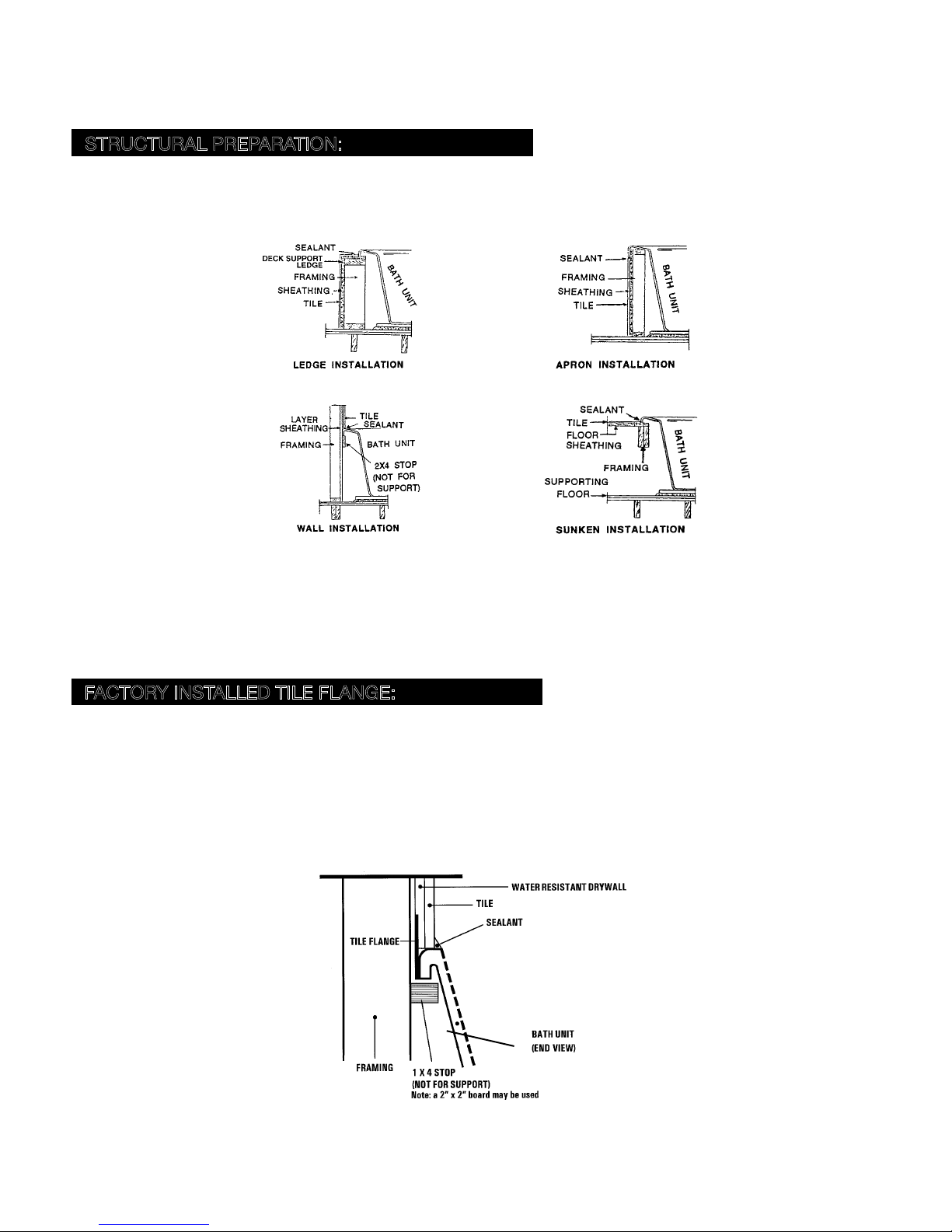
STRUCTURAL PREPARATION:
NOTE: The bath should remain in its shipping carton until time of installation.
1. Literature dimensions are for reference only. Installation dimensions should be taken directly from the tub. An unobstructed access panel of 16” x 16” minimum must be provided at the blower end of the air bath allowing sufficient
clearance to make final connections and for servicing the blower and power panel. Access may be through the wall
or platform apron at the end of the unit. In the case of sunken installations, access should be made through the
ceiling below. A minimum ventilation opening of 2” x 4” for the blower is required and should be designed to draw
in ambient air at a minimum of 72° F.
It is the installer’s responsibility to provide sufficient service access.
Make absolutely certain that access panels and/or service openings are properly placed and that all possible
areas where service may be required are accessible.
2. Install the drain fitting to the bath. THE DRAIN FITTING WILL PROTRUDE BELOW THE BASE OF THE TUB
APPROXIMATELY 1 1/2”. Clearance may be needed for the drain by cutting away the subfloor (where possible) or by
blocking below the tub as may be required. WARNING: FACTORY SKIRTS DO NOT ALLOW FOR BLOCKING UP
OF THE TUB BASE. All blocking must be solid and provide uniform support to the tub base.
Note: Watertight installation of the drain and overflow is the installer’s responsibility. Drain and/or overflow leakage
is not included in the warranty of this product.
3. Tub must rest entirely on its base.
recommends preparing a bed of wet mortar in the area where tub is to be installed to assist in leveling and reduce
vibration noise. Carefully level unit, ensuring that uniform support is given to all areas of the base and no portion of
the lip is bearing weight.
4. Frame out under the tub rim as shown in one of the illustrations below. NOTE: Due to the variety of installations
possible, framing procedures other than those described may be required. Level in selected location. Level front to
back and across both sides. A ledge under the rim, or an apron without a ledge, may be constructed as required
(see Diagrams 1A and 1B on page 8). Where installation will be against a wall, stud wall framing should allow for
wall sheathing material to run full length to the floor (see Diagram 1C on page 8). Install tub firmly against sheathing
as indicated, with blocking below rim to prevent deflection or movement of tub. To prevent a rocking movement of
tub after installation, it is important to have rim in contact, but not supported by blocking material.
DO NOT SUPPORT THE BASE OF THE TUB BY THE RIM.
Aquatic strongly
AQUATIC INDUSTRIES, INC. 7
INSTALLATION INSTRUCTIONS
STRUCTURAL PREPARATION:
5. When placing the tub on a platform or cut out (see Diagrams 1A and 1D), the opening should be 1” smaller than the
specified rim dimensions. Extreme care must be taken in this type of installation to ensure the tub will come to rest
entirely on the base.
1A
1C
*Does not apply to freestanding models.
WARNING: ALL ELECTRICAL CONNECTIONS SHOULD BE MADE BY A LOCALLY LICENSED ELECTRICIAN.
6. Another installation option is that of a tile flange. Aquatic offers an optional factory installed tile flange for all rectangular
and corner-unit air baths.
1B
1D
FACTORY INSTALLED TILE FLANGE:
1. Install the air bath unit per the instructions provided in this manual. CAUTION: THE TILE FLANGE DOES NOT
SUPPORT THE TUB! A ledger board must be provided under the bath rim as indicated in the installation instructions.
Take care to ensure tub is not hanging from the ledger boards, as this will void your warranty.
2. Use nails or screws to secure the flange into the studs around the bath.
3. Install water resistant drywall against the tile flange and flush to the top of the air bath deck. Install the tile or other finishing
materials. Apply a second bead of silicone between the first course of tile and the bath deck.
2A
NOTE: Before tub is used, the air bath system should be cleaned in accordance with the procedures on Page 26 of
this manual.
8 AQUATIC INDUSTRIES, INC.

INSTALLATION INSTRUCTIONS
PLUMBING:
1. After securing tub in place, normal waste and overflow, water spout and valves are installed per normal plumbing
procedures, in accordance with all state and local standards.
2. Install standard 1-1/2” trap to drain and overflow. Before proceeding, make final operational check by filling tub with
water to overflow and operate blower for 5 minutes. Carefully check for leaks both while blower is running and after
it has been turned off. Allow water to stand in tub for at least 30 minutes before draining. AQUATIC INDUSTRIES,
INC. WILL NOT BE RESPONSIBLE FOR WATER DAMAGE OF ANY KIND.
3. When selecting fill spout location, check to ensure that spout is long enough to clear the tub rim from its desired
location. If installation is to be on the tub deck, check the back side of tub for adequate space for connection to water
lines and that there are no air channels running under that area of the tub rim before drilling or cutting tub.
4. A service access panel of a minimum of a 16” square must be provided adjacent to blower and control box
assembly.
AQUATIC INDUSTRIES, INC. 9
INSTALLATION INSTRUCTIONS
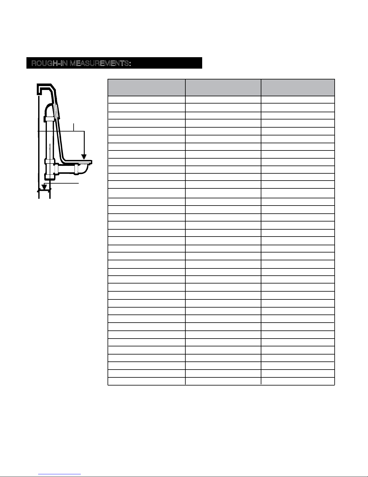
ROUGH-IN MEASUREMENTS:
6A
B
MODEL
From center of overflow
pipe to outside rim
Serenity 1 6 1/4” 13”
Serenity 2 5 3/4” 13 1/4”
Serenity 3 1 1/2” 10 1/2”
Serenity 4 1 1/2” 10 1/4”
Serenity 5 1 3/4” 10”
Serenity 6 5 1/2” 14 1/4”
Serenity 7 2 1/4” 9 3/4”
Serenity Studio 8 2 1/2” 14”
Serenity Studio 9 2 1/2” 13”
Serenity 10 4 3/4” 12 1/8”
Serenity 11 4 3/4” 12 1/8”
A
Serenity Studio 12 4 3/4” 12 1/8”
Serenity 13 3 1/2” 11”
Serenity 14 2 1/2” 15 1/2”
Serenity 15 2 1/2” 9 1/2”
Serenity 16 5 3/8” 12”
Serenity Studio 17 4 3/4” 12 1/8”
Serenity Studio 18 3 1/2” 12 1/2”
Serenity Studio 19 3 1/2” 10 3/4”
Serenity Studio 20 4 3/4” 12 1/8”
Serenity Studio 21 2 1/4” 12 1/4”
Serenity Studio 22 2 1/4” 10 1/2”
Serenity Studio 23 3 1/2” 12 1/2”
Serenity Studio 24 2 3/4” 10 1/2”
Serenity Studio 25 3 1/4” 12”
Serenity Studio 26 2” 10”
Serenity 27 1 3/4” 11 1/4”
Serenity 28 Motif 3 1/2” 12 1/4”
Serenity 29 Motif 5 1/2” 13 1/2”
Serenity 30 Motif 3 1/2” 12 1/2”
Serenity 31 Motif 5 1/2” 13 1/2”
Serenity 32 Motif 6” 14”
Serenity 33 1 1/2” 8 3/4”
Serenity Studio 34 2 3/4” 10 3/4”
Serenity Studio 35 2 3/4” 10 3/4”
Serenity Studio 36 3” 10 1/2”
Serenity 37 3 1/2” 11”
A
From center of drain to tub rim
B
10 AQUATIC INDUSTRIES, INC.
 Loading...