

AquaStar 170 VP User Manual
http://waterheatertimer.org/Troubleshoot-Bosch-Tankless-water-heater.html
INSTALLATION AND OPERATING INSTRUCTIONS
FOR AUTOMATIC INSTANTANEOUS TYPE WATER HEATERS
FOR USE WITH NATURAL AND LIQUEFIED PETROLEUM GAS
MODEL 170 VP
Suitable for water (potable) heating and space heating
WARNING: If the information in this manual is not
followed exactly, a fire or explosion may result
causing property damage, personal injury or death.
FOR YOUR SAFETY
Do not store or use gasoline or other flammable,
combustible or corrosive vapors and liquids in
the vicinty of this or any other appliance.
WHAT TO DO IF YOU SMELL GAS
• Do not try to light any appliance.
• Do not touch any electrical switch; do not use
any phone in your building.
• Immediately call your gas supplier from a
neighbor's phone. Follow the gas supplier's
instructions.
• If you cannot reach your gas supplier, call the
fire department.
-
Installation and service must be performed
by a qualified installer , service agency or
the gas supplier.
Upon completion of the installation, these instructions should be handed to the user of the appliance for
future reference. *REPLACEMENT MANUAL MUST BE PURCHASED
FEATURING: Variable Power - Modulating Gas Valve - Thermostatic Control with Temperature Dial Selector
REF. N° 91606K

TABLE OF CONTENTS
Specifications ..............................................................................Page 3
Rules for Safe Operation.............................................................Page 4-5
General Overview of Aquastar ....................................................Page 6
Locating the Heater for Safe Proper Combustion........................Page 7
Installation ...................................................................................Page 8
Connecting Gas and Water Lines & Pressure Relief Valve .........Page 9-10
Vent Pipe Connection..................................................................Page 10
Safety Before Lighting.................................................................Page 11
Lighting Instructions ....................................................................Page 11
Setting Water Temperature..........................................................Page 12
Maintenance & Service ...............................................................Page 12-14
Trouble Shooting.........................................................................Page 14-18
Cleaning Pilot Assembly..............................................................Page 19
Calibration and Thermostat Test..................................................Page 20-21
Description of Operation and Parts Layout Diagrams .................Page 22-26
Gas Line Size, Vent Size & Height Guide Lines..........................Page 27
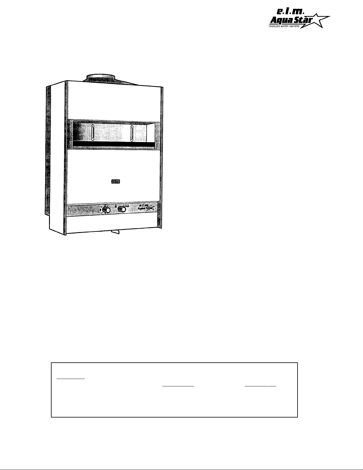
This well engineered, tankless gas water
heater has all the features a water heater
should have:
The instantaneous principle of heating water is
very simple. Cold water enters the heater when
a hot water faucet is opened. This flow of water causes the gas valve to open. Gas flows to
the burners and is ignited by the pilot flame.
The heat exchanger then absorbs the heat generated by the burners and transfers it to the
cold water as it travels through the heat exchanger. When the hot water is turned off, the
gas valve automatically closes and the burners shut off. Your hot water faucet is an ignition key for hot water. You now have complete
control over your hot water energy use. [See
pages 22-26 for detailed Description of Operation and Parts Layout Diagrams].
FEATURES
• Automatic thermostatic control for steady
hot water temperature. Burner output is
proportional to water flow for maximum
energy efficiency.
• Safety thermocouple at pilot and burner.
• Automatic Energy Cut-Off mechanism.
• Built-in gas shut-off valve.
• Stainless steel burners with stabilized blue
flame.
• Built-in corrosion resistant draft inducer.
• Long working life insured by heavy-duty
high quality materials.
• Compact space saver: mounts on wall with
four screws.
• Easy installation.
•41/4 gpm (removable) flow restrictor to
ensure water flow will never exceed heater
capacity .
2
AquaStar 170 VP Specifications:
Gas input........................... max: 165,000 Btu
Water Connection................... 3/4" NPT fitting
H x W x D ...........................35.5"x22.5"x13.5"
Vent.............................................................6"
Gas Connection................................3/4" NPT
Min. Water Pressure............................. 15 Psi
Max. Water Pressure.......................... 150 Psi
Shipping Weight ..................................... 74 lb
Net Weight.............................................. 66 lb
GPM at 90ºF rise......................................2.9*
GPM at 45ºF rise......................................5.8*
Min. Water Flow ........................... 1.1 gal/min
LP GAS Pressure inlet ........... min.: 8"W.C.***
LP GAS Manifold pressure............ 8.66" W.C.
Natural Gas Pressure inlet ... min.:3.5"W.C.***
Natural Gas Manifold Pressure ........ 3.5"W.C.
min: 56,400 Btu
max.: 13"W.C.**
max.:10.5 " W.C.**
* Figured on a 55ºF cold inlet temperature
** Inlet gas pressure must not exceed this value
***For purposes of input adjustment
SETTING THE INLET GAS PRESSURE FOR HIGH ALTITUDES
The pressure regulator provided with the heater is set to deliver the proper gas pressure (as
indicated on the rating plate and in the manual) for altitude up to 2500 feet (758 meters) above
sea level. On appliances being installed above 2500 ft/ 758 m elevation, the inlet gas pressure
should be reset at installation to the value shown below for the altitude of the installation.
NOTE: The gas pressures specified below refer to pressures taken at the test pressure
nipple on the manual gas valve. These readings should be taken while the heater is
operating at full output --i.e. maximum water flow with the temperature setting on #8.
MAXIMUM INLET GAS FLOW PRESSURE SETTING
ALTITUDE NATURAL GAS LIQUID PROPANE
inches W.C. inches W.C.
0 - 2,500 FT / 758 M 6.45" 9.85"
2,000 ft - 4,500ft / 758m - 1212m 5.15" 8.10"
3
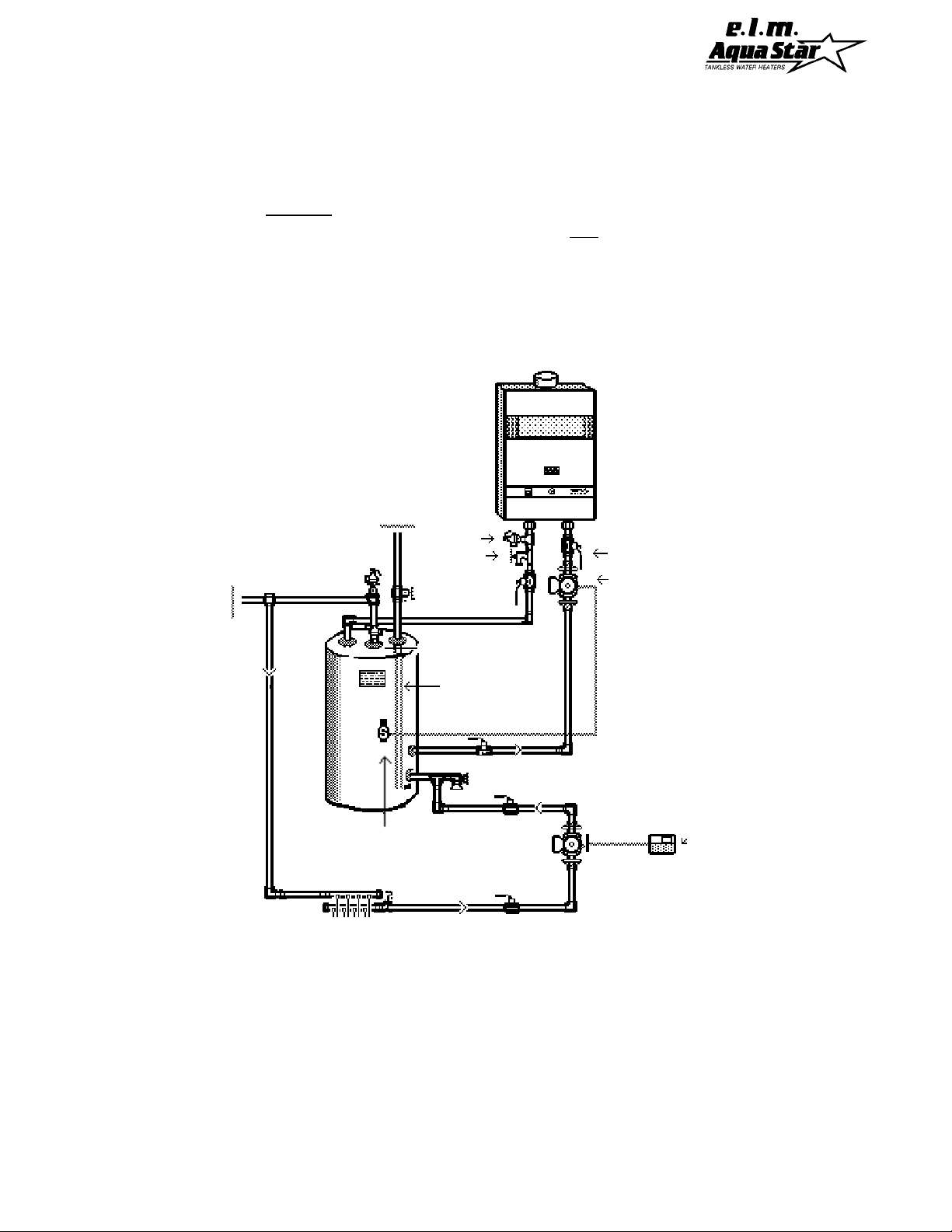
CAUTION: RULES FOR SAFE OPERATION
If you are using the AquaStar for combined space heating and potable water heating (
schematic diagram below),
all piping and other components connected to the system
see
must be suitable for potable water, (b) toxic chemicals such as those commonly used for
boiler treatment to prevent corrosion and freezing must not be introduced into the system,
and (c) if the space heating requires water temperatures higher than those required for
domestic, potable water, a mixing valve or other similar device must be provided to reduce
scald hazard potential. DO NOT CONVERT AN EXISTING, CLOSED HOT WATER HEA TING
SYSTEM TO A COMBINATION SPACE AND POTABLE WATER HEATING SYSTEM USING
THE AQUASTAR OR ANY OTHER HEAT SOURCE.
Cold
Water
Hot
Water
Out
Pressure
In
Relief
Valve
Boiler Drain
Full Port
Ball Valve
Full Port
Ball Valve
Pump (Grundfos
UP26-99BF,
Taco 0011B
or equivalent)
Dip Tube
Secondary
Pump
Aquastat
Sensor
Room
Thermostat
Radiant Floor,
Low Temperature
Fan Coil Units,
Baseboard Heaters,
Snow Melt, or
Root-zone Grid
Fig. 1 Schematic Diagram of Combination Potable Water and Space Heating System
4

RULES FOR SAFE OPERATION
1. You should follow these instructions when
you install your heater.
In the United States: The installation must conform with local codes or, in the absence of local codes, the National Fuel Gas Code ANSI
Z223.1/NFPA 54.
In Canada: The installation should conform
with CGA B149.(1,2) INSTALLATION CODES
and/or local installation codes.
2. Carefully plan where you install the heater.
Correct combustion air supply and flue pipe
installation are very important. If the gas
appliance is not installed correctly, fatal
accidents can result from lack of air, carbon
monoxide poisoning or fire.
3. The place where you install the heater must
have enough ventilation. The National Fire
Codes do not allow water heater installation in
bathrooms, bedrooms or any occupied rooms
normally kept closed. See the section on Pages
7-8 on Locating the Heater.
4. You must vent your heater. See section on
Vent Pipe Connection, Page 10, paragraph 6
and Venting Guide on page 27.
5. The appliance and its individual shutoff valve
must be disconnected from the gas supply piping system during any pressure testing of that
system at pressures in excess of 1/2 psig
(3.5kPa).
6. Keep water heater area clear and free from
combustibles and flammable liquids. Do not
locate the heater over any material which might
burn, such as carpet.
7. Correct gas pressure is critical for the optimum operation of this heater (see specifications
on page 3). Gas piping must be sized to provide the required pressure at the maximum
output of the heater. Check with your local gas
supplier, and see gas line size requirements
on page 27.
8. As a precaution, shut off your heater if you
plan to be away for several days.
9. Should overheating occur and the gas supply
fail to shut off, turn off the manual gas control
valve to the appliance.
10. See instructions on setting the water temperature, page 12.
11. Do not use this appliance if any part has
been under water. Immediately call a qualified
service technician to inspect the appliance and
to replace any part of the control system and
any gas control which has been under water.
The appliance must be isolated from the gas
supply piping system by closing its individual
manual shutoff valve during any pressure testing of the gas supply piping system at test pressures equal to or less than 1/2 psig (3.5kPa).
The appliance and its gas connection must be
leak tested before placing the appliance in operation
5
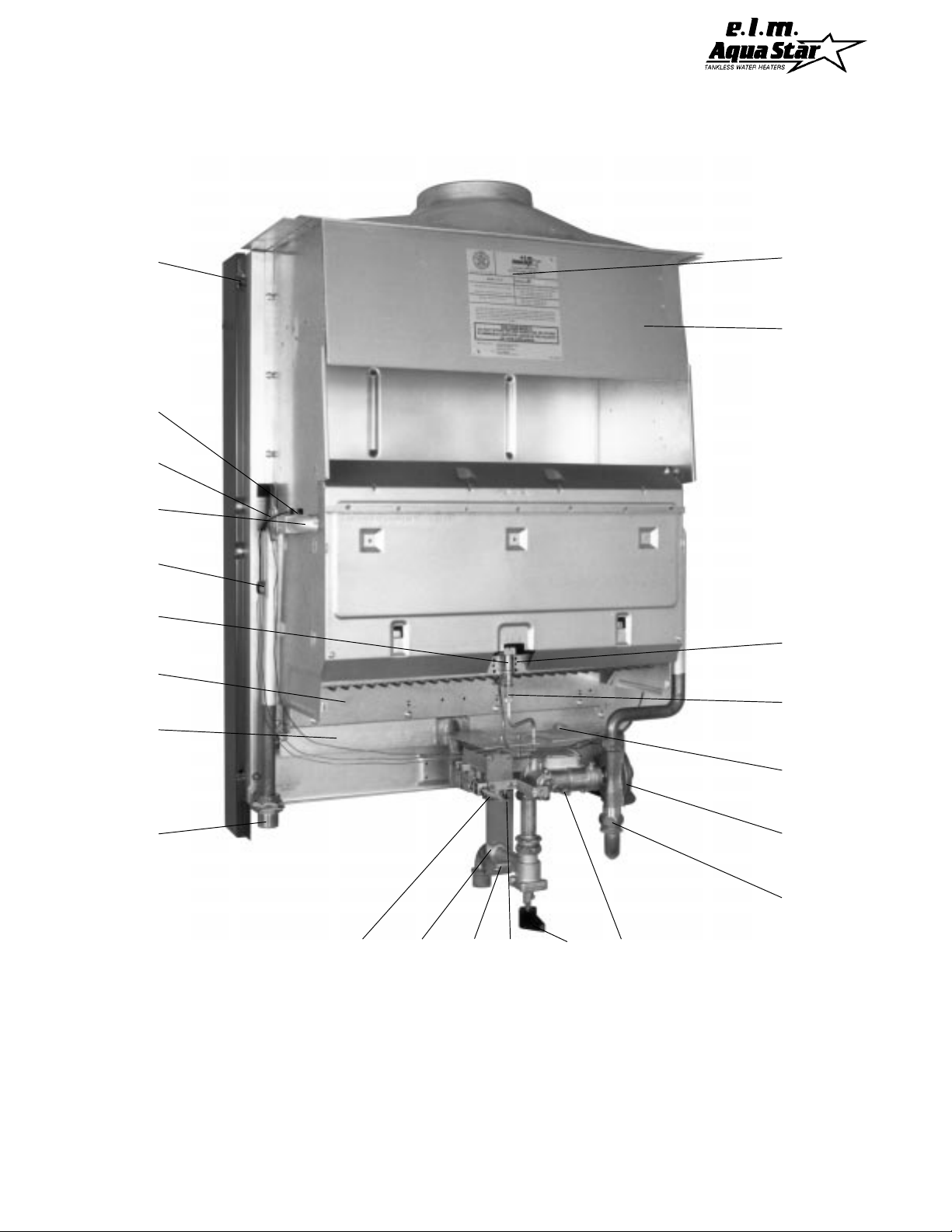
Fig. 2 Parts of AquaStar 170
A
U
C
D
X
W
B
V
T
E
S
F
I
A. Hanging frame and back support
B. Thermostatic sensor
C. Heat exchanger
D. Thermocouple
E. Burners
F. Burner manifold
G. Manifold Gas pressure testing nipple
H. Temperature selector knob
I. Hot water outlet
J. Thermostat adjustment screw
K. Gas Inlet
J
L. Manual gas valve
M. Cold water inlet
P. Pilot starting button
R. Water valve
S. Pilot filter
T. Pilot
U. Overheat sensor 130 °C
V. Domestic Hot Water (DWH) sensor 90 °C
W. Draft hood
X. Rating plate-serial # and gas type etc…
Y. Gas pressure testing nipple
PLYKH
6
G
R
M

LOCATING YOUR HEATER FOR SAFE PROPER COMBUSTION
Carefully select the location of your new heater. For your safety and for proper heater operation,
you must provide an abundant supply of combustion air and install a proper vent. The heater
may still operate even when improperly installed. However, an improper installation will be less
efficient and may damage the heater. Improper installation can even result in human sickness or
death due to oxygen deprivation and carbon monoxide poisoning. Follow the guidelines below:
1. You must not install this appliance in bathrooms, bedrooms, closets or any occupied
rooms normally kept closed.
2. Simultaneous operation of appliances such
as exhaust fans, ventilation systems, clothes
dryers, fireplaces or wood stoves may create a
vacuum effect in your home. This can cause
dangerous combustion by-products to spill back
into your home rather than venting to the outside through the flue.
3. A simple test for proper ventilation is to
inroduce smoke (as from a candle) near the
opening on the front of the heater. Have all
appliances mentioned in the above paragraph
operating at the same time. Have all doors and
windows to the outside shut. If the heater does
not suck the smoke into the opening while the
heater is operating, you need to supply additional combustion air to the heater and/or improve the vent system.
4. Observe the following instructions concerning additional combustion air.
Appliances located in unconfined spaces:
a) An unconfined space is one in which
the volume is greater than 50 cubic feet
per 1000 Btu per hour of the combined
rating of all appliances installed in the
space. That would be 8250 cubic feet
for the AquaStar 170 alone.
b) In unconfined spaces in buildings of
conventional frame, masonry, or metal
construction, infiltration is normally adequate to provide air for combustion,
ventilation, and dilution of flue gasses.
Appliances located in confined spaces:
The confined space shall be provided
with two permanent openings, one commencing within 12 inches of the top and
one commencing within 12 inches of the
bottom of the enclosure. Each opening
shall have a minimum free area of one
square inch per:
-1,000 Btu/hr if all air is taken from inside
the building.
-2,000 Btu/hr if all air is taken from the
outside by horizontal ducts.
-4,000 Btu/hr if all air is taken from the
outside by direct openings or vertical
ducts.
Louvers, grills and screens have a blocking effect. If the effective free area is not
known, assume 20% to 25% for wood louvers and 60% to 75% for metal louvers.
Refer to the National Fuel Gas Code for
complete information. In buildings of tight
construction, all air should be taken from
outside.
5. Place your heater as close to a vent or
chimney as possible. Your hot water lines
should be kept short to save energy . It is always
best to have hot water lines insulated.
6. Having a floor drain or sink nearby is handy
in case you need to drain water from your
heater.
7. Place the heater in a location where water
leaks will do NO DAMAGE to adjacent areas or
lower floors. CONTROLLED ENERGY CORP
IS NOT RESPONSIBLE FOR WATER DAMAGE.
7

8. This heater is not approved for closet installation. For alcove installation, maintain the following minimum clearances from all construction for servicing and proper operations:
Alcove
A. Top 12 inches
B. Front OPEN
C. Back 0 inches
D. Sides 6 inches
(Left side 10" for ease of service)
E. Floor 12 inches*
F. Flue 6 inches (single wall only)
*Do not install over floor covering which is combustible,
such as carpet.
Minimum clearance to combustible materials
should not be less than 6" for single wall flue
pipe. Note that this clearance can be reduced
if combustible materials are protected as per
table VI of the National Fuel Gas Code or if Type
B gas vent is used. (Follow the minimum
clearances for the vent type. We recommend
the use of Type B gas vent).
9. WARNING: THIS WATER HEATER DOES
NOT STORE ANY HOT W ATER. DO NOT INSTALL IN AN AREA WHERE IT COULD
FREEZE. This heater is neither designed for
nor approved for outside installation.
10. The heater must be level before you begin
the piping.
INSTALLATION
Before installing the unit, be certain your heater is
for your type of gas - Propane or Natural Gas.
Identification labels for type of gas are found on the
shipping box, on the right side panel and on the
rating plate which is located in upper part of draft
hood seen by removing front panel (See "X" Fig. 2,
page 6). Also, each gas orifice is stamped with a
number (78 for LPG and 125 for Natural Gas).
1. Hanging the heater on the wall
a) Drill four pilot holes into the wall, making
sure they are level: 2 at the top and 2 at the
bottom.
The holes should be 21 1/4" apart for the wall
mounting screws which are located in the plastic bag on the side panel of the heater. Use a
1/8 inch drill if screws are to go directly into
studs; otherwise size the holes for the plaster
anchors (also located in plastic bag). Tighten
screws to the wall allowing just enough room
between the wall and the screw heads to allow
for the hanging brackets to slip over them.
b) Attach heat shield cross brace to left and
right hanging brackets with 4 screws. Orient
heat shield with the word "
front
" facing you.
Hang bracket assembly on 4 screws on the wall.
c) Remove front panel of heater. To do this,
remove front knobs by pulling them off. Unscrew 3 front panel retaining screws. Pull front
panel up and out. Position the heater over the
hanging bracket metal tabs near the top of the
brackets and then let the heater slip down until
both tabs engage.
2. Connecting the Gas Line
In the United States: The installation must conform with local codes or, in the absence of local codes, the National Fuel Gas Code ANSI
Z223. 1/NFPA 54.
In Canada: The installation should conform with
CGA B149 INSTALLATION CODES and/or local installation codes.
IMPORTANT An appliance gas pressure regulator has been supplied with this unit. This regulator must be installed on the gas line within 6
feet of the heater. National Fuel Gas Code requires that a sediment trap be installed on gas
appliances not so equipped. The 3/4" NPT gas
inlet elbow fitting supplied with the heater connects to the manual gas shutoff valve with a
washer gasket. No pipe dope or thread tape
should be used at this joint. The 3/4" NPT side
of the fitting has a hex shoulder to help you
avoid twisting the elbow and requires pipe dope
or thread tape to make its seal. The 3/4" size
is the minimum for use with Natural Gas and
must not be reduced. Propane gas line size
requirements are less than those for Natural
Gas with some products, but in the case of the
AquaStar 170, the recommended minimum size
is still 3/4", and 7/8" if the length of the tubing
is over 35 feet. See chart, p 27.
8

NOTE: The regulator supplied with the
heater is an appliance level regulator designed for low inlet pressure (less than 1/2
LB or 15"W.C.). DO NOT connect to an unregulated or high pressure propane line.
When your connections are made, check for
gas leaks at all joints (not just ones you made).
Apply some soapy water to all gas fittings and
gas valve. Soap bubbles are a sign of a leak.
NOTE: Do not apply soap solution to pilot filter screen or pilot orifice area. If you have a
leak, shut off the gas. After verifying that required gaskets are in place, tighten appropriate fittings to stop leak. Turn the gas on and
check again with a soapy solution. Never test
for gas leaks using a match or flame.
3. Connecting the water lines
Although water piping throughout your structure may be other than copper, copper piping
should be used for at least three feet before
and after the heater (follow local codes if more
stringent). Keep water inlet pipe to at least 3/4
inch diameter to allow the full flow capacity.
Remember that piping and water pressure must
allow sufficient flow to activate the heater when
drawing hot water from the top floor. If the hot
and cold connections are reversed, the heater
will not function. Be certain there are no loose
particles or dirt in the piping. Blow out or flush
water lines before connecting them to the
AquaStar 170 VP water heater.
4. Connecting the pressure relief valve
A temperature and pressure relief valve must
be installed on the hot water line, close to the
heater. No valve is to be placed between the
relief valve and the heater. Installation shall
be made in such a manner that the discharge
from the temperature and pressure relief valve
will be conducted to a suitable place for disposal when relief occurs. No reducing coupling
or other restriction may be installed in the discharge line. The discharge line must be installed such that it allows complete drainage of
both the valve and the line.
The location of the relief valve must be readily
accessible for servicing or replacement. To accommodate the pressure relief valve, a suitable
fitting connected to an extension of a "T" fitting
can be sweated to the line. Make the T-fitting
extension long enough to ensure that the temperature probe does not interfere with the water flow. The relief pressure of the valve must
not exceed 150 psig. The relief temperature of
the valve must not exceed 210ºF and the discharge capacity must be at least 165,000 Btu
per hour.
5. Vent pipe connection. W ARNING: Do not
reduce the vent pipe size.
This appliance must be vented to the outside
following all local ordinances and specifications
for installing a gas appliance vent or chimney.
The venting system must be constructed so as
to develop a positive flow adequate to remove
flue gasses to the outdoors under all operating
conditions.
The appliance must be located as close as practicable to a chimney or vent. The vent pipe
sections must be fastened with sheet metal
screws. Keep in mind the minimum clearance
from the top of your heater. Remember also
that single wall vent pipe connectors require a
6 inch clearance from combustibles. National
Fuel Gas Code specifies double wall - Type "B"
- vent pipe be used in cold climates and for gas
vents running through attics. We consider
double wall vent pipe preferable in all circumstances. The vent connector should have as
much vertical rise as possible (minimum 12")
before any horizontal run. Any vent section
greater than 45 degrees from vertical is considered horizontal. Horizontal sections of vent
connectors must slope upwards at least 1/4 inch
for every foot of its horizontal length. Keep the
horizontal section short and avoid too many
elbows.
Note: Although the AquaStar has the same venting requirements as other Category I gas appliances, certain features and specific use characteristics make it more important to have a venting
system which exceeds minimum standards.
AquaStar thermostats modulate burner output.
9
 Loading...