

Page 1
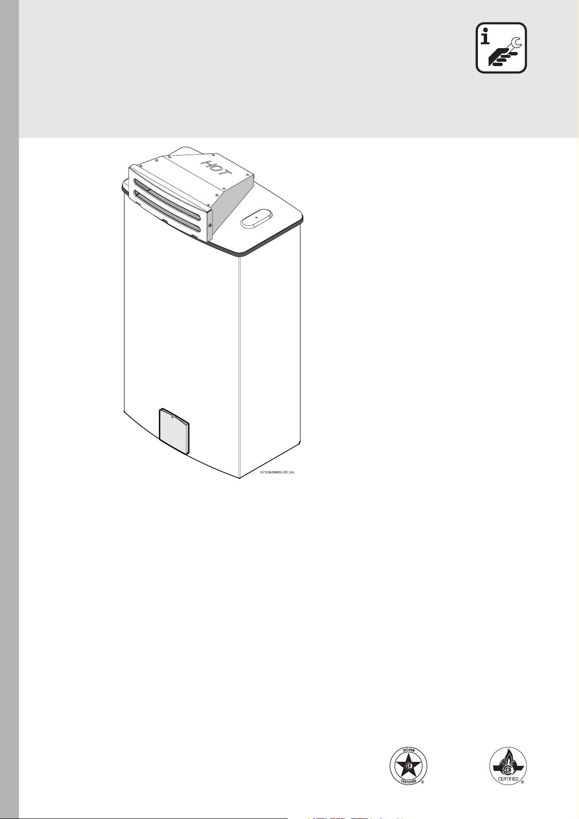
Outdoor Kit Installation Instructions
Aquastar Tankless Water Heater
For Aquastar models: 2400 ES, 2700 ES
Part no. AQOK
Warning: This kit must be installed by a qualified
installer in accordance with these instructions and
all applicable codes and requirements of the
authorities having jurisdiction.
6 720 608 835 US (2007.06) AL
Page 2
Warning
1 Warning
Danger: The top of the outdoor kit will
get very hot during operation. Keep
away from children. Install heater in a
location where the top of the kit cannot
be reached by small children.
Danger: Flue gas will be released
through the outdoor kit. Flue gas is very
hot and contains carbon monoxide. The
outdoor kit cannot be installed indoors.
To prevent risk of fire and carbon
monoxide poisoning, maintain all
clearances indicated in these
instructions.
Danger: Do not place or store any
combustible material within 5 feet of the
appliance. Maintain specified clearance
to combustibles on the wall where the
appliance is installed and any adjacent
walls or overhang. Observe all
clearances required in this manual.
2 Selecting heater location
Before proceeding, read the water heater instructions
manual. If the information in that manual is not followed
exactly, a fire, explosion or poisoning by carbon
monoxide may result causing property damage,
personal injury or death.
B Choose an outside wall for the installation.
Installation on a wall protected by an overhang above
is recommended.
B Size the water and gas connections according to the
instructions in the water heater installation manual.
Use unions when connecting both water lines and
gas supply line to the heater.
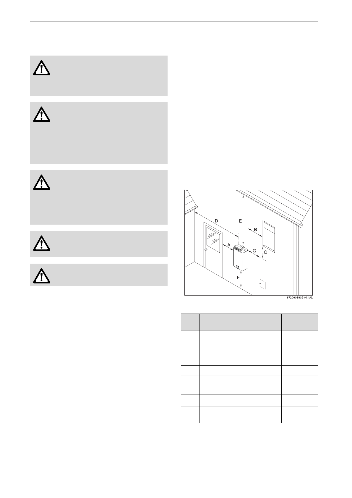
Minimum clearances
If the appliance is installed under an overhang, there
must be a 36” clearance from the top of the appliance
and the mounting area must be open in front and on the
sides of the appliance.
Danger: Surface temperature of the kit
is less than 140°F, except highest top
surface which may reach 300°F.
Warning: Do not mount directly onto
vinyl siding, see Fig. 8.
This outdoor kit includes:
• Supports (2) with screws
• Sealing gasket
• Control panel shield
• Outdoor vent cap.
Fig. 1
Ref. Description
A
B
C
D From any adjacent wall ≥ 4 ft
E
F Above ground ≥ 1 ft
Directly below or adjacent to
an opening; operable
windows, doors and any fresh
air openings
Below a gutter, sanitary
pipework, eaves or overhang
Min.
distances
≥ 4 ft
≥ 3 ft
G
Table 1 Clearances
2
From a gas meter or gas
regulator
≥ 5 ft
6 720 608 835
Page 3
3 Installing outdoor kit
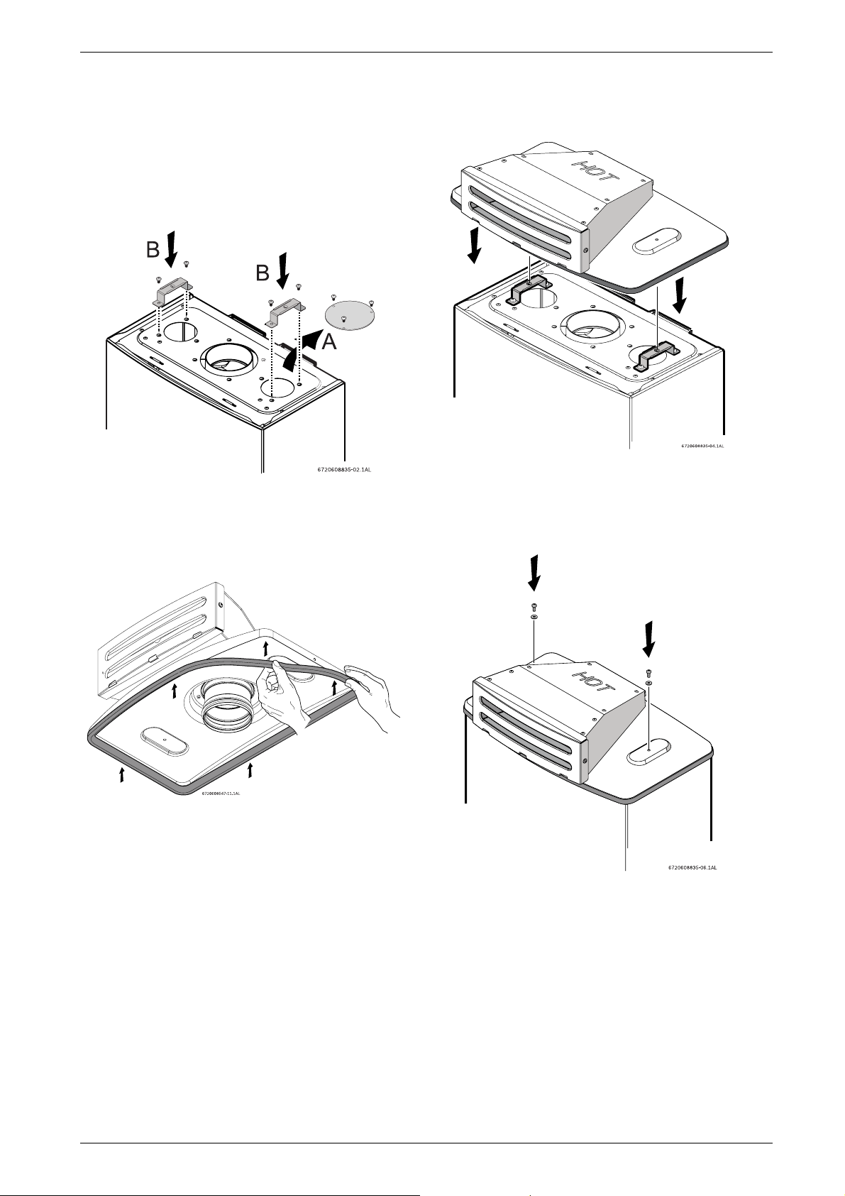
B 1. Remove the cover plate (A) installed on the top of
the appliance, as shown in Fig. 2.
B 2. Fix the supports (B) to the appliance by fastening
the four provided screws, as shown in Fig. 2.
Installing outdoor kit
Fig. 2
Before mounting the outdoor kit in the appliance:
B 3. Attach the gasket provided with the kit as shown
in Fig. 3.
Fig. 3
B Position the outdoor vent cap on the top of the appli-
ance, as shown in Fig. 4.
Fig. 4
B Attach the outdoor vent cap to the appliance by fas-
tening the two provided screws and washers, see
Fig. 5.
6 720 608 835
Fig. 5
3
Page 4
Installing outdoor kit
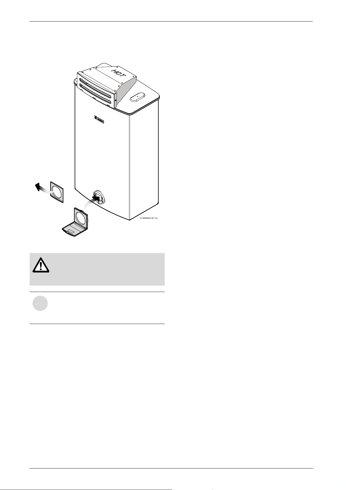
B Replace the control panel shield with shield provided
in kit, see Fig. 6.
Fig. 6
i
Warning: The control panel shield
must always remain closed, except
when making adjustments, to prevent
damage from weather.
NOTE: Once this kit is installed, the
outdoor vent cap will need to be removed
first, before taking the front cover off of the
appliance.
4
6 720 608 835
Page 5
4 Mounting instructions
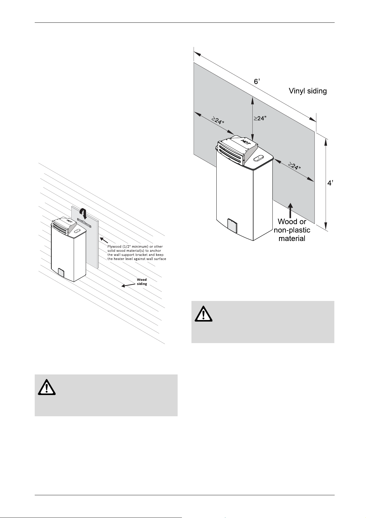
B The water heater is approved for installation directly
on an outside wall. Secure the wall mounting bracket
provided with the water heater to a wall surface. See
Fig. 7.
B The installation method of the mounting bracket will
depend on what type of surface it’s being mounted
on. Due to the varying varieties of building siding or
surfacing, the installer must decide on how best to
support and level the heater on an outside wall. It is
always recommended that horizontal or vertical
support boards or plywood sheathing (1/2”
minimum) first be attached to the wall surface. The
heater must also be kept level on the wall surface.
Mounting instructions
Fig. 7 Installation on wood siding
Warning: Do not mount heater directly
to vinyl siding. With vinyl siding, a 6' x 4'
area of the siding must first be removed
and then replaced with wood or other
non-plastic material. See Fig. 8.
Fig. 8 Installation on vinyl siding
5 Electrical connections
B See Electrical connections section of the water
heater installation manual.
Warning: Confirm that the water
heater is appropriately grounded and
that the installation meets all applicable
electrical codes for outdoor
installations.
B Start and operate the water heater according to the
water heater installation manual. NOTE: Open the
control panel shield to access the controls of the
heater, see Fig. 6.
6 720 608 835
5
Page 6
Measuring carbon dioxide (CO2)
6 Measuring carbon dioxide
(CO
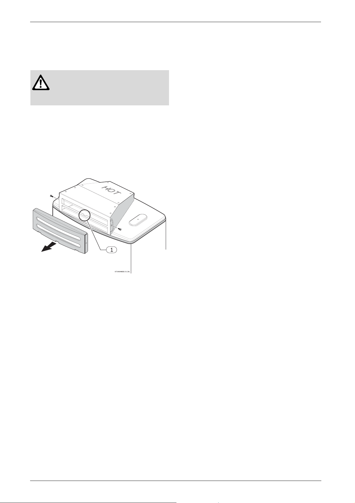
B To measure CO2 on this appliance, a measuring port
is available under the louvered grill on the front of the
outdoor vent cap.
B To access measuring port, remove two screws on
either side of the louvered grill.
B Pull louvered grill free from vent cap.
B When measuring is complete, replace louvered grill
with screws.
)
2
Warning: Outdoor vent cap will get
very hot during operation.
B Ensure the vent cap is cool before
performing the procedure below.
Fig. 9
1 Measuring port
6
6 720 608 835
Page 7

7Notes
Notes
6 720 608 835
7
Page 8

Replacement Parts available from:
BBT North America Corporation
Bosch Group
Bosch Water Heating
50 Wentworth Avenue
Londonderry, NH 03053
BBT Termotecnologia Portugal, S.A.
Estrada de Cacia
3801 - 856 Aveiro - PORTUGAL
Tel. 866-330-2730
www.boschpro.com
Recycled paper © 2007 BBT NORTH AMERICA,
Londonderry, NH
 Loading...