


Operating Instructions For
Water System
INSTR2134 1111
Installer: Please leave manual with homeowner.
Homeowner: Please retain for operation and future maintenance instructions.
SAFETY INFORMATION
Read, understand, and follow all safety information contained in these instructions prior to installation and use of the AP200 Drinking Water System. Retain these instructions for future reference.
Intended use:
The AP200 Drinking Water System is intended for use in filtering potable water in homes and has not been evaluated for other uses. The system is typically installed under a sink, and should be installed by qualified professional installers according to these installation instructions.
EXPLANATION OF SIGNAL WORD CONSEQUENCES
WARNING |
Indicates a potentially hazardous situation, which, if not avoided, could |
result in death or serious injury and/or property damage. |
Indicates a potentially hazardous situation, which, if not avoided, may CAUTION result in property damage.
 WARNING
To reduce the risk associated with choking:
•Do not allow children under 3 years of age to have access to small parts during the installation of this product.
To reduce the risk associated with ingestion of contaminants due to use with water that is microbiologically unsafe or of unknown quality:
•Do not use with water that is microbiologically unsafe or of unknown quality without adequate disinfection before or after the system.
To reduce the risk associated with a hazardous voltage:
•Do not install near electric wiring or piping which may be in the path of a drilling tool when selecting the position to mount the filter bracket.
To reduce the risk of physical injury:
•Shut off inlet water supply and depressurize system as shown in manual prior to cartridge removal.

CAUTION
To reduce the risk associated with property damage due to water leakage:
•Read and follow Use Instructions before installation and use of this system.
•Installation and Use MUST comply with all state and local plumbing codes.
•Protect from freezing. Drain filter when temperatures drop below 40°F (4.4°C).
•Do not install systems in areas where ambient temperatures may go above 110° F (43.3° C).
•Do not install on hot water supply lines. The maximum operating water temperature of this system is 100°F (37.8°C).
•Do not install if water pressure exceeds 125 psi (862 kPa). If your water pressure exceeds psi (552 kPa), you must install a pressure limiting valve. Contact a plumbing professional if you are uncertain how to check your water pressure.
•Do not install where water hammer conditions may occur. If water hammer conditions exist you must install a water hammer arrester. Contact a plumbing professional if you are uncertain how to check for this condition.
•Where a backflow prevention device is installed on a water system, a device for controlling pressure due to thermal expansion must be installed.
•Do not use a torch or other high temperature sources near system, cartridges, plastic fittings or plastic plumbing.
•On plastic fittings, never use pipe sealant or pipe dope. Use PTFE thread tape only, pipe dope properties may deteriorate plastic.
•Take care when using pliers or pipe wrenches to tighten plastic fittings, as damage may occur if over tightening occurs.
•Do not install in direct sunlight or outdoors.
•Do not install near water pipes which will be in path of a drilling tool when selecting the position to mount the bracket.
•Mount system in such a position as to prevent it from being struck by other items used in the area of installation.
•Ensure that the location and fasteners will support the weight of the system when installed and full of water.
•Ensure all tubing and fittings are secure and free of leaks.
•The disposable filter cartridge MUST be replaced every six months, at the rated capacity or sooner if a noticeable reduction in flow rate occurs.
IMPORTANT NOTES
•Failure to follow instructions will void warranty.
•Allow a minimum of 7 1/2” (19.5 cm) clear space under filter to facilitate cartridge change.
•Install with the inlet and outlet ports as labeled. Make sure not to reverse connections.
•Do not crimp copper tubing.
GETTING STARTED
Your new Aqua-Pure® AP200 Drinking Water System will reduce chlorine taste and odor, and sediment from your drinking water. The system installs under the sink on the cold water line. The installation procedure covered in this manual requires the removal of a section of the cold water tube. Soft copper tubing and compression fittings should be purchased locally to complete the installation.
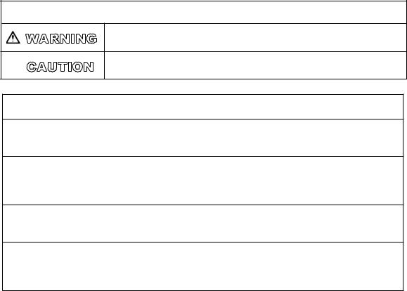
Parts and Materials Included:
1.Mounting Bracket
2.Two Mounting Screws, Four Washers, Two Nuts, And Two Self-tapping Screws
3.System Head
4.Sump
5.AP217 Cartridge
Tools and Parts Required (not included):
•Two 3/8” Pipe Thread Male Connectors
•Compression Fittings
•3/8” Soft Copper Tubing
•Drill (Cordless Recommended)
•Adjustable Wrench
•Phillips Head Screwdriver
•Razor Knife Or Tube Cutter
•PTFE Tape
•Silicone based lubricant
Empty contents of package and identify all parts as shown in diagram. Read all instructions carefully before attempting to start installation. The existing shut-off valve remains in place and still acts as the cold water shut-off.
1 |
2 |
|
3
5
4
IMPORTANT INSTALLATION INSTRUCTIONS
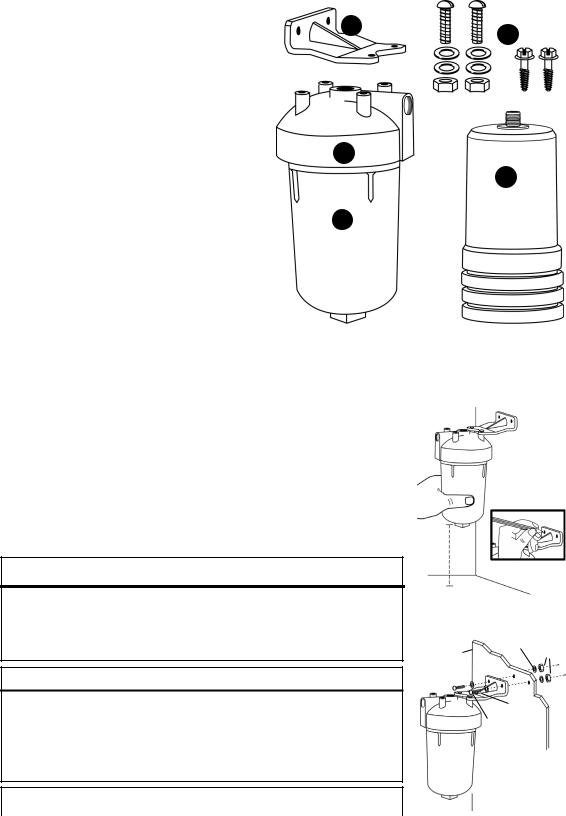
1.Position the filter by holding it against the side of the cabinet wall underneath the sink. Allow at least 7 1/2” beneath the filter to install cartridge. Determine a desirable location for the filter installation and inlet connection. Attach the mounting bracket to appropriate mounting bosses on filter head with the selftapping screws. (Figure 1)
2.Remove drawer from cabinet (if needed) and drill two 7/32” diameter holes through cabinet wall. Fasten filter to wall with nuts and bolts supplied. Use washers on both sides of the wall. Mounting to the cabinet side wall gives the filter good, rigid support. (Figure 2)
 WARNING
To reduce the risk associated with a hazardous voltage due to an installer drilling through existing electric wiring or water pipes in the area of installation:
•Do not install near electric wiring or piping which may be in the path of a drilling tool when selecting the position to mount the filter bracket.
CAUTION
To reduce the risk of property damage due to water leakage:
•Install on COLD water lines only.
•Mount filter in such a position as to prevent it from being struck by other items.
•Do not install near water pipes which will be in path of a drilling tool when selecting the position to mount the bracket.
IMPORTANT NOTES
7 1/2”
|
Figure 1 |
Cabinet |
Washers |
Side Wall |
Nuts |
|
Washers |
|
Screws |
• Allow a minimum of 7 1/2” (19.5 cm) clear space under filter to facilitate |
Figure 2 |
|
cartridge change. |
||
|
||
|
|

IMPORTANT INSTALLATION INSTRUCTIONS (Continued)
3.Wrap a 3” (7.62 cm) long piece of PTFE tape to the right around the male threads of the fittings. Wrap tightly so that it conforms to the threads of the fitting and overlaps about 1/2”. (Figure 3)
4.Screw one fitting into the filter outlet (top) and the other fitting into the filter inlet
(side). Tighten both fittings with a wrench.
Do not overtighten. (Figure 4)
Figure 3
Compression
Fittings
8. Cut two lengths of 3/8” soft copper tubing and bend to shape as shown.
Bend tubing to form gentle curves rather
than sharp bends. Tubing (Figure 8)
IMPORTANT NOTE
Do not crimp copper tubing.
9.Connect both pieces of tubing to filter and water tube as shown with compression fittings. Do not overtighten nuts.
(Figure 9)
Figure 8
Outlet
Completed Connections
Inlet
Figure 9
5.Measure down from the centerline of the filter inlet about 3” and marke the tube.
From this mark, measure up 8” and mark the tube. This is the section of the tube to be removed. If necessary, because of tight quarters, additional tube can be cut away. (Figure 5)
6.Cut the cold water tube. Place a pan under tube to catch any water that may be present. (Figure 6)
CAUTION
•Install on COLD water lines only.
7.Two compression fittings are required for the tube ends. Check the tube size. Use 5/8” x 3/8”, 3/8” x 3/8” or 1/2” x 3/8” compression fittings as required. Slip nut and ferrule on water tubing as shown and fasten fittings in place.
(Figure 7)
Figure 4
Cold Water Line
Shut Off
Valve
Figure 5
Cold Water Line
Section of Tubing
Removed
Figure 6
Nut
Ferrule
Compression Fittings
Ferrule
Nut
Figure 7
10.Remove housing by grasping with both hands and turning to the left. A wrench may be used on the
square lug at the bottom of the housing if necessary.
(Figure 10)
11.Install cartridge by threading into head about 5-6 revolutions. Do not overtighten. Lubricate o-ring with a thin film of a silicone based lubricant and put it back in housing groove.
Thread the housing back on the head and hand tighten. Using of wrench to tighten the housing may damage housing and result in water leakage.
(Figure 11)
Figure 10
O-Ring
Cartridge
Figure 11
12.Open the cold water faucet to expel any trapped air. Open the shut-off valve to allow water to enter the filter. If any leaks occur, close the shut-off valve and open the faucet to relieve the pressure, then gently tighten the fitting that is leaking. Flush 10 gallons through system before use (approximately 5 to 7.5 minutes).
 Loading...