


S H A R K
SHARK MULTI-PARAMETER CONTROLLER
& ANALYZER USER’S MANUAL
Rev 3
AquaMetrix Inc. |
Tel: (800) |
742-1413 |
1245 Maple Hill Ct., Unit 7 |
(905) |
954-0841 |
Newmarket, ON |
Fax: (905) |
954-0415 |
Canada, L3Y 9E8 |
www.aquametrix.com |
|

MULTI-PARAMETER CONTROLLER & ANALYZER USER’S MANUAL
S H A R K
Table of Contents
Subject |
Page No. |
|||
Introduction |
|
|
1 |
|
Section 1 - Specifications |
2 |
|
||
Section 2 - Installation |
3 - 5 |
|||
Section 3 - Electrical Connections & Setup |
6 - 14 |
|||
Differential Probe connection & setup |
7 |
|
||
Combination Probe connection & setup |
8 |
|
||
Conductivity Cell (Contacting style) connection & setup |
9 |
|
||
Paddle Wheel Flow Sensor connection & setup |
10 |
|
||
Relay connections |
11 |
|
||
Relay A & B setup |
12 |
|
||
Alarm relay setup |
13 |
|
||
Manual test mode & Relay override |
14 |
|
||
4-20mA Isolated Outputs Channel 1 & Channel 2 |
15 |
|
||
Service & Fuse Replacements |
16 |
|
||
Section 4 - Using the SHARK in pH Mode |
17 |
|
||
LCD Menu |
18 |
- 44 |
||
LED Menu |
45 |
- 46 |
||
Section 5 - Using the SHARK in ORP Mode |
47 |
|
||
LCD Menu |
48 |
- 73 |
||
LED Menu |
74 |
|
||
Section 6 - Using the SHARK in Conductivity Mode |
75 |
|
||
LCD Menu |
76 |
- 102 |
||
LED Menu |
103 |
|||
Section 7 - Using the SHARK in Flow Mode |
104 |
|||
LCD Menu |
105 - 128 |
|||
Appendix A - Probe Configuration Table |
129 |
Return Policy and Warranty Plan |
130 |

MULTI-PARAMETER CONTROLLER & ANALYZER USER’S MANUAL
S H A R K
Introduction
The SHARK multi-parameter controller is a microprocessor based controller capable of measuring one of the following parameters, pH, ORP, conductivity or flow.
When shipped from the factory, the SHARK is not set to measure any one parameter. When the SHARK is powered up for the first time, it will display the meter selection screen where the meter type must be selected. (refer to section 4.6 Meter Selection)
This meter selection screen will only be displayed when the SHARK is powered up for the first time.
After the user selects a meter type the SHARK will remain set to that meter type until it is changed with the meter selection menu function in the Utilities menu.
To return the SHARK to its factory settings, the user must re-select the current meter type from the meter selection menu function. This will override all set-points and return all settings back to the factory settings.
The SHARK User’s menu has been divided into five main categories
-Calibration, used to calibrate the SHARK with the selected sensor
-Utilities, Used to manually control or override the outputs.
-Setup, used to configure the SHARKs many options
-Diagnostics, used to troubleshoot any problems with the SHARK
-Outputs, used to configure the SHARK’s outputs.
There are two displays on the SHARK. A bright LED numeric display with bar graph on the outside front panel, and a 2-line, 16-character LCD display on the inside. The LED readout on the outside panel can be seen several yards away. The distinctive,colorcoded bar graph will immediately indicate if you are within the process parameters that you set (green), if the control relays are on (yellow) and if you are in alarm condition (red). This makes diagnosing pump and alarm malfunctions easy. All configuration and control functions are performed on the LCD menu on the inside front panel.
A universal mounting kit is included for surface,panel and pipe-mount applications. The 1/4 DIN enclosure makes panel-mount cutouts and engineering simple.
SHARK is packaged in a rugged NEMA 4X polycarbonate enclosure making it ideally suited for heavy-duty applications such as industrial wastewater neutralization, municipal water and wastewater, pulp and paper, and process control.
Introduction |
Page 1 |

MULTI-PARAMETER CONTROLLER & ANALYZER USER’S MANUAL
S H A R K
Section I - Specifications
|
|
pH |
ORP |
|
|
Conductivity |
|
|
Flow |
||
Display |
Front Panel: 4 x 7 segment 1/2”LED display, 1 LED indicator 0n-line,7 LED Bar Graph |
|
|
|
|||||||
Inside Panel: 2 x 16 alpha-numeric LCD display |
|
|
|
|
|
|
|
||||
|
|
|
|
|
|
|
|
||||
Power Requirements |
120Vac (±10%) 50/60Hz (less than 12VA) or 240Vac (±10%) 50/60Hz (less than 12VA) |
|
|||||||||
|
|
|
|
|
|
MΩ/cm3 |
0 to 19.99 |
|
0.01 |
|
Flow: 0 to 9999 with selectable |
|
|
|
|
|
|
|
|
flow rate units |
|||
|
|
|
|
|
|
|
0 to 2.000 |
|
0.01 |
|
|
|
|
|
|
|
|
|
|
|
Volume: 0 to 9999 with Auto Range |
||
Measuring Range |
pH: |
0.01 to 14.00 |
ORP: -1999 to +1999mV |
|
|
uS/cm3 |
0 to 20.00 |
|
0.1 |
|
Flow rate units:Gallons (GP),Cubic |
|
|
|
(Dependent on sensor) |
|
|
|
|
|
|
||
|
|
|
|
|
0 to 200.0 |
|
0.1 |
|
|||
|
|
|
|
|
|
|
|
||||
|
Temp: |
0 to 100°C or |
Temp: 0 to 100°C or |
|
|
|
|
|
Feet (CF),Liters (LP),Cubic Meters |
||
|
|
|
|
|
|
|
|
||||
|
|
|
0 to 2000 |
|
1.0 |
|
|||||
|
|
32° to +212°F |
32° to +212°F |
|
|
|
|
|
(CM),custom by entering factor |
||
|
|
|
|
|
|
|
|
|
|||
|
|
|
|
|
|
mS/cm3 |
0 to 20.00 |
|
10 |
|
related to Gallons |
|
|
|
|
|
|
|
|
|
|
|
|
|
|
|
|
|
|
0 to 200.0 |
|
50 |
|
Time units:Seconds (S), |
|
|
|
|
|
|
|
|
|
|
|||
|
|
|
|
|
|
|
|
|
|
|
|
|
|
|
|
|
|
|
|
|
|
|
|
|
|
|
|
|
Temp: 0 to 100°C or 32° to +212°F |
Minutes (M),Hours (H) |
|||||
|
|
|
|
|
Automatic or Manual |
|
|
|
|||
Temperature |
Automatic or Manual |
Not required |
|
User selectable temperature |
Not required |
||||||
Compensation |
0 to 100°C (32° to +212°F) |
|
compensation slope 0.0 to 10.0%/°C. |
||||||||
|
|
|
|
|
0 to 100°C (32° to +212°F) |
|
|||||
Temperature Unit |
°C or °F |
|
|
|
|
|
|
|
|
|
Not required |
Temperature Sensor |
User selectable: 300Ω NTC Thermistor, 3000Ω NTC Thermistor or Pt. 1000 RTD |
|
|
Not required |
|||||||
Calibration Modes |
Auto-Calibration |
Manual Calibration |
|
|
Dry Calibration |
|
|
|
|||
Manual Calibration |
|
|
Sample Calibration |
|
|
K factor Input |
|||||
Temperature Calibration |
|
|
|
|
|||||||
|
Temperature Calibration |
|
|
Temperature Calibration |
|
||||||
|
|
|
|
|
|||||||
Ambient Conditions |
Temperature: -20°C to +60°C or -4°F to +140°F Humidity: 0 to 90% RH (non-condensing) |
|
|||||||||
Menu Access |
Auto-Calibration, Manual |
Manual-Calibration, |
|
|
Manual Calibration |
|
|
|
|||
Calibration,Temperature |
|
|
|
|
Not available |
||||||
Front Panel |
Temperature Display |
|
|
Temperature Display |
|
|
|||||
Display |
|
|
|
|
|
|
|||||
|
|
|
|
|
|
|
|
|
|
|
|
Menu Access Inside Panel |
Full Access to all parameters of operations menu |
|
|
|
|
|
|
|
|||
Sensor to SHARK |
Differential Sensor: 3000 ft |
|
|
|
300 ft |
|
|
2000 ft |
|||
Distance |
Combination Sensor: 10 ft |
|
|
|
|
|
|||||
|
|
|
|
|
|
|
|
|
|||
|
Two Control Relays, 10A / NO, 5A / NC @ 240VAC or 28VDC. |
|
|
|
|||||||
|
Mode: Process control, Adjustable parameters: process direction,(rising or falling) on-set-point, off set-point, |
||||||||||
Relay Outputs |
(0 to 100% of full scale), cycle timer (on / off, 0 to 600 seconds), failsafe (on / off). |
|
|
|
|||||||
One Alarm Relay, 10A / NO, 5A / NC @ 240VAC or 28VDC. |
|
|
|
|
|
|
|
||||
|
|
|
|
|
|
|
|
||||
|
Mode: High / Low Alarm, Adjustable parameters: Low on / Low off set-point (0 to 100% of full scale, low on must be less than |
||||||||||
|
low off), High On / High Off set-point (0 to 100% of full scale, High on must be greater than High off). |
||||||||||
|
4 to 20mA Channel 1 |
|
|
|
|
|
|
|
|
|
|
Analog Outputs |
Isolated Output, Range expand 0 - 100% of full scale (min segment 10% of full scale), max. load 800Ω |
||||||||||
4 to 20mA Channel 2 |
|
|
|
|
|
|
|
|
|
||
|
Isolated Output, Range expand 0 - 100% of full scale (min segment 10% of full scale), max. load 800Ω |
||||||||||
|
Can be set to track temperature if sensor is equipped with a temperature sensor |
|
|
|
|||||||
Memory Back-up |
All user settings are retained indefinitely in memory (EEPROM) |
|
|
|
|||||||
Mechanical |
Enclosure: NEMA 4X, 1/4 DIN, polycarbonate enclosure with four 1/2”conduit holes |
|
|
|
|||||||
Mounting: Universal Mounting kit for surface, pipe and panel mount, is included |
|
|
|
||||||||
|
|
|
|
||||||||
Sensor Input |
Probe: -600 to +600mV |
Probe: -1999 to +1999mV |
|
|
Cell: 0 to 9999Ω |
|
|
Paddle: 0 to 2000Hz |
|||
Temp. Sensor: 0 to 9999Ω |
Temp. Sensor: 0 to 9999Ω |
|
|
Temp. Sensor: 0 to 9999Ω |
|||||||
|
|
|
|
||||||||
Invalid Entries |
Invalid entries cannot be stored |
|
|
|
|
|
|
|
|||
Manual Test Mode |
Process value can be simulated with arrow keys to verify correct setup of outputs |
|
|
|
|||||||
Manual Relay Override |
Relays can be set to on / off / auto, to verify correct wiring of auxiliary devices, or to manually adjust process |
||||||||||
Output Hold |
All outputs are placed on hold when SHARK is in Menu mode |
|
|
|
|||||||
|
Recall data from last calibration, calibration mode, |
|
|
Recall data from last |
|
|
|
||||
|
|
|
calibration, calibration buffer |
|
|||||||
|
1st & 2nd accepted buffer value and probe mV output, |
|
|
|
|||||||
Calibration Data |
|
|
accepted value, and cell |
Recall store K factor. |
|||||||
calibration temperature, calibration slope, and probe |
|
|
|||||||||
|
|
|
resistance, calibration |
|
|
|
|||||
|
efficiency |
|
|
|
|
|
|
||||
|
|
|
|
temperature |
|
|
|
||||
|
|
|
|
|
|
|
|
|
|||
Auto Return |
User selectable auto return if SHARK is left in menu mode or if relays are left in manual override mode for more than 10 min. |
||||||||||
Display Damping |
User can select rate at which SHARK updates display. Enables display damping of unstable process |
||||||||||
Net Weight |
2.2lbs (1kg) |
|
|
|
|
|
|
|
|
|
|
Approvals |
ULC (pending) |
|
|
|
|
|
|
|
|
|
|
Section I - Specifications |
Page 2 |
MULTI-PARAMETER CONTROLLER & ANALYZER USER’S MANUAL
S H A R K
Section 2 - Installation
2.1 Unpacking
Save the shipping carton and packing material in case the instrument needs to be stored or returned. Inspect the instrument and packing material for shipping damage and report any problems immediately.
2.2 Location
Locate the controller/analyzer close to the sensor. The list below gives typical maximum distances for various sensors. Refer to the sensor specifications for exact information.
• Aquametrix Differential PH Probe |
3000 ft (914 meters) |
• Aquametrix Combination PH Probe |
10 ft (3 meters) |
• Aquametrix Conductivity Probe |
300 ft (91 meters) |
• Aquametrix Flow sensor |
2000 ft (610 meters) |
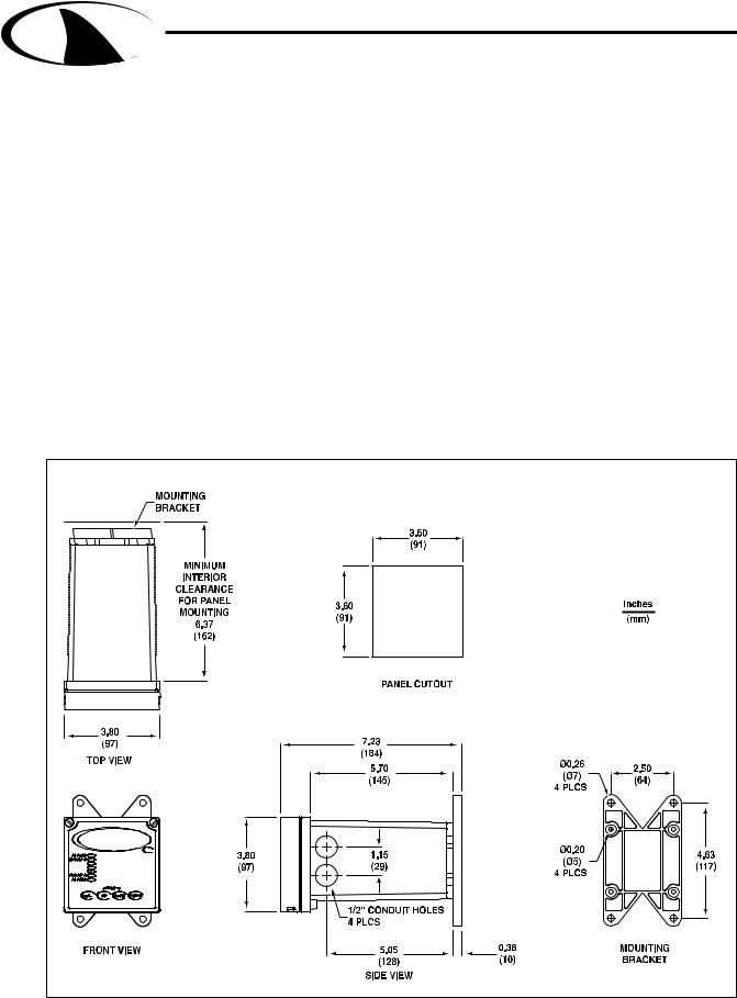
2.3 Mounting
Fig 2.1 Controller dimensions |
Dwg# N106-127 |
Section 2 - Installation |
Page 3 |

MULTI-PARAMETER CONTROLLER & ANALYZER USER’S MANUAL
S H A R K
Section 2 - Installation
Panel Mount – The Shark can be |
Figure 2.2 Panel Mount |
|
panel mounted to a panel using the |
EXTERNAL PANEL |
|
hardware kit provided. The panel |
||
GASKET QTY.1 |
||
cutout dimensions are shown in fig. |
PANEL |
|
(CUSTOMER SUPPLIED) |
||
2.1. |
||
UNIVERSAL MOUNTING |
||
|
BRACKET |
|
|
QTY.1 |
|
|
|
SCREW |
|
|
|
10-24 X 1/2" |
|
|
|
QTY.4 |
|
|
|
SCREW |
|
|
|
1/4-20 X 6" |
|
|
UNIVERSAL |
QTY.4 |
|
|
MOUNTING |
|
|
|
CLAMP QTY.2 |
|
|
|
|
NUT |
|
|
|
1/4-20 |
|
|
|
QTY.4 |
|
|
Dwg# N105-100 |
|
Pipe Mount – The Shark |
Fig. 2.3 |
Vertical Pipe Mount |
|
can also be mounted to a |
|
|
|
horizontal or vertical pipe |
|
|
MIN. PIPE DIA. |
with: |
|
|
1" PIPE (NOMINAL) |
|
|
MAX. PIPE DIA. |
|
|
|
|
2" PIPE (NOMINAL) |
• a minimum outside |
|
|
|
diameter of 1.30” (33mm) |
|
|
|
(for example 1” CPVC |
|
|
UNIVERSAL MOUNTING |
|
|
BRACKET |
|
pipe) |
|
|
QTY.1 |
|
|
|
|
• and a maximum of |
|
|
|
2.375” (60mm) (for |
|
|
|
example 2” CPVC pipe) |
|
|
NUT |
|
|
|
|
|
|
|
10-24 |
|
|
|
QTY.4 |
|
|
|
SCREW |
|
|
|
10-24 X 3-1/2" |
|
|
|
QTY.4 |
|
Dwg# N105-100 |
|
|
Section 2 - Installation |
Page 4 |

MULTI-PARAMETER CONTROLLER & ANALYZER USER’S MANUAL
S H A R K
Section 2 - Installation
Figure 2.4 Horizontal Pipe Mount
MIN. PIPE DIA. 1" PIPE (NOMINAL) MAX. PIPE DIA. 2" PIPE (NOMINAL)
|
|
NUT |
|
|
10-24 |
|
|
QTY.4 |
|
|
SCREW |
|
|
10-24 X 3-1/2" |
|
|
QTY.4 |
|
|
UNIVERSAL MOUNTING |
|
|
BRACKET |
|
|
QTY.1 |
Dwg# N105-100 |
|
|
Surface Mount – The Shark can be |
Figure 2.5 |
Surface Mount |
surface mounted using the hardware |
|
|
kit provided with the unit. |
|
|
|
|
UNIVERSAL MOUNTING |
|
|
BRACKET |
|
|
QTY.1 |
|
|
SCREW |
|
|
10-24 X 1/2" |
|
|
QTY.4 |
|
|
HOLES Ø1/4" |
|
|
FOR MOUNTING SCREWS |
|
|
QTY.4 |
|
|
(CUSTOMER SUPPLIED) |
|
Dwg# N105-100 |
|
Section 2 - Installation |
Page 5 |
MULTI-PARAMETER CONTROLLER & ANALYZER USER’S MANUAL
S H A R K
Section 3 - Electrical Connections and Setup
3.1 Conduit Connections
The Shark has four 1/2” conduit holes, 2 on each side of the enclosure as shown on fig. 2.1. The unit is shipped with these holes plugged with liquid tight conduit seals. These must be left in unused holes to maintain the NEMA 4X integrity. Use approved conduit hubs to connect the conduit, connect these to the conduit before connecting to the enclosure.
Wire Specification: Size and fuse wire accroding to local electrical code. Maximum current not to exceed 10A when used to power auxillary decvices powered via internal connections.
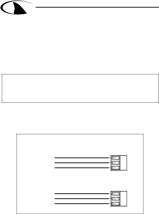
3.2 A.C. Power Connections
Caution: This instrument uses 120 or 240 50/60 Hz AC power. Opening the enclosure door exposes you to potentially hazardous line power voltage which might be present on the terminals of plug P3 and P4. Always remove line power before working in this area. If the relay contacts on P4 are powered from a seperate source from the line power on P3, be sure to disconnect that power before proceeding. The Shark flip out door contains only low voltage and is safe to handle.
The Shark is available in two power models.
The Shark-240 is designed to operate at 240 VAC. The Shark-120 is designed to operate at 120 VAC.
To connect power to the Shark, remove the terminal block plug P3 and connect the wiring as shown below.
Figure 3.1 A.C. Power Connections
AC POWER CONNECTIONS FOR 120 VAC
SHARK-120
NEUTRAL LINE GROUND
G L N
AC POWER CONNECTIONS FOR 240 VAC SHARK-240
LINE
LINE
GROUND
P3
G L L
P3
Dwg# N104-33
Section 3 - Electrical Connections and Setup |
Page 6 |

MULTI-PARAMETER CONTROLLER & ANALYZER USER’S MANUAL
S H A R K
Section 3 - Electrical Connections and Setup
3.3 pH and ORP Differential Probe connections and setup
The drawing shows the connections for the Aquametrix Differential (5 wire) probe. The cable should be run in a conduit separate from AC power wires, and via a separate conduit hole.
Note: Leave 4” to 6” slack for all wires connected to the terminals of P6. Slack required so that wires do not interfere with opening or closing of the front door.
If the cable of the differential probe is cut, the blue
wire is not used.
CAUTION:
Always remove line power before unplugging or plugging in the P6 connector
Figure 3.2 Connections for Differential (5 wire) pH or ORP probe |
|||||||||||||
|
|
GREEN (2) |
|
|
|
|
|
|
|
||||
|
|
|
|
RED (3) |
|
|
|
|
|
|
|
||
|
|
|
|
|
BLACK (4) |
|
|
|
|
|
|||
|
|
|
|
|
|
YELLOW (5) |
|
|
|
|
|||
|
|
|
|
|
|
|
|
|
|
WHITE (10) |
|
||
|
|
|
|
|
|
|
|
|
|
|
SHIELD (8) |
|
|
P6 |
1 |
2 |
3 |
4 |
5 |
6 |
7 |
8 |
9 |
10 |
11 12 |
13 14 15 16 |
17 |
|
|
|
|
|
|
|
|
|
|
|
|
|
DIFFERENTIAL |
Dwg# N104-34 |
|
|
|
|
|
|
|
|
|
|
|
|
pH or ORP PROBE |
|
|
|
|
|
|
|
|
|
|
|
|
|
|
Once connected, step through the LCD menus to select the probe in the order shown. The first two steps may be skipped if the meter is already configured for pH or ORP and a Differential Probe.
When using a pH probe, it is important to ensure that the Shark is reading the probe temperature correctly for accurate temperature compensation. The ORP probe does not require temperature compensation, although the Shark can display process temperature measured by the probe. The factory temperature calibration is usually accurate enough that no adjustments are necessary.
METER SELECTION
PROBE SELECT
MANUAL CAL PH
7.15pH 25.0C
SELECT pH SEC. 4.6 or ORP SEC. 5.5
(IF NECESSARY)
SELECT DIFFERENTIAL PROBE pH SEC. 4.7 or ORP SEC. 5.6 (IF NECESSARY)
MANUAL CALIBRATE pH PROBE SEC. 4.1
or ORP PROBE SEC. 5.1
RUN MODE
Section 3 - Electrical Connections and Setup |
Page 7 |

MULTI-PARAMETER CONTROLLER & ANALYZER USER’S MANUAL
S H A R K
Section 3 - Electrical Connections and Setup
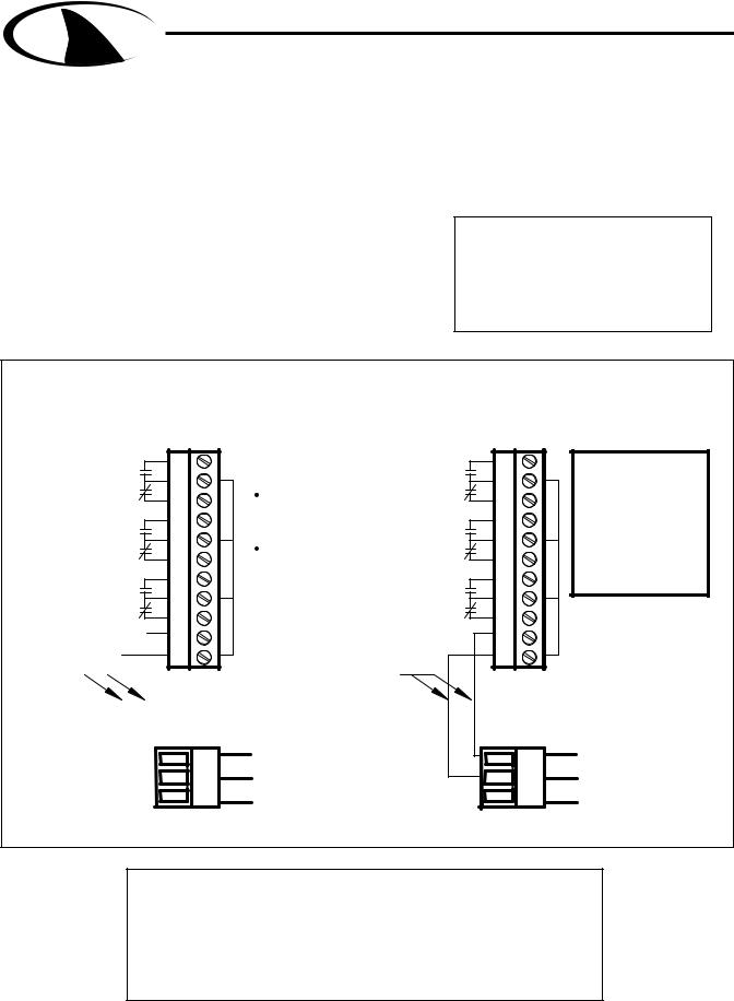
3.4 pH or ORP Combination Probe connections and setup
The drawing shows the connections for the Aquametrix Combination probe. The cable should be run in a conduit separate from AC power wires, and via a separate conduit hole. The cable length should not exceed 10 feet (3 meters).
The 2 wire version has no |
Fig. 3.3 Connections for the 2 and 4 wire Combination Probe |
|
||||||||
|
|
|
|
|
||||||
temperature |
sensor |
and is |
|
|
|
GREEN (4) |
|
|||
connected via a coaxial wire. |
|
|
|
WHITE (5) |
|
|||||
COAX CENTER (3) |
|
|
|
|
||||||
In a pH meter, |
the |
user |
|
|
|
These wires are only |
||||
should |
set |
the |
T |
COMP |
COAX SHIELD (4) |
|
|
JUMPER 2-4 MUST BE |
present with 4-wire |
|
|
|
combination probe. |
||||||||
|
|
|
|
|
|
|
|
|
|
|
OVERRIDE |
menu |
to |
ON |
|
|
|
INSTALLED FOR |
|
||
|
|
|
COMBINATION PROBE |
|
||||||
(Section 4.11) and adjust the |
|
|
|
|
||||||
|
|
|
(CUSTOMER SUPPLIED) |
|
||||||
temperature |
setting |
to |
the |
|
|
|
|
|
||
actual probe temperature. |
|
|
|
|
|
|||||
In an ORP meter, the user |
|
|
|
|
|
|||||
should set the T.DISP OVER- |
|
|
|
|
|
|||||
RIDE to ON (Section 5.10) to |
P6 1 |
2 3 |
4 5 6 7 8 |
9 10 11 12 13 14 15 16 17 |
|
|||||
blank the temperature reading |
|
|
|
|
|
|||||
on the display. |
|
|
|
|
|
|
|
|
||
The 4 wire version has two |
|
|
|
|
|
|||||
additional wires for the probe |
|
|
|
|
|
|||||
internal |
temperature |
sensor. |
|
|
|
|
|
|||
Ensure that the T COMP |
|
|
|
|
|
|||||
OVERRIDE |
or |
T.DISP |
|
|
|
|
|
|||
OVERRIDE is OFF. |
|
|
|
|
|
|
|
|||
Note: Leave 4” to 6” slack for |
|
|
|
|
|
|
|
|
|
|
|
|
|
|
|
|
|
|
|
|
||||||
all wires connected to the ter- |
|
|
|
|
|
|
|
|
|
|
|
|
|
|
|
|
|
|
|
|
||||||
minals of P6. Slack required |
|
|
|
|
|
|
|
|
|
|
|
|
|
|
|
COMBINATION |
||||||||||
|
|
|
|
|
|
|
|
|
|
|
|
|
|
|
||||||||||||
so wires do not interfere with |
|
|
|
|
|
|
|
|
|
|
|
|
|
|
|
pH or ORP PROBE |
||||||||||
|
|
|
|
|
|
|
|
|
|
|
|
|
|
|
||||||||||||
|
|
|
|
|
|
|
|
|
|
|
|
|
|
|
||||||||||||
|
|
|
|
|
|
|
|
|
|
|
|
|
|
|
|
|
|
|
|
|||||||
opening/closing of front door. |
Dwg# N104-35 |
|
|
|
|
|
|
|
|
|
|
|
|
|
||||||||||||
|
|
|
|
|
|
|
Once connected, step throught the LCD menus to select the probe in the order |
|||||||||||||||||||
|
|
CAUTION: |
|
|
|
|||||||||||||||||||||
|
|
|
|
|
shown. The first two steps may be skipped if the meter is already configured for |
|||||||||||||||||||||
|
|
Always remove line |
|
|||||||||||||||||||||||
|
|
|
a Combination Probe. If a two wire pH probe is used, which has no temperature |
|||||||||||||||||||||||
|
|
power before unplugging |
|
|||||||||||||||||||||||
|
|
|
sensor, ensure that the Temp. Comp. Override is set to same temperature as |
|||||||||||||||||||||||
|
|
or plugging in the P6 |
|
|||||||||||||||||||||||
|
|
|
the buffer before calibrating. If a two wire ORP probe is used, you can blank the |
|||||||||||||||||||||||
|
|
connector |
|
|
|
|||||||||||||||||||||
|
|
|
|
|
Temp display with the T DISP OVERRIDE menu. |
|
|
|
|
|
||||||||||||||||
|
|
|
|
|
|
|
|
|
|
|
|
|
|
|
|
|
|
|
|
|
|
|
|
|
|
|
|
|
pH |
|
|
|
|
|
|
|
|
|
|
|
ORP |
|
|
|
|
|
|
|
|
|
|
||
|
|
|
|
|
SELECT PH METER |
|
|
|
|
|
|
|
|
|
|
|
SELECT ORP METER |
|
|
|
|
|
||||
|
METER SELECTION |
|
|
|
|
|
|
|
|
|
METER SELECTION |
|
|
|
|
|
|
|||||||||
|
|
SEC. 4.6 |
|
|
|
|
|
|
|
|
|
SEC. 5.5 |
|
|
|
|
|
|||||||||
|
|
|
|
|
|
|
|
|
|
|
|
|
|
|
|
|
|
|
|
|
||||||
|
|
|
|
|
SELECT COMBINATION PROBE |
|
|
|
|
SELECT COMBINATION PROBE |
||||||||||||||||
|
PROBE SELECT |
|
|
PROBE SELECT |
|
|||||||||||||||||||||
|
|
SEC. 4.7 |
|
|
|
|
|
|
|
|
|
SEC. 5.8 |
|
|
|
|
|
|||||||||
|
|
|
|
|
|
|
|
|
|
|
|
|
|
|
|
|
|
|
|
|
||||||
|
|
|
|
TWO WIRE PROBE WITH NO TEMP SENSOR |
|
|
|
TWO WIRE PROBE WITH NO TEMP SENSOR |
||||||||||||||||||
|
|
|
|
|
|
|
|
|
|
|
|
|
|
|
|
|
|
|||||||||
|
|
|
|
|
MANUAL CALIBRATE |
|
|
|
|
|
|
|
|
|
|
|
MANUAL CALIBRATE |
|
|
|
|
|
||||
|
|
|
|
|
|
|
|
|
|
|
|
|
|
|
|
|
|
|
|
|
||||||
|
MANUAL CAL PH |
|
|
T.COMP OVERRIDE |
|
MANUAL CAL PH |
|
T.DISP OVERRIDE |
|
|||||||||||||||||
|
|
|
|
|
PH PROBE |
|
|
|
|
|
|
|
|
|
|
|
ORP PROBE |
|
|
|
|
|
||||
|
|
|
|
|
SEC. 4.1 |
|
|
MANUAL PROBE |
|
|
|
|
SEC. 5.1 |
DISABLE TEMPERATURE |
||||||||||||
|
|
|
|
|
|
|
TEMPERATURE SETUP |
|
|
|
|
DISPLAY |
||||||||||||||
|
|
|
|
|
|
|
|
|
|
|
|
|
|
|
|
|
||||||||||
|
|
7.15pH 25.0C |
|
RUN MODE |
|
|
SEC 4.10 |
|
7.15pH 25.0C |
|
RUN MODE |
SEC 5.10 |
||||||||||||||
|
|
|
|
|
|
|
|
|
|
|
|
|
|
|
|
|
|
|
|
|
|
|
|
|
|
|
Section 3 - Electrical Connections and Setup |
Page 8 |
MULTI-PARAMETER CONTROLLER & ANALYZER USER’S MANUAL
S H A R K
Section 3 - Electrical Connections and Setup
3.5 Conductivity Cell (Contacting style) connections and setup
The drawing shows the connections for the Aquametrix Conductivity Cells (Contacting style). The cable should be run in a conduit seperate from the AC power wires, and via a seperate conduit hole. The cell cable length should not exceed 300ft. (91 meters).
Note: Leave 4” to 6” slack for all wires connected to the terminals of P6. Slack required so that wires do not interfere with opening or closing of the front door.
CAUTION:
Always remove line power before unplugging or plugging in the P6 connector
Figure 3.4 Connections for Conductivity Cells |
|
|
|||||||||||
|
|
|
|
WHITE (CELL) (1) |
|
|
|
|
|||||
|
|
|
|
|
|
BLACK (CELL) (4) |
|
|
|||||
|
|
|
|
|
|
|
|
|
RED (TEMP. SENSOR) (4) |
|
|||
|
|
|
|
|
|
|
|
|
|
GREEN (TEMP. SENSOR) (5) |
|||
P6 |
1 |
2 |
3 |
4 |
5 |
6 |
7 |
8 |
9 |
10 |
11 12 |
13 14 15 16 |
17 |
|
|
|
|
|
|
|
|
|
|
|
|
|
CONTACTING |
|
|
|
|
|
|
|
|
|
|
|
|
|
CONDUCTIVITY |
Dwg# N104-36 |
|
|
|
|
|
|
|
|
|
|
|
|
CELL |
|
|
|
|
|
|
|
|
|
|
|
|
|
|
Once connnected, step through the LCD menus to select the cell in the order shown. The TEMP COMP CURVE setup default is 1.8%/deg C. This is acceptable for most process applications. If your process is significantly different from this, change the setting in the TEMP COMP CURVE menu.
METER SELECTION
COND RANGE
TEMP SENSOR
TEMP COMP CURVE
OR
SELECT COND METER
SEC. 6.6
SELECT CONDUCTIVITY RANGE SEC. 6.7
ENSURE SENSOR IS CORRECT TYPE
3Kohm NTC (thermistor)
1Kohm RTD
SEC 6.9
SET TEMPERATURE COMPENSATION FOR PROCESS
SEC. 6.13
CALIBRATE WITH
MANUAL CAL COND REFERENCE SOLUTIONS DRY CAL COND
SEC 6.1
1000uS |
25.0C |
RUN MODE |
CALIBRATE WITH FACTORY SPECIFIED CELL CONSTANT SEC 6.2
Section 3 - Electrical Connections and Setup |
Page 9 |

MULTI-PARAMETER CONTROLLER & ANALYZER USER’S MANUAL
S H A R K
Section 3 - Electrical Connections and Setup
3.6 Paddle Wheel Flow Sensor connections and setup
The drawing shows the connnections for a typical paddle wheel flow sensor. The cable to the sensor should not exceed 2000’ (600 meters).
The Shark controller also supports the use of an external “flow switch”. When the flow switch input is grounded, either through a dry contact or solid state input, the flow display will be held at zero. This is useful to ensure the flow reading remains locked at zero when conditions require it. The flow will start reading again when the input is opened. If the flow switch function is not desired, simply leave it disconnected and the flow meter will read as normal.
Figure 3.5 Connections for Flow Sensor |
SHIELD |
|
|
|
|
|
|
|
|
+12V (6) |
|
|
|
|||||
|
|
|
|
|
|
|
|
|
|
|
|
|
SIGNAL + (14) |
|
|
|
||
|
|
|
|
|
|
|
|
|
|
|
|
|
SIGNAL - (GND) (15) |
|
||||
|
|
|
|
(FLOW SWITCH INPUT) (13) |
|
|
|
|
|
|
|
|
|
|
|
|
||
|
|
|
|
GND (15) |
|
|
|
9ma |
|
|
|
|
|
|
|
|
|
|
|
|
|
|
|
|
|
|
|
|
|
|
|
|
|
|
|
||
|
|
|
|
|
|
|
|
+12V O.C. |
|
|
|
|
|
|
|
|||
|
|
|
|
|
|
DRY |
|
|
OR |
|
OPEN |
|
|
|
|
|||
P6 1 |
2 3 |
4 5 6 7 8 9 10 11 12 13 14 15 16 |
17 |
|
|
CONTACT |
|
|
|
COLLECTOR |
|
|
|
|||||
CLOSING THE FLOW SWITCH INPUT |
|
|
FLOW SENSOR |
|||||||||||||||
|
|
|
|
TO GROUND WILL ZERO THE FLOW DISPLAY |
EXTERNAL POWERED |
|||||||||||||
|
|
|
|
|
|
|
|
|
|
|
|
|
SHIELD |
SIGNAL + (14) |
||||
|
|
|
|
|
|
|
|
|
|
|
|
|
|
|
|
|||
|
|
|
|
|
|
|
|
|
|
|
|
|
|
|
|
SIGNAL - (15) |
||
|
|
|
|
|
|
|
|
|
|
|
|
|
|
|
|
SHIELD (15) |
||
|
|
|
|
1 |
2 |
3 |
4 |
5 |
6 |
7 |
8 |
9 |
10 |
11 12 |
13 14 15 16 |
17 |
|
|
|
|
|
|
|
|
|
|
|
|
|
|
|
|
|
|
|
|
FLOW SENSOR |
Dwg# N104-37 |
|
|
|
|
|
|
|
|
|
|
|
|
|
|
|
|
|
SELF POWERED |
Note: Leave 4” to 6” slack for all wires connected to the terminals of P6. Slack required so that wires do not interfere with opening or closing of the front door.
CAUTION:
Always remove line power before unplugging or plugging in the P6 connector
Once connected, step through the LCD menus to select the sensor in the order shown. The Sensor K factor (pulses per U.S. Gallon) is usually printed on the side of the sensor or on a label attached to the sensor cable.
METER SELECTION |
SELECT FLOW METER |
|
SEC. 7.4 |
||
|
||
|
ENTER FLOW SENSOR |
|
K FACTOR |
||
CALIBRATION FACTOR |
||
|
||
|
SEC. 7.1 |
|
|
SETUP OF UNITS |
|
UNITS OF VOLUME |
||
OF VOLUME |
||
|
||
|
SEC 7.5 |
|
|
SETUP OF UNITS |
|
UNITS OF TIME |
||
OF TIME |
||
|
||
|
SEC. 7.6 |
|
|
RESET TOTALIZER |
|
TOTALIZER RESET |
||
TO ZERO |
||
|
SEC 7.0 |
TOTAL |
0 |
RUN MODE |
Section 3 - Electrical Connections and Setup |
Page 10 |
MULTI-PARAMETER CONTROLLER & ANALYZER USER’S MANUAL
S H A R K
Section 3 - Electrical Connections and Setup
3.7 Relay connections
The Shark controller has three internal relays. Relays A and B are for control, the Alarm Relay can be configured for alarm functions or as an additional control relay.
The connections to the relays are shown in the drawing. Note that the AC power is internally connected to the relay terminal plug P4. This is used to provide 120V or 240V AC power for the relay contacts.
Wire Specification: Size and fuse wire accroding to local electrical code. Wire size not to exceed 14 AWG.
WARNING
DISCONNECT POWER FROM CONTROLLER AND LOADS WHILE CONNECTING TO THE RELAY OUTPUT TERMINAL PLUG.
Figure 3.6 Connections for Relay A, B and Alarm |
|
RELAY CONNECTIONS FOR 120VAC |
RELAY CONNECTIONS FOR 240vac |
SHARK-120 |
SHARK-240 |
|
N.0 |
RELAY |
||
|
|
|
||
|
N.C. |
A |
||
|
|
|
||
|
N.C. |
RELAY |
||
|
N.O. |
|
|
|
|
|
|
B |
|
|
N.C. |
ALARM |
||
|
N.O. |
|
|
|
Internal |
|
|
|
|
|
|
|
|
|
|
|
|
|
|
|
|
|
||
connections |
|
|
||
|
|
|
|
|
|
|
|
|
|
|
|
|
|
|
|
|
|
|
|
Dwg# N104-38
21 22 23 24 25 26 27 28 29 30 31
P4
N L GNDG
P3
|
W A R N I N G |
N.0 |
A RELAY |
|
PIN 21 must be |
N.C. |
|
|
connected to relays |
|
|
|
for power. |
N.C. |
RELAY |
|
PIN 22 cannot be |
||
|
|
N.O. |
|
|
connected to the |
|
B |
|
|
|
|
|
relays. |
N.C. |
ALARM |
|
|
||
|
|
N.O. |
|
NEUTRAL OUT (22) |
|
|
|
LINE OUT (21)
Internal connections
NEUTRAL
LINE
GROUND
21 22 23 24 25 26 27 28 29 30 31
P4
L L GNDG
P3
W A R N I N G
 PIN 21 must be connected to relays for power.
 PIN 22 cannot be connected to the relays.
LINE OUT (22)
LINE OUT (21)
LINE
LINE
GROUND
Caution:
The contacts are rated at 10 amp N.O. and 5 amp N.C. Do not exceed this rating. When switching larger currents, use an auxillary relay switched by the controller relay to extend the controller relay life. If the relays are controlling an inductive load, use appropriate transient suppression at the load.
Section 3 - Electrical Connections and Setup |
Page 11 |

MULTI-PARAMETER CONTROLLER & ANALYZER USER’S MANUAL
S H A R K
Section 3 - Electrical Connections and Setup
3.8 RELAY A and B Setup
(LCD MENU SECTIONS - pH: 4.18 & 4.19, ORP: 5.17 & 5.18,
Conductivity: 6.18 & 6.19, Flow: 7.15 & 7.16)
Relay A & Relay B on the SHARK are SPDT dry contact relays. They are configurable to operate in response to rising or falling process values. Each relay has independently adjustable on and off setpoints, cycle times, and fail-safe options.
The operator would use the control relays if the device to be controlled is a simple on/off device. For example a pump, solenoid valve, fan, or an indicating light.
The control relays have 6 user configurable settings:
DIRECTION: The relay can be set to control either a rising or falling process. If for example the relay is set to control a falling process, the ON set-point must be set lower than the OFF set-point. If the relay is set to control a falling process the SHARK will not allow the RELAY OFF set point to be set lower than the RELAY ON set-point. This rule will also apply to a rising process.
RELAY ON set-point: This is the process value at which the relay will energize. This value can be set anywhere between 0-100% of the range.
RELAY OFF set-point: This is the process value at which the relay will de-energize. Depending on the direction for which the relay is configured, the RELAY OFF set-point will only be setable in a limited range.
CYCLE ON time: To obtain a tighter process control, and limit over-shoot, the control relay can be set with the cycling feature. This feature, if enabled, will cause the control relay to cycle when the process is between the RELAY ON set-point and RELAY OFF set-point. The cycle on time is the amount of time in seconds that the relay will be energized. It can be set between 0 and 600 seconds.
CYCLE OFF time: The CYCLE OFF time is the amount of time in seconds that the relay will be deenergized, it can be set between 0 and 600 seconds. To disable the cycling feature set the cycle off time to 0.
OVERFEED TIMER: The overfeed timer is designed to help safeguard against a process or instrumentation error causing one of the control relays to remain energized for extended periods of time.
When enabled, the overfeed timer will time out if the control RELAY OFF set point is not reached inside the overfeed time out. The control relays will de-energize, the alarm relay will energize and an LED will flash at the front.
FAILSAFE: The FAILSAFE feature is designed to reverse the normal action of the control relay.
When the relay is set to FAILSAFE OFF the relay will operate as a normal relay. When the relay is de-energized the NO contacts are open and the NC contacts are closed. Thus the device connected via the NO contacts will be off. When the relay becomes energized the device will be on.
When the relay is set to FAILSAFE ON, the normal action of the relay is reversed. Thus the NO contacts act as the NC contact and the NC act as the NO. The device connected to the NC contacts will be energized when the RELAY ON set-point is reached. The relay will be de-energized but because it is acting in reverse the device will be energized. When the RELAY OFF set-point is reached the relay will energize and the device connected to the NC contact will de-energize.
The purpose of the Fail Safe option is to have the device turned on in the event of a power interruption.
The factory default for FAILSAFE is OFF.
Section 3 - Electrical Connections and Setup |
Page 12 |

MULTI-PARAMETER CONTROLLER & ANALYZER USER’S MANUAL
S H A R K
Section 3 - Electrical Connections and Setup
3.9 ALARM RELAY Setup
(LCD MENU SECTIONS - pH: 4.20, ORP: 5.19, Conductivity: 6.20, Flow: 7.17)
The third relay (Relay C) is used as an alarm relay. The alarm relay on the SHARK is a SPDT dry contact relay.
This relay will respond to both a rising and falling process. The alarm relay will act as a low alarm (falling process) and a high alarm (rising process). Both relays will have independently adjustable on and off set-points. The ALARM ON set-points will always be set before the ALARM OFF set-points. The shark will not let the user input a value below the ALARM ON set-point. The same rule holds true for the high alarm.
The control relays have 5 user configurable settings:
ALARM LOW ON set-point: This is the low process value that will cause the relay to energize. This value can be set anywhere between 0-100% of the range.
ALARM LOW OFF set-point: This is the value that the process must reach in order to de-energize the alarm relay after it has dropped below the ALARM LOW ON set-point. This value must be higher than the ALARM LOW ON set-point.
ALARM HIGH ON set-point: This is the process value that will cause the relay to energize. This value can be set anywhere between 0-100% of the range.
ALARM HIGH OFF set-point: This is the value that the process must reach in order to de-energize the alarm relay after it has increased over the ALARM HIGH ON set-point. This value must be lower than the ALARM HIGH ON set-point.
FAILSAFE: This option can be turned on or off. It reverses the normal action of the relay. (see description under control relay)
ALARM SET-POINT ERROR: If the ALARM LOW ON set-point is set higher than the factory default ALARM LOW OFF set-point, when the user advances from the ALARM LOW ON set-point to the ALARM LOW OFF set-point the shark will adjust the ALARM LOW OFF set-point to be equal to the ALARM LOW ON set-point. If the user then tries to decrease the ALARM LOW OFF set-point the Shark will display the ALARM LOW ALARM setup error screen.
This screen will be displayed for 10 seconds, then return back to the setup screen that was previously displayed. If the user presses the down key again the error message will be displayed again for 10 seconds. The user must accept the LOW OFF set-point, equal to, or greater than the LOW ON set-point.
The same conditions apply to the ALARM HIGH set-points. Except the ALARM HIGH OFF setpoint must be lower than the ALARM HIGH ON set-point. If the user tries to increase the ALARM HIGH OFF set-point higher than the ALARM HIGH ON set-point the High Alarm setup error screen will be displayed.
ALARM RELAY DISABLE: If the user sets the ALARM LOW ON set-point and the ALARM LOW OFF set-point equal to 0% of the range. It will disable the low alarm relay.
If the user sets the ALARM HIGH ON set-point and the ALARM HIGH OFF set-point equal to 100% of the range. It will disable the high alarm relay.
Section 3 - Electrical Connections and Setup |
Page 13 |

MULTI-PARAMETER CONTROLLER & ANALYZER USER’S MANUAL
S H A R K
Section 3 - Electrical Connections and Setup
3.10 MANUAL TEST MODE
(LCD MENU SECTIONS - pH: 4.4, ORP: 5.3, Conductivity: 6.4, Flow: 7.2)
Once the relays are configured, the setup can be tested using Manual Test Mode to simulate process changes.
MANUAL TEST MODE is used to simulate a process reading in order to verify the correct response of the outputs. When in the MANUAL TEST MODE, the relays and outputs are no longer placed on hold as they are when in the rest of the menu. The relays and outputs will react to the simulated change in process as if the Shark was in RUN MODE.
Note that when the user exits the MANUAL TEST
MODE, the relays and outputs will remain in the
MANUAL TEST MODE state until the user enters
RUN MODE.
3.11 RELAY OVERRIDE
(LCD MENU SECTION - pH: 4.5, ORP: 5.4, Conductivity: 6.5, Flow: 7.3)
Relay Override is used to manually override the state of the relays. The user is able to set the operating mode of the relay as AUTO/ON/OFF (the default and RUN MODE states are AUTO).
This feature can be used to energize or de-energize the relays to manually correct the process, or to shut down an ancillary device to perform maintenance. When in the RELAY OVERRIDE mode, the relays are no longer placed on hold as they are when in the other menus.
Note that if the RELAY AUTO RETURN is set to "ON", the controller will place all the relay settings back to AUTO 10 minutes after the Shark returns to the run mode..
Section 3 - Electrical Connections and Setup |
Page 14 |

MULTI-PARAMETER CONTROLLER & ANALYZER USER’S MANUAL
S H A R K
Section 3 - Electrical Connections and Setup
3.12 4-20 mA Isolated Outputs
Channel 1 and Channel 2
(LCD MENU SECTIONS - pH: 4.21 & 4.22, ORP: 5.20 & 5.21,
Conductivity: 6.21 & 6.22, Flow: 7.18 & 7.19)
The Shark Controller has two 4 to 20mA outputs, electrically isolated from each other and ground. Either output can source current into a maximum of 800 ohms.
Channel 1 (the primary output) is located on the flip out door, terminal plug P6. Channel 1 is dedicated to track the process and has fully independent and fully adjustable 4 & 20 mA output setpoints. This will enable the operator to span the output over the desired range.
Channel 2 (the secondary output) is located in the enclosure terminal plug P1. Channel 2 can be selected to track the process value or temperature and has fully independent and adjustable 4 & 20 mA output setpoints.
Both Channel 1 and 2 can be precisely trimmed through the LCD menu for precision applications.
The drawing shows the connections for both outputs.
Wire Specification: 22 AWG 7/30, insulation 0.010”
Figure 3.7 Connections for the 4-20mA outputs
|
|
|
|
|
|
|
|
|
|
|
|
51 |
|
|
|
30 31 |
|
|
|
|
|
|
|
5453 52 |
|
||
|
|
|
28 29 |
|
|
|
|
|
|
|
5756 55 |
|
|
|
|
|
25 26 27 |
|
|
|
|
|
|
|
61 60 59 58 |
Secondary Output |
|
|
|
|
24 |
|
|
|
|
|
|
|
63 62 |
CH2 4-20mA + |
|
|
|
|
23 |
|
|
|
|
|
|
|
64 |
CH2 4-20mA - |
|
|
|
|
21 22 |
|
|
|
|
|
|
|
67 66 65 |
||
|
|
|
|
|
|
|
|
|
|
|
|||
|
|
|
|
P4 |
|
|
|
P3 |
|
P1 |
|
||
|
|
|
|
|
|
|
|
|
|
|
|
|
Primary Output |
|
|
|
|
|
|
|
|
|
|
|
|
|
CH1 4-20mA + |
|
|
|
|
|
|
|
|
|
|
|
|
|
CH1 4-20mA - |
P6 |
1 |
2 |
3 |
4 |
5 |
6 |
7 |
8 |
9 |
10 |
11 12 |
13 14 15 16 |
17 |
Dwg# N104-39 |
|
|
|
|
|
|
|
|
|
|
|
|
|
Note: Leave 4” to 6” slack for all wires connected to the terminals of P6. Slack required so that wires do not interfere with opening or closing of the front door.
Section 3 - Electrical Connections and Setup |
Page 15 |

MULTI-PARAMETER CONTROLLER & ANALYZER USER’S MANUAL
S H A R K
Section 3 - Electrical Connections and Setup
3.13 Service
SHARK SERVICE TO BE PERFORMED BY QUALIFIED PERSONNEL ONLY.
3.14 Fuse Replacement
WARNING:
DISCONNECT LINE POWER TO THE UNIT
TO AVOID THE POSSIBILITY
OF ELECTRICAL SHOCK.
1.Proceed after disconnecting line power from the instrument.
2.Open the front panel by rotating the quarter-turn fasteners, using a flat blade screwdriver, to expose the relay board.
3.The fuse, F1, is located in the middle of the relay board, directly above the three terminal connectors.
4.Remove the open fuse and replace it only with a fuse of the same type and rating. REFER TO THE FUSE RATING TABLES BELOW.
5.Close the front panel and secure using the quarter-turn fasteners.
6.Restore power to the unit.
Figure 3.8 Fuse Location
21 22 23 24 25 26 27 28 29 30 31


P4
FUSE
P3
 67 66 65 64 63 62 61 60 59 58 57 56 55 54 53 52 51
P1
P6 |
1 |
2 |
3 |
4 |
5 |
6 |
7 |
8 |
9 |
10 |
11 12 |
13 14 15 16 |
17 |
Dwg# N104-40
Fuse Rating Table for 120 volt operation
Fuse Type: Slo-Blo Fuse Ratings: 250 |
|
fuse 5 x 20mm |
VAC, 100mA |
Fuse Rating Table for 240 volt operation
Fuse Type: Slo-Blo Fuse Ratings: 250 |
|
fuse 5 x 20mm |
VAC, 50mA |
Section 3 - Electrical Connections and Setup |
Page 16 |

MULTI-PARAMETER CONTROLLER & ANALYZER USER’S MANUAL
S H A R K
Section 4 - Using the SHARK in pH Mode
4 DIGIT, 7 SEGMENT LED DISPLAY
1/4" TURN SCREWS |
DISPLAYS PROCESS VALUE IN RUN MODE. |
|
DISPLAYS CALIBRATION DATA IN |
|
CALIBRATION MODE. |
RELAY C (ALARM RELAY) |
|
STATUS LED's (RED) |
|
BOTTOM LED WILL ILLUMINATE |
|
WHEN ALARM RELAY IS |
|
ENERGIZED BECAUSE OF LOW |
|
ALARM CONDITION. |
|
TOP LED WILL ILLUMINATE WHEN |
|
ALARM RELAY IS ENERGIZED |
|
BECAUSE OF HIGH ALARM |
|
CONDITION. |
|
BAR GRAPH LED's (GREEN) |
|
LINEAR INDICATOR OF PROCESS |
|
VALUE. |
|
(REFER TO SECTION 4.13) |
|
CALIBRATION FROM THE
FRONT PANEL
RUN LED (GREEN)
LED WILL BE ILLUMINATED WHEN
SHARK IS IN THE RUN MODE.
WILL BE OFF WHEN SHARK IS IN
THE MENU MODE.
OVERFEED LED (RED)
LED WILL FLASH WHEN THE
OVERFEED TIMER IS ACTIVATED.
 AUXILLARY LED's
NOT USED IN pH MODE.
UNIT LABEL
LABEL TO INDICATE UNIT OF
MEASURE SHARK IS
CONFIGURED FOR.
RELAY B STATUS LED (YELLOW)
LED WILL BE ILLUMINATED WHEN
RELAY B IS ENERGIZED.
RELAY A STATUS LED (YELLOW)
LED WILL BE ILLUMINATED WHEN
RELAY A IS ENERGIZED.
TEMPERATURE DISPLAY
WHEN THE 'UP' AND 'DOWN' ARROW
KEYS ARE PRESSED
SIMULTANEOUSLY, THE LED WILL
DISPLAY THE CURRENT PROCESS
TEMPERATURE FOR 5 SECONDS.
4 PUSH BUTTONS USED TO |
|
|
|
|
FRONT PANEL |
|
THIS FEATURE WILL BE DISABLED IF |
||||||||
CALIBRATE THE SHARK FROM THE |
|
|
|
|
|
THE 'TEMPERATURE COMPENSATION |
|||||||||
FRONT PANEL. |
|
|
|
|
|
|
|
|
|
|
|
|
|
|
OVERRIDE' IS TURNED ON IN THE |
|
|
|
|
|
|
|
|
|
|
|
|
|
|
SETUP MENU. |
|
(REFER TO SECTIONS 4.22 & 4.23) |
|
|
|
|
|
|
|
|
|
|
|
|
|
|
|
|
|
|
|
|
|
|
|
|
|
|
|
|
|
IN THIS CASE THE LED WILL DISPLAY |
|
|
|
|
|
|
|
|
|
|
|
|
|
|
|
|
|
|
|
|
|
|
|
|
|
|
|
|
|
|
|
|
---- IN PLACE OF THE |
|
|
|
|
|
|
|
|
|
|
|
|
|
|
|
TEMPERATURE. |
REMOVABLE TERMINAL BLOCK |
P6 |
|
|
|
|
|
|
|
|
|
|
|
|
|
|
CONNECTORS |
1 |
2 |
3 |
4 |
5 |
6 |
7 |
8 |
9 |
10 |
11 12 |
13 14 15 16 |
17 |
NOTE |
|
"SNAP-ON" CONNECTORS FOR EASY |
|
|
|
|
|
|
|
|
|
|
|
|
|
|
|
WIRING OF YOUR pH SENSOR AND |
|
|
|
|
|
|
|
|
|
|
|
|
|
|
WHEN THE SHARK IS TAKEN INTO |
PRIMARY 4-20mA OUTPUT. |
|
|
|
|
|
|
|
|
|
|
|
|
|
|
MENU MODE VIA THE INSIDE LCD |
(REFER TO SECTIONS 3.3, 3.4 & 3.12) |
|
|
|
|
|
|
|
|
|
|
|
|
|
|
SCREEN, THE FRONT 7-SEGMENT LED |
|
|
|
|
|
|
|
|
|
|
|
|
|
|
|
WILL DISPLAY ----. THE STATUS & |
|
|
|
|
|
|
|
|
|
|
|
|
|
|
|
BAR GRAPH LED's WILL BE TURNED |
|
|
|
|
|
|
|
|
|
|
|
|
|
|
|
OFF. THE 4 PUSH BUTTONS ON THE |
|
|
|
|
|
|
|
|
|
|
|
|
|
|
|
FRONT WILL NOT RESPOND. |
2 LINE, 16 CHARACTER |
|
|
|
|
|
|
|
|
|
|
|
|
|
|
|
LCD DISPLAY |
|
|
|
|
|
|
|
|
|
|
|
|
|
|
|
MAIN MENU INTERFACE |
|
|
|
|
|
|
|
|
|
|
|
|
|
|
|
SCREEN |
|
|
|
|
|
|
|
|
|
|
|
|
|
|
|
|
|
|
|
|
|
|
|
|
|
|
|
|
|
|
SIMPLE THREE-BUTTON INTERFACE |
|
|
|
|
|
|
|
|
|
|
|
|
|
|
|
FOR FAST & EASY SETUP |
|
|
|
|
|
|
|
|
|
|
|
|
|
|
|
(REFER TO SECTIONS 4.0 TO 4.21) |
INSIDE PANEL
Section 4 - Using the SHARK in pH Mode |
Page 17 |

MULTI-PARAMETER CONTROLLER & ANALYZER USER’S MANUAL
S H A R K
pH - Menu Overview 4.0
7.15pH 25.0C |
RUN MODE |
CALIBRATION |
|
UTILITIES
SETUP
DIAGNOSTICS
OUTPUTS
EXIT
FIRMWARE REV
PROBE SELECT
TEMP UNIT
TEMP SENSOR
AUTO RETURN
T.COMP OVERRIDE
DISPLAY DAMPING
BAR GRAPH O/R
EXIT
DISPLAY
FIRMWAVE REVISION SEC. 4.15
MANUAL CAL PH
AUTO CAL PH
TEMP CALIBRATION
EXIT
SELECT TYPE OF |
MANUAL TEST MODE |
|
|
||
pH PROBE |
|
|
SEC. 4.8 |
RELAY OVERRIDE |
|
SELECT DEG C OR DEG F |
||
|
||
SEC 4.9 |
|
|
SELECT TYPE OF |
METER SELECTION |
|
|
||
TEMP SENSOR |
|
|
SEC 4.10 |
RESET OVERFD TMR |
|
ENABLE TIME OUT |
||
|
||
FROM MENU |
|
|
SEC. 4.11 |
EXIT |
|
TEMPERATURE SETUP FOR |
||
|
||
PROBE W/O TEMP. SENSOR |
|
|
SEC 4.12 |
|
SETUP DISPLAY AND
OUTPUT RESPONSE TIME
SEC 4.13
SETUP RESOLUTION
OF FRONT PANEL BAR GRAPH
SEC 4.14
CALIBRATION DATA |
DISPLAY PREVIOUS |
|
CALIBRATION DATA |
||
|
||
|
SEC 4.16 |
|
SENSOR INPUT |
DISPLAY UNCALIBRATED |
|
PROBE DATA |
||
|
||
|
SEC 4.17 |
MANUAL CALIBRATE pH PROBE
SEC. 4.1
AUTO CALIBRATE pH PROBE
SEC. 4.2
CALIBRATE TEMP. SENSOR IN pH PROBE SEC. 4.3
SIMULATE PROCESS VERIFY OUTPUTS SEC. 4.4
MANUALLY OVERRIDE RELAYS
SEC. 4.5
SELECT TYPE OF METER SEC. 4.6
RESETS RELAY OVERFEED TIMER SEC. 4.7
|
EXIT |
|
|
RELAY A |
SETUP |
|
|
RELAY A |
|
|
|
|
|
|
|
|
SEC 4.18 |
|
|
RELAY B |
SETUP |
|
|
RELAY B |
|
|
|
|
|
|
|
|
SEC 4.19 |
|
|
ALARM RELAY |
SETUP |
|
|
ALARM RELAY |
|
|
|
|
|
|
|
|
SEC 4.20 |
|
|
4-20mA CH1 |
SETUP |
|
|
4-20 mA CH 1 OUTPUT |
|
|
|
|
|
|
|
|
SEC 4.21 |
|
|
4-20mA CH2 |
SETUP |
|
|
4-20 mA CH. 2 OUTPUT |
|
|
|
|
|
|
|
|
SEC 4.22 |
NOTE |
|
EXIT |
|
|
|
PRESS THE |
AND |
KEYS |
|
|
TOGETHER TO GO IMMEDIATELY BACK TO |
||
|
|
RUN MODE |
|
pH - Menu Overview 4.0 |
Page 18 |
MULTI-PARAMETER CONTROLLER & ANALYZER USER’S MANUAL
S H A R K
pH - Calibration Menu - Manual Calibrate 4.1
7.15pH 25.0C |
RUN MODE |
|
|
|
|
|
|
|
|
|
|
|
|
|
|
Place the probe in the first buffer solution, be |
|
||||
CALIBRATION |
MANUAL CAL PH |
|
IF BUFFER1 READY |
|
sure to clean and rinse the Probe first with D.I. |
|
||||
|
|
|
PRESS 'DOWN' |
|
water and then insert it in the 7.00 buffer. |
|
|
|||
|
|
|
|
Press |
|
|
|
|
|
|
|
|
|
|
|
|
|
|
|
|
|
|
|
|
RUNNING MANU CAL |
The controller will read the pH value, |
|
|
|
|||
|
|
|
averaging a number of results to get a |
|
|
|||||
|
|
|
BUFFER1 WAIT... |
|
|
|
||||
|
|
|
|
stable calibration value. |
|
|
|
|
||
|
|
|
|
|
Please wait for the controller to complete |
|
|
|||
|
|
|
|
|
the measurement |
|
|
|
|
|
|
|
|
MANUAL CAL PH |
|
When complete, the controller will report |
|
|
|||
|
|
|
BUFFER1 |
7.3 5 > |
the measured value |
|
|
|
|
|
|
|
|
Use the |
and |
keys to adjust |
|
|
|||
|
|
|
UP |
|
|
|
||||
|
|
|
|
the reading until it agrees with the actual |
|
|
||||
|
|
|
|
|
|
|
||||
|
|
|
|
|
buffer pH value |
|
|
|
|
|
|
|
|
MANUAL CAL PH |
|
Then press |
to move the |
|
|
||
|
|
|
BUFFER1 |
7.0 0 > |
cursor to the RH position |
|
|
|
||
|
|
|
MANUAL CAL PH |
|
Then press |
to store the value and move |
|
|||
|
|
|
BUFFER1 |
7.00 > |
|
|||||
|
|
|
to BUFFER2 |
|
|
|
|
|
||
This example shows a MANUAL |
|
|
|
|
Place the probe in the second buffer. |
|
|
|
||
|
|
|
|
Be sure to clean and rinse the Probe first with |
|
|||||
calibration with buffers of 7pH & 4pH. |
|
IF BUFFER2 READY |
|
|
||||||
|
|
D.I. water and then insert it in the 4.00 buffer. |
|
|||||||
|
|
|
|
|
||||||
|
|
|
PRESS 'DOWN' |
|
|
|||||
When performing a manual |
|
|
|
Press |
|
|
|
|
|
|
|
|
|
|
|
|
|
|
|
||
calibration, any two known buffer |
|
|
|
|
|
|
|
|
|
|
solutions can be used. |
|
|
RUNNING MANU CAL |
The controller will read the pH value, |
|
|
|
|||
|
|
|
averaging a number of results to get a |
|
|
|||||
|
|
|
BUFFER2 WAIT... |
|
stable calibration value. |
|
|
|
|
|
|
|
|
|
|
Please wait for the controller to complete |
|
|
|||
|
|
|
|
|
the measurement |
|
|
|
|
|
|
|
|
MANUAL CAL PH |
|
When complete, the controller will report |
|
|
|||
|
|
|
BUFFER2 |
4.4 0 > |
the measured value |
|
|
|
|
|
|
|
|
UP |
|
Use the |
and |
keys to adjust |
|
|
|
|
|
|
|
|
the reading until it agrees with the actual |
|
|
|||
|
|
|
|
|
buffer pH value |
|
|
|
|
|
|
|
|
MANUAL CAL PH |
|
Then press |
to move the |
|
|
||
|
|
|
BUFFER2 |
4.0 0 > |
cursor to the RH position |
|
|
|
||
|
|
|
|
|
|
|
|
|
||
|
|
|
MANUAL CAL PH |
|
Then press |
to store the value and |
|
|
||
|
|
|
BUFFER2 |
4.00 > |
complete the Manual Calibration |
|
|
|
||
|
|
|
|
|
|
|
|
|
||
|
|
|
SLOPE 61.22MV/PH |
|
After 5 seconds, the controller will |
|
|
|
||
|
|
|
|
compute the slope of the calibration, the |
|
|
||||
|
|
|
EFF 95% 24.8C |
|
estimated probe efficiency and the probe |
|
|
|||
|
|
|
|
|
temperature. |
|
|
|
|
|
|
|
|
|
|
If the calibration is OK, use the |
key |
|
|
||
|
|
|
|
|
to move the cursor over the Y text and |
|
|
|||
|
|
|
|
|
press the down key. |
|
|
|
|
|
|
If the calibration did not appear to be |
MANUAL CAL PH |
|
MANUAL CAL PH |
|
|
Press |
to store the calibration |
||
|
correct, press the |
key |
STORE? |
Y N |
STORE? |
Y |
N |
data and return back to the Manual |
||
|
which will return back to the Manual |
Cal menu so the user can select |
||||||||
|
|
|
|
|
|
|
||||
|
Cal menu. |
|
|
|
|
|
|
|
another function. |
|
NOTE
PRESS THE  AND
AND  KEYS
KEYS
TOGETHER TO GO IMMEDIATELY BACK TO
RUN MODE
pH - Calibration Menu - Manual Calibrate 4.1 |
Page 19 |

MULTI-PARAMETER CONTROLLER & ANALYZER USER’S MANUAL
S H A R K
pH - Calibration Menu - Auto Calibrate 4.2
7.15pH 25.0C |
RUN MODE |
|
|
|
|
|
CALIBRATION |
|
MANUAL CAL PH |
|
|
|
|
|
|
AUTO CAL PH |
IF BUFFER1 READY |
|
Place the probe in the first buffer solution, |
|
|
|
|
be sure to clean and rinse the Probe first |
|||
|
|
|
PRESS 'DOWN' |
|
with D.I. water and then insert it in the 7.00 |
|
|
|
|
|
buffer. |
|
|
|
|
|
|
|
|
|
|
|
|
RUNNING AUTO CAL |
|
Press |
|
|
|
|
|
The controller will read the pH value, |
||
|
|
|
BUFFER1 WAIT... |
|
||
|
|
|
|
averaging a number of results to get a |
||
|
|
|
|
|
||
|
|
|
|
|
stable calibration value. |
|
|
|
|
|
|
Please wait for the controller to complete |
|
|
If an errors occurs, the controller will indicate a |
|
|
the measurement |
|
|
|
|
|
|
|
||
|
"BUFFER ERROR" alarm. This could be caused by |
|
|
|
||
|
- using a defective buffer |
|
|
|
|
|
|
- incorrect probe wiring |
|
|
BUFFER ERROR |
|
|
|
- defective probe |
|
|
CONTINUE |
> |
|
|
Press |
to return to the Auto cal menu, try to |
|
|||
|
|
|
|
|||
|
correct the problem and calibrate again, or go to the |
|
|
|
||
|
diagnotics menus to test the probe |
|
|
|
|
|
|
see Section 4.17 |
|
|
|
|
|
|
|
|
AUTO CAL PH |
|
When complete, the controller will report |
|
|
|
|
BUFFER1 |
7.00 > |
the measured value |
|
|
|
|
|
|
||
|
This example shows an AUTO |
|
|
Press the |
key to move to Buffer 2 |
|
|
calibration with buffers of 7pH & 4pH. |
|
|
|
|
|
|
When performing an auto calibration, |
|
|
Place the probe in the second buffer |
||
|
any two standard buffers of 4.00, 7.00 |
|
|
|||
|
|
|
solution.Be sure to clean and rinse the |
|||
|
or 10.00 pH can be used. The buffers |
IF BUFFER2 READY |
|
|||
|
|
Probe first with D.I. water and then insert |
||||
|
will be automatically recognized if the |
PRESS 'DOWN' |
|
it in the 4.00 buffer. |
||
|
probe measures them within +/- 1 pH |
|
||||
|
|
|
Press the |
key |
||
|
of their nominal value. |
|
|
|||
|
|
|
RUNNING AUTO CAL |
|
The controller will read the pH value, |
|
|
|
|
BUFFER2 WAIT... |
|
averaging a number of results to get a |
|
|
|
|
|
stable calibration value. |
||
|
|
|
|
|
||
|
If an errors occurs, the controller will indicate a |
|
|
Please wait for the controller to complete |
||
|
|
|
the measurement |
|
||
|
"BUFFER ERROR" alarm. This could be caused by |
|
|
|||
|
|
|
|
|||
|
- using the same buffer twice |
|
|
|
|
|
|
- using a defective buffer |
|
|
|
|
|
|
- incorrect probe wiring |
|
|
BUFFER ERROR |
|
|
|
- defective probe |
|
|
CONTINUE |
> |
|
|
Press |
to return to the Auto cal menu, try to |
|
|||
|
|
|
|
|||
|
correct the problem and calibrate again, or go to the |
|
|
|
||
|
diagnotics menus to test the probe |
|
|
|
|
|
|
|
|
AUTO CAL PH |
|
When complete, the controller will report the |
|
|
|
|
|
measured value |
|
|
|
|
|
BUFFER2 |
4.00 > |
|
|
|
|
|
|
|
||
If the calibration did not appear to be correct, press the key which will return back to the Auto cal menu.
SLOPE 61.22MV/PH
EFF 95% 24.8C
AUTO CAL PH
STORE? Y N
After 5 seconds, the controller will compute the slope of the calibration, the estimated probe efficiency and the probe temperature.
If the calibration is OK, use the  key to move the cursor over the Y text and press the down key.
AUTO CAL PH |
|
This will store the calibration |
|
STORE? |
Y N |
data and return back to the |
|
Auto cal setup so the user |
|||
|
|
||
|
|
can select another function. |
NOTE
PRESS THE  AND
AND  KEYS TOGETHER TO GO IMMEDIATELY BACK TO RUN MODE
pH - Calibration Menu - Auto Calibrate 4.2 |
Page 20 |

MULTI-PARAMETER CONTROLLER & ANALYZER USER’S MANUAL
S H A R K
pH - Calibration Menu - Temperature Calibration 4.3
7.15pH 25.0C |
RUN MODE |
|
|
|
CALIBRATION |
MANUAL CAL PH |
|
If the Temperature Compensation Override is set to ON |
|
|
|
|
||
|
AUTO CAL PH |
|
(see section 4.12), the Shark cannot calibrate the |
|
|
|
temperature sensor. This display will appear to alert the |
||
|
|
|
user to the condition. |
|
|
TEMP CALIBRATION |
|
TEMP CALIBRATION |
|
|
|
|
TEMP O/R ON |
> DOWN |
|
|
|
The controller displays the current probe |
|
|
|
|
temperature. |
|
|
|
|
If this incorrect, the controller can be |
|
|
|
|
adjusted to compensate. |
|
|
TEMP CALIBRATION |
|
Press the |
key once which will move |
|
22.4C |
> |
||
|
|
|
the cursor over the least sign. digit of the |
|
|
|
|
temperature display. |
|
If the calibration did not appear to be correct, press the key which will return back to the Temp Calibration menu.
TEMP CALIBRATION
22. 4 C >

 Use the
  and
and  to adjust UP the reading until it agrees with the
known temperature of the probe
TEMP CALIBRATION
25. 0 C > 
 Press the
  key once which will move the cursor
back to the RH side of temperature display.
TEMP CALIBRATION |
|
|
Press the |
key to accept the |
|
25.0C |
|
> |
|
||
|
reading and move to the store function |
||||
|
|
|
|||
T FACTOR SHIFTED |
|
|
"T FACTOR SHIFTED" will be |
|
|
|
|
displayed for 5 seconds to indicate that |
|||
|
|
|
|||
|
|
|
the temperature sensor has been |
|
|
|
|
|
calibrated. |
|
|
|
|
|
The Shark will then move to the store |
|
|
|
|
|
function. |
|
|
TEMP CALIBRATION |
|
|
TEMP CALIBRATION |
This will store the calibration data |
|
STORE? |
Y N |
|
STORE? |
Y N |
and return back to the Temp |
|
|
|
|
|
Calibration setup so the user can |
|
|
|
|
|
select another function. |
NOTE
PRESS THE  AND
AND  KEYS TOGETHER TO GO IMMEDIATELY BACK TO RUN MODE
pH - Calibration Menu - Temperature Calibration 4.3 |
Page 21 |

MULTI-PARAMETER CONTROLLER & ANALYZER USER’S MANUAL
S H A R K
pH - Utilities Menu - Manual Test Mode 4.4
|
|
|
Manual Test Mode is used to simulate a process reading |
||
|
|
|
in order to verify the correct response of the outputs. |
||
7.15pH 25.0C |
RUN MODE |
|
When in the Manual Test Mode, the outputs are no |
||
|
|
|
longer placed on hold as they are when in the rest of the |
||
CALIBRATION |
|
|
menu. |
|
|
|
|
|
|
|
|
UTILITIES |
MANUAL TEST MODE |
TEST |
7.00 > |
Press the |
key once which will |
|
|
a b c |
12.0mA |
move the cursor over the least digit of the |
|
|
|
simulated process value. |
|||
|
|
|
|
||
When a relay is energized, the characters a,b,c will change to upper case A,B,C
The CH1 4-20 mA output will track the change in process
TEST |
7.0 0 > |
Use the |
and |
keys to change |
|
the simulated process value. |
|||||
a b c |
12.0mA |
||||
|
|
|
|||
UP |
|
As the value is changed, the state of the relays |
|||
|
|
will change depending on their settings in the |
|||
TEST |
13.1 5 > |
OUTPUTS menu. |
|
||
a/A - state of Relay A |
|
||||
a B c |
19.0mA |
|
|||
b/B - state of Relay B |
|
||||
|
|
|
|||
|
|
c/C - state of Alarm relay |
|||
|
|
As well, Channel 1 4-20 ma output will also |
|||
|
|
follow the process value change. The actual |
|||
|
|
change will depend on how the CH1 output |
|||
|
|
was scaled in the OUTPUTS menus. |
|||
|
|
(See Section 4.21) |
|
||
TEST |
13.1 5 > |
Press the |
|
key once to |
|
a b c 19.0mA |
move the cursor to the RH side |
||||
of the display |
|
||||
|
|
|
|||
TEST |
13.15 > |
Press the |
key to return to the |
||
a b c 19.0mA |
|||||
MANUAL TEST MODE menu |
|||||
|
|
||||
NOTE:
When the user exits the Manual Test Mode, the relays and 4-20mA outputs will remain in the Test Mode state until the operator enters the run mode. The relays and outputs will then revert back to the previous On-line state.
NOTE
PRESS THE  AND
AND  KEYS
KEYS
TOGETHER TO GO IMMEDIATELY BACK TO
RUN MODE
pH - Utilities Menu - Manual Test Mode 4.4 |
Page 22 |

MULTI-PARAMETER CONTROLLER & ANALYZER USER’S MANUAL
S H A R K
pH - Utilities Menu - Relay Override 4.5
7.15pH |
25.0C |
RUN MODE |
|
|
Relay Override is used to manually override the state of the relays, the user |
|
|||||
|
|
|
|
|
is able to set the operating mode of the relay as AUTO/ON/OFF (the default |
|
|||||
|
|
|
|
|
and run mode state are AUTO). |
|
|
|
|||
CALIBRATION |
|
|
|
This feature can be used to turn the relays ON or OFF to manually correct |
|
||||||
|
|
|
the process, or to shut down an ancillary device to perform maintenance. |
|
|||||||
|
|
|
|
|
|
||||||
|
|
|
|
|
When in the Relay Override mode, the outputs are no longer placed on hold |
|
|||||
UTILITIES |
|
MANUAL TEST MODE |
|
|
as they are when in the other menus. |
|
|
|
|||
|
|
|
|
|
|
|
|
|
|
||
|
|
|
|
|
To use the Relay Override |
|
CAUTION: |
|
|||
|
|
|
|
|
Note that if the Relay Auto Return Menu is set to |
|
|||||
|
|
RELAY OVERRIDE |
|
|
function, press the |
key |
|
||||
|
|
|
|
"ON", the controller will place all these settings |
|
||||||
|
|
|
|
|
|
|
|
back to AUTO 10 minutes after the Shark returns to |
|||
|
|
If you wish to Override Relay |
|
|
|
the run mode. |
|
|
|
||
|
|
|
|
|
|
|
|
|
|||
|
|
A, Press the |
key once |
|
|
|
|
|
|
|
|
|
|
which will move the cursor over |
|
|
|
|
|
|
|
||
RELAY OVERRIDE |
to the AUTO/ON/OFF text |
|
|
|
|
|
|
|
|
||
|
Use the |
or |
|
key to |
|
|
|
|
|
||
RELAY A |
AUTO |
> |
|
|
|
|
|
|
|||
change the Override state from |
|
|
|
|
|
||||||
|
|
|
|
|
|
|
|
||||
|
|
|
AUTO - controlled by process |
|
|
|
|
|
|||
|
|
|
settings |
|
|
|
|
|
|
|
|
|
|
|
ON - relay forced on |
|
|
|
|
|
|
||
|
If you do not wish to |
OFFrelay forced off |
If you wish to accept the |
|
|
|
|||||
|
Override Relay A, then |
The relay will react |
Override setting, |
|
|
|
|
|
|||
|
use the |
key to |
immediately. |
|
Press the |
key once |
|
|
|
||
|
move to Relay B |
|
|
|
to move the cursor to the |
|
|
|
|||
|
|
RELAY OVERRIDE |
|
|
RH of the display |
|
RELAY OVERRIDE |
|
Then use the |
key |
|
|
|
|
|
|
|
|
|||||
|
|
RELAY A |
A UTO |
> |
|
|
|
RELAY A AUTO |
> |
to move to the Override |
|
|
|
UP |
|
|
|
|
|
|
|
setting for Relay A |
|
|
|
|
|
|
|
|
|
|
|
|
|
|
|
RELAY OVERRIDE |
|
|
|
|
RELAY OVERRIDE |
|
|
|
|
|
|
RELAY A |
O N |
> |
|
|
|
RELAY A ON |
> |
|
|
|
|
UP |
|
|
|
|
|
|
|
|
|
|
|
RELAY OVERRIDE |
|
|
|
|
RELAY OVERRIDE |
|
|
|
|
|
|
RELAY A |
O FF |
> |
|
|
|
RELAY A OFF |
> |
|
|
|
|
UP |
|
|
|
|
|
|
|
|
|
RELAY OVERRIDE
RELAY B AUTO |
> |
||
If you do not wish to Override Relay B, then use the key to the Alarm Relay
If you wish to Override Relay |
|
|
|
|
|
|||
B, Press the |
key once |
|
|
|
|
|
||
which will move the cursor over |
|
|
NOTE |
|
|
|||
to the AUTO/ON/OFF text |
|
|
|
|
|
|||
|
|
PRESS THE |
AND |
KEYS |
|
|||
|
|
|
|
|
|
|||
|
|
Use the |
or |
key to |
TOGETHER TO GO IMMEDIATELY BACK TO |
|
||
|
|
change the Override state from |
RUN MODE |
|
|
|||
|
|
AUTO - controlled by process |
|
|
|
|
||
|
|
settings |
|
|
|
|
|
|
|
|
ON - relay forced on |
If you wish to accept the |
|
|
|
||
|
|
OFFrelay forced off |
|
|
|
|||
|
|
Override setting, |
|
|
|
|
||
|
|
The relay will react |
|
|
|
|
||
|
|
Press the |
key once |
|
|
|
||
|
|
immediately. |
|
|
|
|||
|
|
to move the cursor to the |
|
|
|
|||
|
|
|
|
|
|
|
||
|
|
|
|
RH of the display |
|
|
|
|
RELAY OVERRIDE |
|
|
RELAY OVERRIDE |
|
Then use the |
key |
||
RELAY B |
A UTO |
> |
|
RELAY B AUTO |
> to move to the Override |
|||
UP |
|
|
|
|
|
|
setting for Relay B |
|
|
|
|
|
|
|
|
|
|
RELAY OVERRIDE |
|
|
RELAY OVERRIDE |
|
|
|
||
RELAY B |
O N |
> |
|
RELAY B ON |
> |
|
|
|
UP |
|
|
|
|
|
|
|
|
RELAY OVERRIDE |
|
|
RELAY OVERRIDE |
|
|
|
||
RELAY B |
O FF |
> |
|
RELAY B OFF |
> |
|
|
|
UP |
|
|
|
|
|
|
|
|
To Alarm Relay (Relay C) Override
pH - Utilities Menu - Relay Override 4.5 |
Page 23 |

MULTI-PARAMETER CONTROLLER & ANALYZER USER’S MANUAL
S H A R K
pH - Utilities Menu - Relay Override 4.5
FROM RELAY B
OVERRIDE MENU
|
|
If you wish to Override Relay |
|
|
|
|
|
|||
|
|
C, Press the |
key |
|
|
NOTE |
|
|
|
|
RELAY OVERRIDE |
once which will move the |
|
|
Relay C is the Alarm Relay |
|
|
||||
|
|
|
|
|
|
|
||||
|
|
|
|
|
|
|
|
|
||
RELAY C |
AUTO |
> |
|
Use the |
or |
key to |
|
|
|
|
|
|
|
|
change the Override state from |
|
|
|
|
||
|
|
|
|
AUTO - controlled by process |
|
|
|
|
||
|
|
|
|
settings |
|
|
|
|
|
|
|
If you do not wish to |
|
ON - relay forced on |
|
|
|
|
|
||
|
|
OFFrelay forced off |
If you wish to accept the |
|
|
|
||||
|
Override Relay C, then |
|
|
|
|
|||||
|
|
The relay will react |
Override setting, |
|
|
|
|
|||
|
use the |
key to |
|
|
|
|
|
|||
|
|
immediately. |
Press the |
key once |
|
|
|
|||
|
the Store function |
|
|
|
|
|||||
|
|
|
|
to move the cursor to the |
|
|
|
|||
|
|
|
|
|
|
|
|
|
||
|
|
RELAY OVERRIDE |
|
RH of the display |
RELAY OVERRIDE |
|
Then use the |
key |
||
|
|
|
|
|
||||||
|
|
RELAY C |
A UTO |
> |
|
RELAY C AUTO |
> |
to move to the Override |
||
|
|
UP |
|
|
|
|
|
|
setting for Relay C |
|
|
|
|
|
|
|
|
|
|
|
|
|
|
RELAY OVERRIDE |
|
|
RELAY OVERRIDE |
|
|
|
||
|
|
RELAY C |
O N |
> |
|
RELAY C ON |
> |
|
|
|
|
|
UP |
|
|
|
|
|
|
|
|
|
|
RELAY OVERRIDE |
|
|
RELAY OVERRIDE |
|
|
|
||
|
|
RELAY C |
O FF |
> |
|
RELAY C OFF |
> |
|
|
|
|
|
UP |
|
|
|
|
|
|
|
|
|
|
If you wish to store the state |
|
|
|
|
|
|
||
|
|
of the Relay Overrides, |
|
|
|
|
|
|
||
|
|
press the |
|
key to |
|
|
|
|
|
|
RELAY OVERRIDE |
highlight the Y character |
|
|
|
|
|
|
|||
|
|
|
|
|
|
|
|
|
||
STORE? |
Y |
N |
|
|
|
|
|
|
|
|
NOT STORED
With "N" highlighted, pressing the  key will NOT store the Override states of the relays, but they will revert to the state they were in before the menu was entered. Note that, if any of the relays were in a specific Override state before the menu was entered (i.e. not in AUTO), they will revert to that state again unless the changes are STORED.
RELAY OVERRIDE
STORE? |
Y |
N |
||
STORED
Then press the  key to store the Override states of all the relays and return back to the Override menu
TO RELAY
OVERRIDE MENU
NOTE
PRESS THE  AND
AND  KEYS
KEYS
TOGETHER TO GO IMMEDIATELY BACK TO
RUN MODE
pH - Utilities Menu - Relay Override 4.5 |
Page 24 |

MULTI-PARAMETER CONTROLLER & ANALYZER USER’S MANUAL
S H A R K
pH - Utilities Menu - Meter Selection 4.6
7.15pH 25.0C
CALIBRATION
UTILITIES
RUN MODE
The Meter Selection menu is used to select the meter type that the controller is configured for, either pH, ORP, Conductivity or FLow. Once selected, the controller will initialize itself for the selected meter's functionality and move to run mode.


 MANUAL TEST MODE
RELAY OVERRIDE |
Press the |
key to initialize the |
|
controller as a pH meter. |
|
METER SELECTION
To reset the controller back to all the factory default values, reselect the current meter type
P H |
PH |
|
ORP |
INITIALIZE? |
Y N |
O RP
CONDUCTIVITY
C ONDUCTIVITY
FLOW
F LOW
EXIT
E XIT
PH
Press the  key to initialize the controller as an ORP meter
ORP
INITIALIZE? Y N
Press the  key to initialize the controller as a Conductivity meter


 CONDUCTIVITY INITIALIZE? Y N
Press the  key to initialize the controller as a Flow meter
FLOW
INITIALIZE? Y N
Press the  key to Exit and return to the Utilities menu
If you do not wish to initialize to this type of meter after all, then press  key to return back to the Meter Selection menu
If you do wish to initialize to this type of meter, press the  key to highlight the Y character
Then press |
PH |
|
|
The controller will initialize itself for a |
INITIALIZE? |
Y N |
|
specific meter |
|||
|
|
NOTE
PRESS THE  AND
AND  KEYS TOGETHER TO GO IMMEDIATELY BACK TO RUN MODE
pH - Utilities Menu - Meter Selection 4.6 |
Page 25 |

MULTI-PARAMETER CONTROLLER & ANALYZER USER’S MANUAL
S H A R K
pH - Utilities Menu - Overfeed Timer Reset 4.7
7.15pH 25.0C |
RUN MODE |
CALIBRATION |
|
UTILITIES |
MANUAL TEST MODE |
|
RELAY OVERRIDE |
|
METER SELECTION |
|
RESET OVERFD TMR |
If the control relay overfeed timer has been enabled, the relay will Òtime outÓ after the specified overfeed time. When the relay times out, it must be manually reset. The time out will be signaled by the time out LED flashing on the front panel.
The reset overfeed timer will reset the timers for both relay A & relay B at the same time.
Press the  key to choose between Y or N.
RESET OVERFD TMR |
RESET OVERFD TMR |
Y N |
Y N |
If you wish to reset the overfeed timer, then press the  key to proceed and return back to the Utilities menu.
If you do not wish to reset the overfeed timer after all, press the  key to highlight the N character and press the
key to return back to the Utilities menu.
NOTE
PRESS THE  AND
AND  KEYS TOGETHER TO GO IMMEDIATELY BACK TO RUN MODE
pH - Utilities Menu - Overfeed Timer Reset 4.7 |
Page 26 |

MULTI-PARAMETER CONTROLLER & ANALYZER USER’S MANUAL
S H A R K
pH - Setup Menu - Probe Select 4.8
7.15pH 25.0C |
RUN MODE |
PROBE SELECT will allow the user to select |
|
|
|
||
CALIBRATION |
|
whether the probe is a 2 or 4 wire |
|
|
combination probe, or a 5 wire differential |
|
|
|
|
probe. |
|
UTILITIES |
|
|
|
SETUP |
PROBE SELECT |
PROBE SELECT |
|
|
|
DIFFERENTIAL |
> |
Press the  key once which will move the cursor over the first character of the probe type.
Note: |
|
|
PROBE SELECT |
Use the |
or |
keys to scroll through |
||
|
|
D IFFERENTIAL |
the probe types available. |
|||||
If using the 2 wire Combination Probe (which |
|
|||||||
|
In this case, the user can select |
|||||||
|
|
|
||||||
doesn't have a temperature sensor), T COMP |
|
UP |
|
|||||
|
|
- the 2 or 4 wire combination probe |
||||||
OVERRIDE must be set to ON, and the actual |
|
|
|
|||||
|
|
|
- the 5 wire differential probe |
|||||
probe temperature set through the T COMP |
|
|
|
|||||
|
|
|
|
|
|
|
||
OVERRIDE menu. |
|
|
|
|
|
Once the correct probe type is selected, |
||
(see sec. 4.12) |
|
|
|
|
|
|||
|
|
|
|
|
|
move to the store function to save the |
||
|
|
|
|
|
|
selection |
|
|
|
|
|
PROBE SELECT |
Press the |
|
key once |
||
|
|
|
C OMBINATION |
|
||||
|
|
|
which will move the cursor |
|||||
|
|
|
|
|
||||
|
|
|
|
|
back to the RH side of the |
|||
|
|
|
|
|
display. |
|
|
|
|
|
|
PROBE SELECT |
|
|
|
|
|
|
|
|
COMBINATION |
> |
|
|
|
|
|
|
|
|
|
Press the |
key to accept the |
||
|
|
|
|
|
setting and move to the store function |
|||
With "N" selected, pressing the |
|
|
Or press the |
key to highlight |
|
|
|
|
|
|
the Y character. |
|
|
|
|
|
|
key will NOT store the selection, but |
|
|
|
|
|
|
|
|
|
|
|
|
|
|
|
|
|
simply return to the PROBE SELECT PROBE SELECT |
|
PROBE SELECT |
|
|
|
|
||
Menu. This function is useful if you |
STORE? |
Y N |
STORE? |
|
Y N |
|
|
|
wish to view the current selection |
|
|
|
|
||||
|
|
|
|
|
|
|
|
|
without making any changes. |
|
|
|
|
Then press the |
key to store the |
|
|
|
|
|
|
|
|
|||
|
Not stored |
|
Stored |
selection and return to the PROBE |
|
|||
|
|
|
SELECT Menu. |
|
|
|
||
|
|
|
|
|
|
|
|
|
Note: Refer to Appendix A - Probe
Configuration Table
NOTE
PRESS THE  AND
AND  KEYS
KEYS
TOGETHER TO GO IMMEDIATELY BACK TO
RUN MODE
pH - Setup Menu - Probe Select 4.8 |
Page 27 |

MULTI-PARAMETER CONTROLLER & ANALYZER USER’S MANUAL
S H A R K
pH - Setup Menu -Temp Unit 4.9
7.15pH 25.0C |
RUN MODE |
|
TEMP UNIT allows the user to select either |
||
|
|
|
Degrees Centigrade or Fahrenheit units for |
||
CALIBRATION |
|
|
display |
|
|
|
|
|
|
|
|
UTILITIES |
|
|
|
|
|
SETUP |
PROBE SELECT |
|
|
|
|
|
TEMP UNIT |
TEMP UNIT |
|
Press the |
key once |
|
|
DEGREE C |
> |
which will move the cursor |
|
|
|
|
|
over the unit type, C or F. |
|
TEMP UNIT
DEGREE |
C |
> |
UP |
|
|
TEMP UNIT |
|
|
DEGREE |
F |
> |
Use the |
or |
to select C or F |
Press the |
|
key once |
which will move the cursor |
||
back to the RH side of the |
||
display. |
|
|
TEMP UNIT
DEGREE F |
> |
|
||
With "N" selected, pressing the |
TEMP UNIT |
|
|
key will NOT store the selection, but |
STORE? |
Y N |
|
simply return to the TEMP UNIT |
|||
|
|
||
Selection Menu. This function is useful if |
|
|
|
you wish to view the current selection |
Not stored |
|
|
without making any changes. |
|
||
|
|
Press the  key to accept the change and move to the store function
Or press the  key to highlight the Y character.
TEMP UNIT |
|
|
STORE? |
Y N |
|
Stored |
Then press the |
key to store the |
selection and return to the TEMP UNIT |
||
|
Selection Menu. |
|
NOTE
PRESS THE  AND
AND  KEYS TOGETHER TO GO IMMEDIATELY BACK TO RUN MODE
pH - Setup Menu - Temp Unit 4.9 |
Page 28 |
 Loading...