

Page 1
AM-LDO Manual, Rev. 1.1
AquaMetrix AM-LDO
Dissolved Oxygen Sensor
Installation and Operation Guide
Page 2

AM-LDO Manual, Rev. 1.1
1 Introduction
The AM-LDO is one of the most compact, durable and easiest to use dissolved oxygen sensors on the
market. It is made for AquaMetrix by Hamilton, a manufacturer with a long history of making premium
sensors for the highly demanding medical field.
The AM-LDO is an optically based sensor. It emits a pulse of light that is absorbed by a rare metal
compound. The compound re-emits light at a longer wavelength pulse of light (i.e. fluorescence) that
is measured by a photo-detector in the sensor. The intensity and lifetime of the emitted pulse
depends on the oxygen concentration (whether in air or water). A high concentration oxygen shortens
the lifetime and decreases the intensity of the emitted light. The sensor’s firmware measures the
amount of this so-called “quenching” of the fluorescence and calculates the oxygen concentration.
The AM-LDO provides two electrical interfaces: standard analog (4–20 mA) and digital Modbus RTU
over RS485. These are built into each sensor and are supported directly from the sensor head. The
analog 4–20 mA and digital RS485 interfaces do not require any additional equipment such as
amplifier or transmitter. The AM-LDO sensor also contains a temperature sensor (NTC 22 kΩ). This
temperature sensor is only used for the compensation of temperature of the oxygen signal when it’s
in analog 4-20 mA mode
The AM-LDO is a stand-out from amongst optically based DO sensors for several reasons:
1. All electronics and firmware are housed in the compact sensor body.
2. The sensor’s luminescent cap lasts an industry-leading 3 years or longer before needing
replacement.
3. The sensor outputs both an analog 4-20 mA signal and digital Modbus signal.
4. The sensor comes ready to operate out of the box as an analog sensor without any
configuration or calibration via the digital interface.
5. For making configuration or calibration changes all you need is the free HDM software, a USBto-RS485 adapter and a PC.
The main application for the AM-LDO sensor is the in-line measurement of DO in clean and waste
water. The main characteristic that makes the AM-LDO sensor ideal for his application is its remarkable
long-term stability, even after prolonged use in wastewater.
The AM-LDO typically connects to either a PLC or to the AquaMetrix 2300 controller. This manual is
meant to get you started in the shortest amount of time. There are many advanced features that you
may never need and that this manual will not cover in detail.
This manual is not an exhaustive overview of all of the features of the AM-LDO. The HDM software has
an excellent online guide that is searchable by topic. This manual is designed to get you “up and
running” in the least amount of time and to explain the features you are most likely to use.
Page 3

AM-LDO Manual, Rev. 1.1
Table&of&Contents&
1! Introduction ......................................................................................................................................................................... 2!
3! Specifications ....................................................................................................................................................................... 5!
4! Installation ............................................................................................................................................................................ 6!
4.1! Safety Precautions ..................................................................................................................................................... 6!
4.2! Sensor Installation ..................................................................................................................................................... 6!
4.2.1! Identification ....................................................................................................................................................... 6!
4.2.2! Electrical Connections ..................................................................................................................................... 7!
5! Software Installation ......................................................................................................................................................... 7!
5.1! Downloading the HDM Software ......................................................................................................................... 7!
5.2! Installing the PN24211-02 USB-RS485 Converter Driver Software .......................................................... 8!
5.3! Installing the Hamilton Arc Sensor DTM Setup Software ........................................................................ 10!
5.4! Installing the Hamilton Device Manager Setup Software ........................................................................ 10!
5.5! The HDM Device Manager ................................................................................................................................... 11!
5.6! Setting up the HDM Device Manager and Sensor ...................................................................................... 11!
5.7! The Device Manager Menu Bar .......................................................................................................................... 15!
5.7.1! File Menu ........................................................................................................................................................... 15!
5.7.2! Device ................................................................................................................................................................. 15!
5.7.3! View Menu ........................................................................................................................................................ 15!
5.7.4! Tools .................................................................................................................................................................... 15!
5.8! Configuring the Device Manager ...................................................................................................................... 16!
5.8.1! Measurement: .................................................................................................................................................. 16!
5.8.2! Calibration ......................................................................................................................................................... 16!
5.8.3! Status .................................................................................................................................................................. 17!
5.8.4! Interface ............................................................................................................................................................. 17!
5.8.5! Information ....................................................................................................................................................... 17!
5.8.6! System ................................................................................................................................................................ 17!
6! Multiplexing Multiple Sensors .................................................................................................................................... 18!
7! Calibration and Maintenance ..................................................................................................................................... 18!
7.1! Warm-up .................................................................................................................................................................... 18!
7.2! Calibration ................................................................................................................................................................. 19!
7.2.1! Automatic Standard Calibration ............................................................................................................... 19!
7.2.2! Product Calibration ........................................................................................................................................ 19!
Page 4

AM-LDO Manual, Rev. 1.1
7.3! Changing the Sensor Cap .................................................................................................................................... 20!
8! Errors and Warnings ....................................................................................................................................................... 20!
9! Products and Accessories ............................................................................................................................................. 21!
Page 5

AM-LDO Manual, Rev. 1.1
3 Specifications
POWER
Power Supply
7 to 30 VDC, Maximum 1 W, 0.6 W continuous
GENERAL
Functionality
Measurement, self-diagnosis, analog and digital output
Measurement Principle
Oxygen quenching of luminescence
Temperature Range
-10 to 85 0C
Pressure Range
0 to 12 bar (174 psi)
Measurement Range
0.05 to 300% air saturation
Measurement Units
%-saturation, %-volume, mg/l or ppm.
0C
.
Response Time
98% of measurement in <30 seconds @ 250C
Detection Limit
0.01 %-volume
Drift
Lower than 0.2%-volume oxygen per week in air at 300C
Cross sensitivities
Not sensitive to carbon dioxide, hydrogen sulfide, sulfur dioxide or ethylene oxide
Resistances
Resistant to ethanol, methanol, hydrogen peroxide. Not resistant to chlorine and
organic solvents
Output
Analog Output
ECS (Electrochemical Simulation) Mode or 4-20 mA for DO or temperature
Digital Output
Modbus RTU over RS 485. Maximum 31 addresses
ENVIRONMENT
Temperature Range
-40˚F to +185˚F (-40˚C to +85˚C), process and storage areas
Pressure
7 psi (0.5 bar)
PHYSICAL
Wetted Materials
316 stainless steel
Replaceable Parts
Sensor cap with luminescent coating
Dimensions
12 mm diameter x 120 mm length
Mechanical Connector
PG 13.5 male connector
Electrical Connector
VP8 socket head
Weight
Ingress Protection
NEMA 4X (IP66 to EN 60529)
Page 6

AM-LDO Manual, Rev. 1.1
4 Installation
4.1 Safety Precautions
The AM-LDO sensor must be used for its intended application, and in optimum safety and operational
conditions. The specifications (such as temperature or pressure) defined in Section Error! Reference
source not found. (Technical Specifications) and must not be exceeded under any circumstances.
Potential hazards can exist if the sensor is not operated correctly or appropriately.
Only trained personnel should perform assembly and maintenance. Make sure that the PG 13.5 thread Only trained personnel should perform assembly and maintenance. Make sure that the PG 13.5 thread
and the O-ring are not damaged when screwing the sensor into the process. O-rings are consumable
parts, which must be exchanged regularly (at least once per year).
Before removing the sensor from its measurement setup, always make sure that no process medium
can be accidentally spilled.
The built-in temperature sensor can only be used for temperature correction, not for controlling the
process temperature.
4.2 Sensor Installation
The AM-LDO has a PG13.5 compression fitting for mounting in a vessel or pipe. AquaMetrix sells a
stainless steel adapter that converts this ISO standard male fitting into a more common 1” MNPT
fitting.
4.2.1 Identification
The AM-LDO is a Hamilton sensor that comes with an integrated orange cable. Other Hamilton sensors
come with the sensor and cable as separate. The manual for this product is the Visiferm DO Arc
Manual. It is currently located at http://hamiltoncompany.com/products/sensors/c/875/. Please note
that the color-coding of the conductors is different than that of AM-LDO. The wires of the AMLDO are color coded as shown in Table 1. The third column provides the corresponding pin ID label for
the Visiferm DO Arc.
Table 1 - Color code for sensor conductors. The corresponding pin assignments for the Hamilton Visiferm
with separate cable and sensor are in the third column.
Color
AM-LDO Connection
Corresponding
Pin on Visiwater
Yellow
Not connected
A
Green
4-20 mA out
B
Red
+ 24 VDC
C
Blue
Ground
D
Brown
Not connected
E
Page 7
AM-LDO Manual, Rev. 1.1
White
Not connected
F
Gray
RS485 A
G
Pink
RS485 B
H
Shield
Ground to housing
n/a
In normal operation only the red, green and blue wires that carry the 4-20 mA signal and power will be
used. When connecting the sensor to a PC the gray and pink conductors carry the Modbus signal.
4.2.2 Electrical Connections
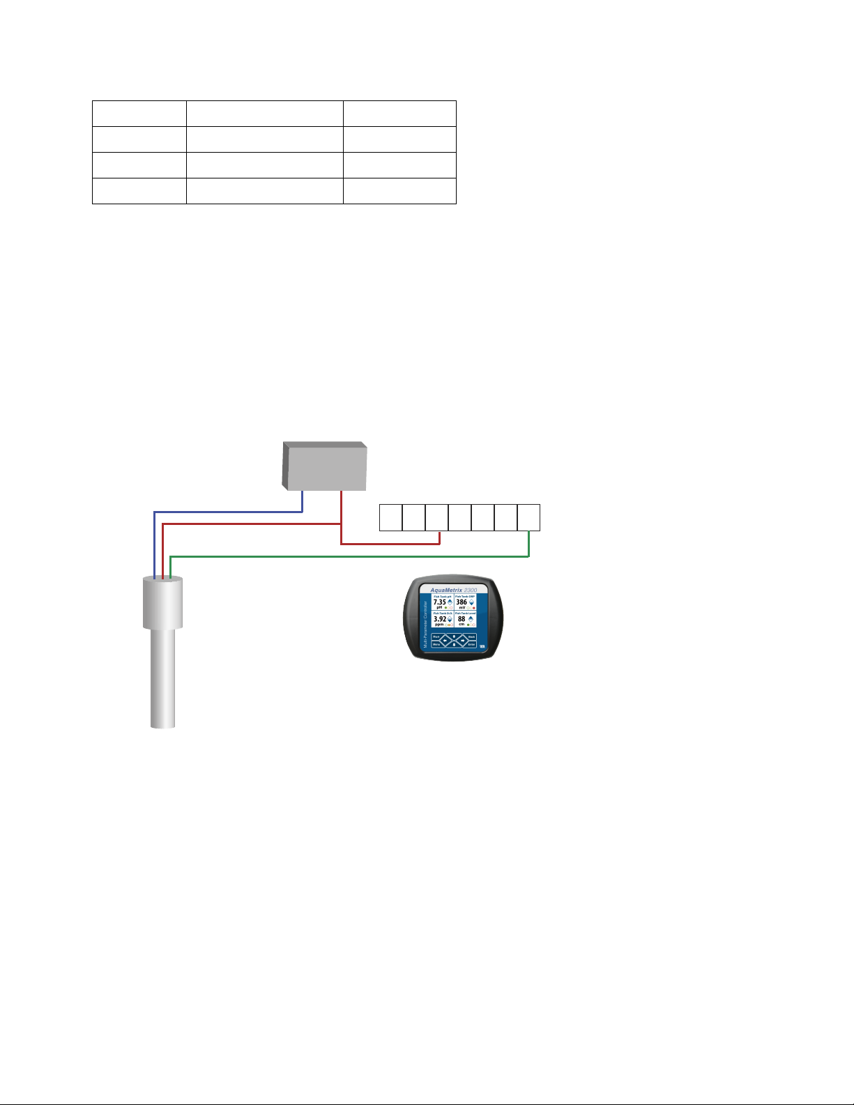
The AM-LDO is a 4-20 mA 3-wire sensor. It is powered by an external 24 VDC power supply. Figure 1
shows the connections between a power supply, the AM-LDO and the AquaMetrix 2300 controller.
The connections to the 2300 are the same as those to any PLC. Note that connections differ from a
traditional 3-wire sensor
Figure 1 - Electrical Connections to the AM-LDO. The 3-wire probe is powered by a 24 VDC power supply.
The connections are shown for the AquaMetrix 2300 but are the same for any PLC.
5 Software Installation
5.1 Downloading the HDM Software
The AM-LDO communicates to a Windows computer using the FDT/DTM framework. This open
environment allows different devices using different protocols (Modbus, Profibus, DeviceNet, etc.) to
communicate through a Windows based PC using one Field Device Tool (FDT) frame. Each device has
its Device Type Manager (DTM).
GND
+24 V
Power Supply
AM-LDO Probe
Green Wire
Red Wire
Blue Wire
24V 24V An1 An4An3An2 Gnd
Analog Connector on the 2300
Signal
24 VDC
Ground
Page 8
AM-LDO Manual, Rev. 1.1
There are three software packages that must be installed to enable Modbus control of the sensor.
They are all found on the Hamilton website page that is currently at:
http://hamiltoncompany.com/products/sensors/c/875/
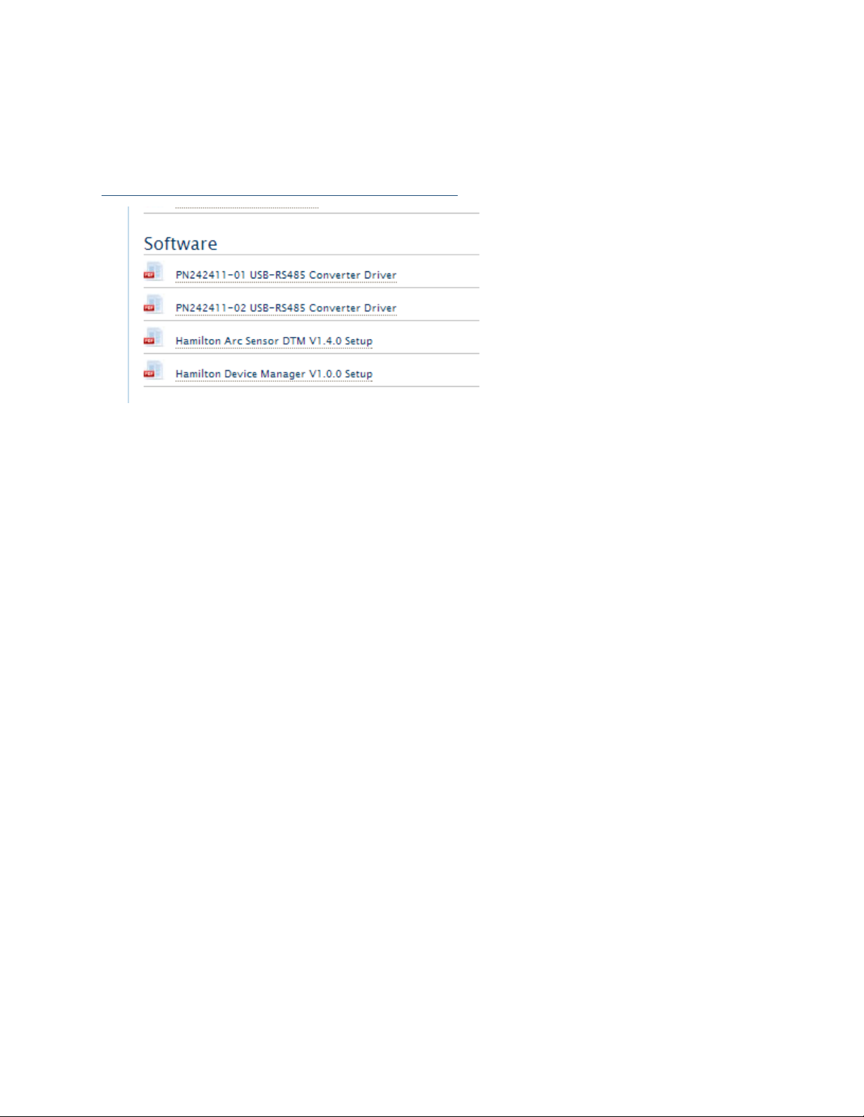
Figure 2 - Section of software download screen for downloading the three software components. Note that
the default driver software for the USB-RS485 converter is PN242411-02 and that PN242411-01 is only for
older adapters.
Click on the tab Downloads and Links to access the software downloads. The three software modules
are:
1. PN242411-02 USB-RS485 Converter Driver is the driver software to convert the RS485 Modbus
signal to a USB signal. PN242411-01 is only for older converters. Other drivers and driver
software may be used, as explained in the next section.
2. Hamilton Device Manager V1.0.0 Setup is the main software for controlling the sensor.
3. Hamilton Arc Sensor DTM V1.4.0 Setup establishes communication between the sensor and
the HDM.
5.2 Installing the PN24211-02 USB-RS485 Converter Driver Software
Hamilton supplies a USB-RS485 adapter which we offer for resale. However any USB-RS485 adapter will
work and the driver software is certain to be found on the manufacturer’s website. In fact, most versions
of Windows since XP will automatically detect any newly installed hardware and search the network for
the corresponding driver software. The following instructions apply to the Hamilton supplied driver.
1. First click on the PN 24211-02 USB-RS485 Converter Driver link to download the zip file. (The
PN242411-01 driver software is only for older sensors.) After you have unzipped the file, you
will have a folder that contains the driver software, CDM20600.exe, as well as a manual. (Note:
We have experienced installation failure using 7-Zip to extract the files.) All Windows
operating systems have a native unzip utility that is accessed by right-clicking on the zip file.
This manual contains the salient steps needed to install the driver software so you should not
need the PN624325-01_USB-RS485-Converter_Manual.pdf that comes with the software
download.
Page 9

AM-LDO Manual, Rev. 1.1
2. Double click on the CDM20600.exe file to install it. This executable file, written by Future
Technology Devices International (FTDI), will install itself. As shown in Figure 3 a terminal
window will briefly pop up and notify you that it installed properly.
Figure 3 - Terminal window showing installation of the USB-RS485 software. It appears very briefly.
3. Insert the USB-RS485 converter into a USB port. The CDM20600 driver should recognize the
new hardware. Depending on your Windows OS, you may get a pop-up message on your
bottom right task bar that the device driver installed correctly and/or that the converter is
ready to use. To verify that the PC did indeed recognize and connect the converter bring up
the Device Manager. You will find the converter’s presence in two places as shown in Figure
4:
a. You will find an item in the Device Manager list, Ports (COM & LPT). If you click on that
list to expand it you will find item, USB Serial Bus Controller (COM X), where X is a port
number. If there are no other devices being used X will be 3.
b. At the bottom of the Device Manager list you will find the item, Universal Serial Bus
Controllers. If you click on that list to expand it you will find the item, USB Serial
Converter (likely at the bottom of that list).
Page 10

AM-LDO Manual, Rev. 1.1
Figure 4 – The Device Manager window on the left confirms that a port (number 3) has been assigned to a
USB Serial Port. The Device Manager window on the right confirms that the
4. Should it become necessary to remove the driver and free up the COM-port, bring up the
Device Manager, right click on Ports (USB & LPT) > USB Serial Port (COM3) and click on
Uninstall. If you wish to keep the driver installed and just release the COM port do not select
the field, Delete the driver software for this device. This will enable the PC to recognize
automatically any future USB-to-RS485 converter.
5.3 Installing the Hamilton Arc Sensor DTM Setup Software
The DTM (Device Type Manager) provides the interface between the sensor and the FDT (Field Device
Tool). The latter is incorporated into the Hamilton Device Manager (HDM). The FDT works seamlessly
with the HDM and is invisible to the user.
The following link downloads the DTM for the AM-LDO sensor.
1. Click on the Hamilton Arc Sensor DTM Setup link on the download page:
(http://hamiltoncompany.com/products/sensors/c/875/)
2. Unzip the downloaded file, ArcSensor DTM 1.4.0_Setup.zip. (Since the writing of this manual
ArtSensorDTM_1.4.0_Setup. The folder contains the executable file, ArcSensor DTM_1.4.0_Setup as well as the DTM_Installation Guide and HDM-DTM Quick Guide. Click on
ArcSensorDTM_1.4.0_Setup to initiate the installation.
5.4 Installing the Hamilton Device Manager Setup Software
The HDM application is Hamilton’s FDT frame application. Note that any FDT frame will work with the
sensor.
Page 11

AM-LDO Manual, Rev. 1.1
1. Click on the Hamilton Device Manager V1.0 Setup link on the download page
(http://hamiltoncompany.com/products/sensors/c/875/)
2. Unzip the downloaded file, HDMI_V1-0-0_Setup.zip. (Since the writing of this manual the
version number of the software may have changed.) This will create the folder, HDM_V1-0-
0_Setup folder. The folder contains the executable file, setup. Click on either HDM_V1.0.0 or
setup and follow instructions of the installation wizard to install the Device Manager.
3. The installation will create the HDM application and, likely, create a shortcut on the desktop.
5.5 The HDM Device Manager
Warning: If your AM-LDO comes with the manual, Visiferm DO ARC Sensors, the identification of the color
coded wires is NOT correct for the AM-LDO. See Table 1 for the correct color code. Also the color code of the
Hamilton labeled USB-RS485 converter is correct for the Visiferm and NOT the AM-LDO.
5.6 Setting up the HDM Device Manager and Sensor
Launch the Hamilton Device Manager (HDM) application. You will see one window in that lists the
status of all devices that communicate through the FDT. In this particular case there will only be one
AM-LDO sensor though more can be added. All sensors are shown as files in a folder in the left hand
window, Network View.
You may see three additional window. On the right side is the Device Catalogue and, on the bottom,
are the FDT Monitor and the Error Log tabbed windows. Both of these are only useful for diagnosing a
connection problem and can be closed in normal operation.
Figure 5 - Initial screen when first starting up the HDM application. The FDT Monitor, Error Log and Device
Catalog windows are not needed except to diagnose a problem and are better
4. If the Device Catalogue, Error Log or FDT Monitor windows are open you can close them so
that you can view the settings for the COM port that communicates with the sensor.
Page 12

AM-LDO Manual, Rev. 1.1
5. To add the AM-LDO go the menu Device and click on Add… (You can also click on the button
Add Device located on the right hand side. You will see the Arc MB (Modbus) Serial Port
already highlighted. Click on the OK button to add the USB-RS485 Modbus Connector. The
other two choices are for Modbus and Hart wireless sensors.
Figure 6, - The first line, Arc MB Serial Port, shows that the HDM frame found the AM-LDO sensor. Click on
the OK button to add it.
6. You will then see a new window, shown in Figure 7. The Device Manager has added the ARC
MB Serial Port to the HDM’s FDT. The new window shows the communication parameters
between the computer and the USB-RS485 Modbus adapter. You may change any of the
communication parameters in this window. If the adapter does not appear in this window,
make sure that the serial port number listed in the upper right corner of the Offline Parameter
window matches the port number listed in the Device Manager’s Ports setting.
Page 13

AM-LDO Manual, Rev. 1.1
Figure 7 - The HDM sets up a connection to the AM-LDO through the serial port.
7. As the window tab name shows, the USB-Modbus converter is offline. You can only change
the COM port communication settings or remove the converter when the device is offline.
The visual cue that a device is offline is that its name is written in a non-bold font. If a device is
online the text changes to a bold font.
8. The next step is to add the sensor to the serial port. You can either navigate to the Device
Menu and click on Add… or right click on the Arc MB Serial Port icon in the Network View
window. When you do you a new window will pop up as shown in Figure 8. Click OK to add
the sensor to the FDT frame.
9. Figure 8 - Window showing the DO sensor connected to the serial port.
Page 14
AM-LDO Manual, Rev. 1.1
10. The Hamilton Device Manager window reappears and the sensor now appears in the Network
View window under the ARC Serial Port listing, as shown in Figure 9. Note that the text for
both the converter and the sensor are both in plain (not bold) text to indicate that they are
offline.
Figure 9- After clicking OK in the Add window the HDM adds the LDO sensor.
11. Now that the sensor is connected to the device manager you bring it online. Either navigate to
the Device menu and click on Go Online or right-click on the sensor listing in the Network
View window and select Go Online. If you make the sensor go online then the Serial Port also
goes online. When the sensor and serial port go online the text in the Network View window
becomes bold.
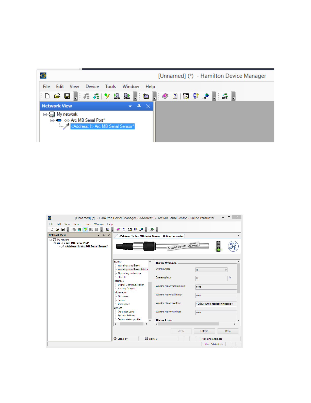
12. Double click on the <Address 1> Arc MB Serial Sensor and you will see the window shown in
Figure 10.
Figure 10 - HDM window showing the AM-LDO sensor. The sensor and the port are both live as indicated by
the bold font in the list view on the left.
Page 15

AM-LDO Manual, Rev. 1.1
Note the traffic light in the upper right corner in Figure 10. The green light means everything is okay. A
yellow light means that a sensor warning has been activated and a red light means that a sensor error
has been activated.
5.7 The Device Manager Menu Bar
The options contained in the menu bar of the Device Manager are mostly self-explanatory. A
searchable manual can be accessed at any point by clicking on the Help menu or the Question Mark
icon. A few notes are in order for some of the more important menu items.
5.7.1 File Menu
The File > Save as command allows you to save the settings in the sensor configuration so that it can
be recalled at a later time.
Info…. provides a space for recording notes that may be needed. For instance, if there are no errors or
warnings during operation it makes sense to close the Error Log window.
5.7.2 Device
Several of the items in the Device menu, such as Go Offline / Go Online are also accessible through
right clicks in the Network View window.
5.7.3 View Menu
The View Menu is a listing of the windows that comprise the Device Manager. You can click on any of
these windows to customize the workspace.
5.7.4 Tools
The Tools menu contains two items: Customize and Options. The Customize menu has two daughter
menus: Toolbars allows you to configure the menu of icon shortcuts in the row just below the top
level menu.
Of greater importance is the Options menu which has several useful functions
• General Options > Language allows one to switch the language to German, Chinese or
Japanese.
Figure 11 - To change the language select Tools > Options > Language. You may select English, German,
Chinese or Japanese.
Page 16

AM-LDO Manual, Rev. 1.1
• User accounts / passwords enables one to restrict permission to four classes of user, which are,
in order of authority level: Observer, Operator, Maintenance and Administrator. You can also
change passwords for each of the four classes of users.
5.8 Configuring the Device Manager
The status window allows the user to view and change settings to the sensor. Most of the settings are
self-explanatory. When changing a setting one must click on the Apply button at the bottom of the
window.
The following section highlights only the settings you are most likely to adjust:
5.8.1 Measurement:
a. Data log / Monitoring enables data logging. The Trace file path allows the user to
change the location of the data file. The trace interval specifies the time between data
points. Choosing On for Record Trace file turns on the data logging.
Clicking on the Refresh button gives an instantaneous measurement reading of the
D.O. and temperature values. (So does Interface > Analog Output 1:Signal.)
b. Measurement Variables allows one to select between units for D.O temperature. The
most commonly units for D.O. are mg/l (or ppm) and % saturation.
c. Measurement Parameters includes all those factors that affect the D.O. reading. A D.O.
sensor can only measure % saturation. It then calculates absolute concentration of
oxygen, e.g. mg/l, using a known value of air pressure. The Air pressure setting should
be changed when the sensor is not at sea level (or if a hurricane is imminent.) The
other parameters control the reporting of data.
5.8.2 Calibration
a. Calibration Zero Point can only be used if the user can insert the probe in a zero D.O.
environment. This can be done by adding a sufficient amount of reducing agent, such
as sodium bisulfite. In most cases, the user simply assumes that zero D.O. corresponds
to a zero reading and skips this step.
b. Calibration Air is the most common, and easiest, way to calibrate. Simply select
calibration option auto in air, hold the probe in air (preferably at or near 100%
humidity) and click on Apply. You may take additional calibration readings by clicking
on the Refresh button. Note that you will not see the actual probe reading; that can
only be done as described in the previous section.
c. Product Calibration allows a sensor to be calibrated without removing it from a
process. It uses a standard calibration curve and a reading from an independent sensor
on a grab sample of the process. It is only rarely used.
Section 7.1 discusses calibration in greater depth.
Page 17

AM-LDO Manual, Rev. 1.1
5.8.3 Status
a. Warnings and Errors is perhaps the most important of all the Online Parameter
options. If the traffic light in the upper right corner turns yellow (for warning) or red
(for error) then the details of either will appear in this section. An example of a warning
is that the probe has not been calibrated/ An example of an error is that the 4-20 mA
output has exceeded 20 mA.
b. Warnings and Errors History is useful for looking back at previous errors or warnings.
c. SIP/CIP (sterilization-in-place and clean-in-place) defines the temperature and
duration that the sensor encounters to enable it to recognize these maintenance
procedures. They are not very pertinent to the water and wastewater industries.
5.8.4 Interface
a. Analog Output 1: Setting maps the usual 4 mA and 20 mA output signal to D.O.
measurements. The usual mapping is 4 mA to 0% D.O. and 20 mA to 100% D.O. The
b. Analog output 1: Signal gives an instantaneous probe reading upon clicking on the
Refresh button.
c. Analog Output 1: Warnings/Errors allows the user to trigger an alarm and/or error
condition based on the 4-20 mA signal.
5.8.5 Information
a. Firmware does not contain any user configurable parameters. Firmware updates are
available on the Hamilton website.
b. Sensor contains only parameters that are set at the factory. They are not configurable.
c. User space enables one to set up user-defined fields. (MORE)
5.8.6 System
a. Operator Level defines levels of permissions. There are four levels:
i. Users (U) can read basic data from the sensor. No password is required.
ii. Administrators (A) can calibrate sensors. A password is required.
iii. Specialists (S) have full access to all of the editable parameters accessed in the
HDM. A password is required.
b. Change Password allows an Administrator or Specialist to change his/her password.
The HDM comes with the followling default passwords:
Administrator – 18111978
Specialist – 16021966
c. Factory Setting allows the user to restore all parameters to their factory settings.
Page 18

AM-LDO Manual, Rev. 1.1
d. Sensor Status Profile writes all of the sensor parameters into a text document that can
be found in C: > Hamilton > DocuSensor.
6 Multiplexing Multiple Sensors
The serial Modbus RS485 interface allows the user to gang multiple sensors through one RS485
connection. Figure 12 shows the connections. A 24 VDC power supply is still needed.
The Modbus connection between the RS485 port and the corresponding interfaces of the sensors has
to be ensured according to the EIA/TIA RS485 standard. Only one sensor can communicate with the
master at any time.
Figure 12 - Multi-drop bus wiring for the Modbus two-wire mode. Each sensor functions as a Modbus slave.
7 Calibration and Maintenance
7.1 Warm-up
The sensor requires a preheating period of 10 to 15 minutes after it is switched on. Although
measurements are possible during this time, you must wait until preheating is complete to be able to
calibrate the sensor optimally.
The concept behind the AM-LDO sensor enables calibration and configuration in the lab before use in
the process control. Another calibration for the installation in the process setup is not required
Page 19

AM-LDO Manual, Rev. 1.1
7.2 Calibration
The AM-LDO provides two kinds of sensor calibration: automatic standard calibration and product
calibration. This section goes into calibration in greater depth than Section 7.2. Both procedures are
found in the Calibration section of the Hamilton Device Manager.
7.2.1 Automatic Standard Calibration
The AM-LDO sensor is calibrated at two points: in air and in an oxygen-free environment. During
calibration, the sensor examines the correctness and stability of the oxygen and temperature signals.
Calibration of the sensor, in most applications, need only be done several times per year.
Calibration at Point 1 (0% D.O.)
(The zero point calibration step is not necessary as one can assume zero output at 0% D.O.)
1. Set an appropriate operator level (Administrator or Specialist).
2. Immerse the sensor into an oxygen-free environment.
3. Let the system equilibrate. This usually requires at least three minutes. For greater
measurement accuracy insure that temperature difference between calibration medium and
process medium is minimal.
4. Take the calibration at point 1 by clicking on the Apply button.
5. The device manager confirms the calibration immediately.
Calibration at Point 2 (100% D.O.)
1. Set an appropriate operator level (Administrator or Specialist).
2. Leave the sensor for at least three minutes under stable conditions in ambient air or in oxygen
saturated medium. An air pump with a diffuser that can be found in any aquarium store works
fine.
3. Take the calibration at point 2 by clicking on the Apply button.
4. The device manager sensor confirms the calibration immediately. The calibration curve of the
sensor is now defined by the recent calibration at both points: 1 and 2.
If you experience measurement value shifts as small as a few percent within a period of a few days,
suspect damage to the lumophore caused by the measurement or cleaning medium. Should this
occur, consider whether more frequent exchange of the sensor cap is acceptable, or whether the
sensor should be placed in a different part of the process.
7.2.2 Product Calibration
The product calibration is an in-process calibration procedure in order to adjust the measurement to
specific process conditions, or in case the sensor cannot be removed for the standard calibration.
Product calibration is an additional calibration procedure to a standard calibration. Product calibration
corrects the standard calibration curve to the process conditions in force at the time of product
calibration. If product calibration is activated, the AM-LDO’s calibration curve is calculated from the
data of last calibration at point 1 and from the data of the product calibration.
In order to restore the original standard calibration curve, the product calibration can be cancelled at
any time. A new standard calibration cancels a product calibration as well.
1. Set an appropriate operator level (Administrator or Specialist).
Page 20

AM-LDO Manual, Rev. 1.1
2. Perform an initial measurement while taking a sample from the process. The data of the initial
measurement are stored in the sensor.
3. Perform a measurement with an independent (laboratory) sensor of the sample at the same
temperature as it was measured in the process.
4. Assign the laboratory value to the value of the Initial measurement.
This new DO value is accepted and instantaneous active, if the difference between initial measurement and
laboratory values is not greater than 20%-sat units.
7.3 Changing the Sensor Cap
Changing the sensor cap is easy: Unscrew the old sensor cap from the shaft.
HINT: If the sensor cap is mounted very firmly on the shaft, and if you cannot obtain a good grip on
the stainless steel with your fingers, a silicone tube between your fingers and metal may supply a
better grip. Examine the small O-ring that seals the sensor cap to the sensor shaft.
Exchange the O-ring, if any traces of wear are seen. A replacement O-ring is included with each
replacement sensor cap.
Screw the new sensor cap onto the sensor shaft again. Make sure that the gap between the shaft and
cap is closed, and that the sealing effect of the O-ring under it is therefore guaranteed. In order to
enable traceability note the serial number of the new sensor cap.
Examine the measurement values of the sensor in air, and if necessary, in an oxygen-free medium. If
the measurement values deviate significantly from operated value, perform a calibration.
8 Errors and Warnings
The AM-LDO can diagnose most common problems through the HDM interface. The Status section of
the Online Parameter window in lists warning errors. The following types of messages are provided by
the self-diagnosis function:
• Warning (alarm):
o DO readings upper/lower range, unstable.
o Temperature readings upper/lower, unstable.
o Calibration recommended.
Page 21

AM-LDO Manual, Rev. 1.1
o Calibration upper/lower, out of range, or unstable.
o Replace sensor cap.
o 4–20 mA output out of range, unstable
o Supply voltage upper/lower range.
• Error (failure):
o Sensor cap missing (reading failure).
o Temperature out of range.
o Temperature sensor defect (reading failure).
o Supply voltage out of range.
9 Products and Accessories
AM-LDO
Optical DO sensor with direct output to 4-20 mA or Modbus RTU
AM-LDO-USB
Converts Modbus over RS485 to USB
Figure 13 - RS485 Modbus USB Converter. (Any RS485-USB converter will work.)
Page 22

AM-LDO Manual, Rev. 1.1
100 School Street
Andover, MA 01810
www.Aquametrix.com
978-749-9949
 Loading...