

Page 1
www.aquacraftmodels.com
m
™
• Never attempt to swim after a stalled R/C boat.
• Never operate your R/C boat while standing in the water.
• Never operate your R/C boat in the presence of swimmers.
• Always use a Personal Flotation Device (PFD) when boarding and operating your retrieval craft, i.e. Jon
boat or duck boat. NOTE: Because of the sharp running hardware included with this R/C boat, we do not
recommend a rubber blow up raft.
• R/C boat running hardware is very sharp. Be very careful when working on and around the metal parts.
• While the motor is running pay close attention to the propeller. Do not come in contact with the propeller at
any time the engine is running or serious injury will result.
• AquaCraft products are to be used by ages 14 and over.
WARNING:
www.aquacraftmodels.com
ww.aquacraftmodels.co
™
Page 2
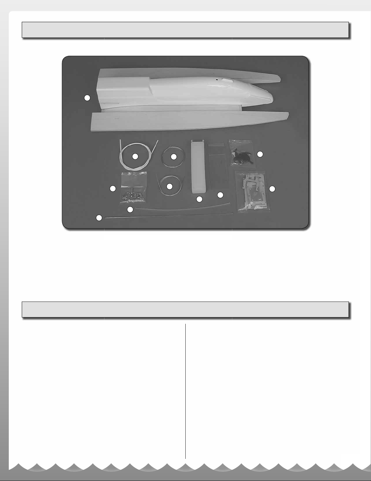
ITEMS INCLUDED
1
2
5
6
7
3
4
1. VS1 Hull and Cowl
2. Throttle Outer Pushrod Tube
3. Throttle Cable (Gold)
4. Rudder Cable (Silver)
5. Screw Bag
6. Antenna Tube
WARRANTY
AquaCraft will warrant your VS1 for 90 days after the purchase from
defects in materials or workmanship of original manufacture. AquaCraft,
at their option, will repair or replace at no charge, the incorrectly made
part. This warranty does not cover damage caused by crash, abuse,
misuse, alteration or accident. To return your boat for repairs you need
to provide proof of purchase. Your store receipt or product invoice will
suffi ce. IN NO EVENT SHALL THE PURCHASER BE ENTITLED TO
ANY INCIDENTAL, SPECIAL, INDIRECT OR CONSEQUENTIAL
DAMAGES, WHETHER RESULTING FROM THE USE, MISUSE OR
INABILITY TO USE THE PRODUCT OR FROM DEFECTS IN THE
PRODUCT. This warranty gives you specifi c legal rights and you may
also have other rights, which vary from state to state. (Outside USA
and Canada, contact local importer for warranty information.)
Hobby Services
3002 N. Apollo Drive, Suite 1
Champaign, Illinois 61822
Attn: Service Department
Phone: (217) 398-0007 9:00 am - 5:00 pm Central Time M-F
E-mail: hobbyservices@hobbico.com
10
11
8
9
7. On/Off Switch Pushrod
8. Fuel Tank
9. Radio Box Cover
10. Hardware Bag
11. Tank Mount Bag
Decal Sheet
STANDARD REPAIR SERVICE
After the 90-day warranty has run out you can still have your VS1
repaired for a service fee by the experts at AquaCraft.™ To speed up
the repair process, please follow these four simple steps:
Important Note: For standard repair service you must specify
whether you wish the charges to be billed COD or if you wish to be
notifi ed of the charges so you can send a check.
1. Please return the ENTIRE system, boat and radio.
2. Make sure batteries are removed from the transmitter.
3. Send written instructions which include a list of all items returned,
a THOROUGH explanation of the problem or problems of the
service needed. Be sure to include your return address and
daytime phone number. If you have access to e-mail please provide
us with your e-mail address to help speed communication.
4. Send to the address above.
2
Page 3

INTRODUCTION
SPECIFICATIONS
Thank you for purchasing the AquaCraft™ VS1! We want
the time you spend with your new R/C boat to be fun and
successful so please fully read the manual. If for any reason
you think this R/C model is not for you, return it to your local
hobby dealer immediately. Your hobby dealer cannot accept
returns on any model after final assembly or after your boat
has been operated.
SAFETY PRECAUTIONS
• Never, ever, attempt to swim after a stalled R/C boat.
Do not get in the water for any reason to retrieve your
boat. To aid you in retrieving a stalled R/C boat, set up a
fi shing reel with a tennis ball tied to the end of the line.
Or better yet, get yourself a small boat so you can row
out and pick up your R/C boat. Remember to use a PFD
any time you enter your retrieval craft.
• AquaCraft products are to be used by ages 14 and over.
• Do not touch the propeller anytime the motor is running.
Pay equally close attention to items such as loose clothing,
shirtsleeves, ties, scarves, long hair or anything that may
become entangled in the spinning prop. If your fi ngers,
hands, etc., come in contact with the spinning propeller,
you may be severely injured.
• The speed and mass of this boat can infl ict property
damage and severe personal injury if a collision occurs.
Never run this boat in the presence of swimmers or where
the possibility of collision with people or property exists.
• Glow engines produce heat. Do not touch any part of your
motor until it has cooled.
VS1 SPECIFICATIONS:
Hull Length: 28" (710mm)
Overall Length: 34-1/4" (870mm)
Width: 11-1/2" (290mm)
Height: 5-1/2" (140mm)
Weight (less fuel): 4lbs, 2oz
VS1 FEATURES:
ARR Pro-built construction
Race-winning heritage
Lightweight wood, foam and ABS construction
High-gloss, fuel resistant, natural wood fi nish
Water-resistant radio box
Molded waterproof radio box cable output
8 oz. molded plastic fuel tank
Pull-pull steering system
BOAT TERMINOLOGY
TUNNEL HULL: Is a style of boat that traps air between two
sponsons to gain lift.
BOW: The front of the boat.
TRANSOM: Aft most structure on the back of the boat.
PORT: This is the left side of the boat when aboard and
facing the front (bow). An easy way to remember this is that
port and left both contain four letters.
STARBOARD: This is the right side of the boat when aboard
and facing the front (bow).
HULL: The body of the boat.
DECK: The top of the hull.
COWL or CANOPY: Removable ABS top.
SPONSON: Left or right structure this type of boat rides on.
KEELSON: The inner side of the sponsons.
SKEG: The rudder blade on your outboard that extends
below the propeller shaft.
• This boat is controlled by radio signals, which are susceptible
to possible interference from other R/C transmitters, paging
systems, or other electrical noise. Before turning your radio
transmitter and receiver on, make sure no one else in the
area is operating a radio on the same frequency (channel).
• In the event that weeds become entangled in the propeller,
stop the motor before attempting to remove them.
• If your VS1 should happen to stall, water currents will slowly
carry it to shore. The bad news is that the boat could be
carried to the opposite shore. When surveying areas to run
your boat, keep variables in mind such as wind direction, size
of the lake, etc. It is not advisable to run R/C boats on any
free-fl owing bodies of water such as creeks or rivers.
MANUAL SPECIFICATION AND
DESCRIPTION CHANGES
All pictures, descriptions, and specifi cations found in this
instruction manual are subject to change without notice.
AquaCraft maintains no responsibility for inadvertent errors
in this manual.
3
3
Page 4
PARTS NEEDED TO
COMPLETE YOUR VS1
RADIO SYSTEM:
• Futaba
Harness (FUTK2020) OR Futaba 4PK 2.4GHz Transmitter,
Receiver and Switch Harness (FUTK4900)
• Steering Servo, Futaba S3305 (FUTM0045), OR Futaba
S9405 (FUTM0098)
• Throttle Servo, Futaba S3115 (FUTM0415) OR Futaba
S3201 (FUTM0034)
• Receiver pack, DuraTrax® 5-cell 6V NiMH (DTXM2011)
• Futaba Receiver Pack Wall Charger (FUTM1705)
• 8AA batteries (transmitter) (3PM Only)
• Boat stand
ENGINE:
• O.S.® 21XM Marine Outboard Engine (OSMG1721)
or equivalent
®
3PM 2.4GHz Transmitter, Receiver and Switch
ACCESSORIES NEEDED TO
OPERATE YOUR VS1
• TorqMaster™ Electric Starter (HCAP3200)
• 30% Boat Fuel (ODOP3130, Quart) or 50% Boat Fuel
(ODOP3150, Quart)
• Hot Shot™ 2 Glow Igniter (HCAP2520)
• Hand Crank Fuel Pump (HCAP3015)
• Fuel Line (AQUB6903)
• Fuel Filter (GPMQ4150)
• Glow Plug Wrench (GPMP2000)
• AquaCraft GrimRacer™ Pro Radio Box Tape (AQUB9514)
• AquaCraft GrimRacer Speed Grease (AQUB9500)
OPTIONAL PERFORMANCE PROPS
• AquaCraft GrimRacer 40x52/3 Metal 3-blade Prop
(AQUB9720)
• AquaCraft GrimRacer 40x53 Metal Prop (AQUB9715)
EXTRA SUPPLIES
As with any hobby, it is a good idea to assemble a useful
collection of tools and accessories to bring along when
you head to the pond. Here are some items you will want to
keep handy:
Extra “AA” batteries
Extra glow plugs
Spare prop
Small standard screwdriver
Hobby knife
Hex wrenches
Waders or rubber boots
Paper towels
Spray-on cleaner
Sunglasses
Sun block
Folding table
Lawn chair
First-Aid kit
Cooler with plenty of ice and water
Canopy or shelter
TOOLS NEEDED TO COMPLETE
YOUR MODEL
• Soldering Iron
• Solder
• Small Phillips Screwdriver
• 5-64 Hex Wrench
• Needle Nose Pliers
• Hand Drill
• Drill Bits
• Silicone Sealer
• Masking Tape
• 12-Minute Epoxy
• Denatured Alcohol
• Paper Towels
• Rotary Tool with Cut-Off Wheel
• Side Cutters
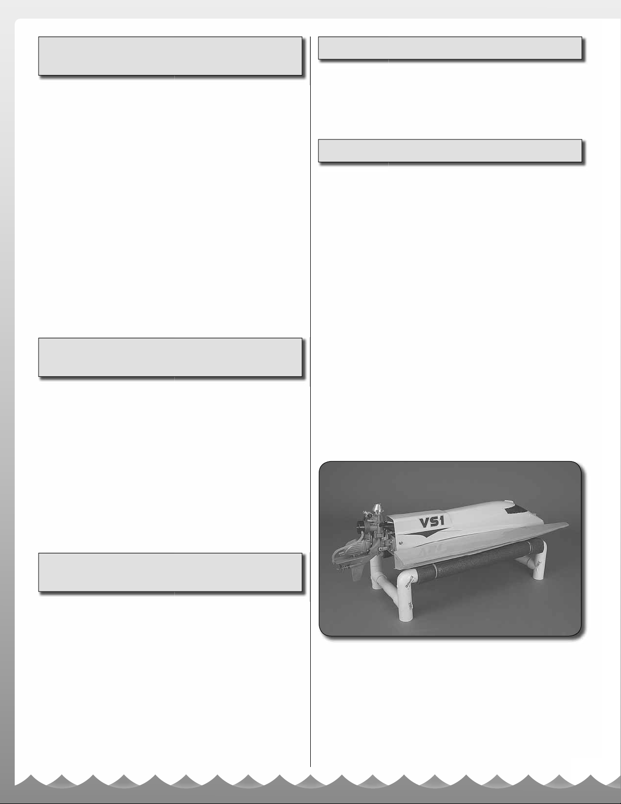
Your VS1 does not include a boat stand. You can build one
out of wood or make one from PVC tubing that you buy from
your local home store.
4
4
Page 5
ASSEMBLY
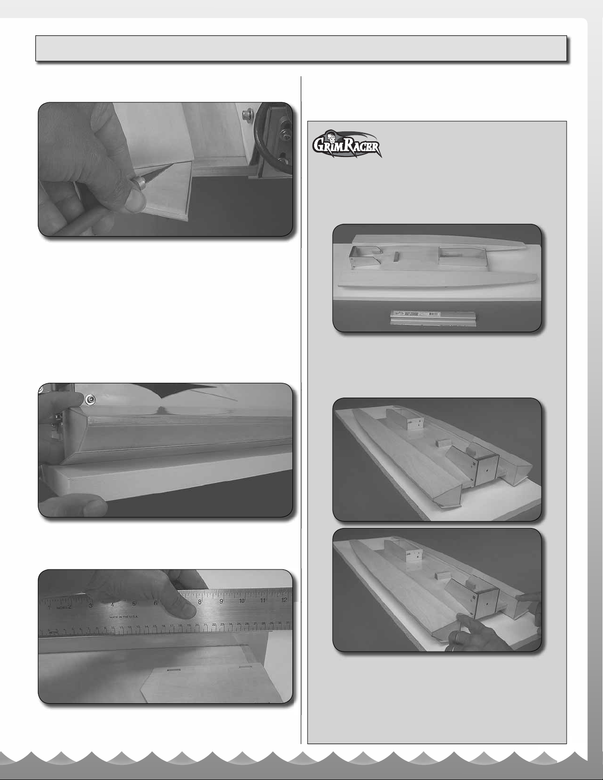
INSPECT THE HULL
1. Check the hull for any open gaps in the seams. We have
done our best to make sure the seams are closed, but it is
still necessary to check it over. I like to use the tip of a hobby
knife to probe around the seams. If you suspect a seam
might be open or allow water to enter the structure you need
to seal it. It is best to do this with 12 minute epoxy. Mix a small
amount of epoxy and work it into the seam using a razor
blade or small acid brush. Keep some denatured alcohol and
paper towel handy to wipe away any excess epoxy. It is also
a good time to look for any exposed wood and seal it from
the water, including the wood parts of the cowl.
and a long, fl at sanding block. Keep the bottom edges sharp
and re-seal any exposed wood. TAKE YOUR TIME! The
fi nished sponsons must be parallel to each other and fl at.
Grimracer says: Blueprinting is the
process of straightening and/or matching
parts. When we talk about blueprinting
the bottom of your VS1, we are mostly talking about the
bottom of the sponsons. Your VS1, like other hand built
performance boats, will likely need to be trued (blueprinted)
get maximum performance.
To do this, you are going to need an 11" sanding bar with 80
grit sandpaper as well as 220 grit sandpaper; a fl at surface
from which to base your progress; as well as some sealer to
re-seal any areas of clear coat you might sand through.
2. Place the boat on a fl at surface and check the alignment
of the sponsons. Your sponsons should be parallel to each
other and touch the fl at surface at the same time.
3. Place a straightedge on the bottom of each sponson (ride
pad). Make sure the last 10"-11" are fl at. If not, you can
“blueprint” them - or make them identical - using sandpaper
To begin, set the boat on your fl at surface and put fi nger
pressure on the top back sides of the sponsons. We need to
do this to see if the two sponsons are parallel to each other.
If the boat rocks from side to side AT ALL, it’s best to match
them. Also take a look down the length of each sponson.
The sponsons work best if they are dead fl at from the back
of the sponsons to around 11" forward of that point.
5
Page 6

If your boat’s sponsons are not parallel to each other, you
will have to decide which sponson needs to be changed. I
like to pick the sponson that is lower in back and work this
sponson forward to match the other.
Load your sanding block with 80 grit sandpaper and place
it on the lower sponson. Start removing material off the
sponson, making sure you keep the sanding block fl at.
Check your progress often and work slowly. Be careful not
to round off any of the edges on the bottom of the boat.
They need to remain sharp.
DRILLING THE TRANSOM FOR THE ENGINE
Parts list and tools needed for this step:
Engine mount template (back cover of this manual)
Hand drill 3/32” drill 5/32” drill
Masking tape Toothpick Epoxy
Carefully cut the engine mount template out from the back
of this manual. Position it on the back of the transom using
tape to hold it in place. Using a 3/32" drill bit, drill the On-Off
hole location as well as pre-drill the holes for the motor mount
bolts. Switch to the larger 5/32" bit and re-drill the four motor
mount bolt locations. Remove the pattern and do your best to
seal the holes using epoxy and a toothpick. After the epoxy
has cured it’s a good idea to pass the appropriate drill bit back
through the holes to clean out any excess epoxy buildup.
Once you have the two sponsons parallel it’s time to move
on, making sure the sponson bottoms are fl at. You will
have noticed that the sponson that you just sanded had
some low spots; if you did not get all the low spots out do
your best to remove them, making sure you do not change
the sponsons’ angle. Once that sponson is completely fl at,
sand the other sponson bottom fl at as well. Finish up with
some 220 grit sand paper.
After you have both sponsons parallel to each other and
the bottoms are dead fl at, you will have to reseal the bare
wood. I like to use clear catalyzed auto paint but a good
fi nishing epoxy works well, too. Note: Avoid laminating
epoxies for this process.
After the sealer is cured, scrape the sponson bottoms fl at
with a single edge razor blade. If you need to apply more
sealer do so now. When that is cured, repeat the scraping
process and fi nish by scuffi ng the sponson bottoms with a
red scratch pad.
INSTALLING THE CABLE OUTPUT, SERVO
TRAY AND SERVOS
List of parts and tools needed to complete this step
(Collect the parts and supplies you need and let’s get
started. This step goes quite fast.):
Output (VS1 Kit)
Eight 2 x 8mm wood screws (VS1 Kit)
Servo Tray (VS1 Kit)
Throttle servo Steering servo Switch harness
Hand drill 1/16" drill bit 5/64" drill bit
Small tube of silicone sealer
4. Test fi t the cowl and make sure there is foam fl otation in
the front. Again check for any exposed wood and seal it at
this time if needed.
1. Place a small amount of silicone sealer onto the back of
the output and screw it into place on the back of the radio
6
6
Page 7

box using four of the 2 x 8mm wood screws. Be careful not to
get any silicone sealer into the small holes in the output that
the cables pass through and do not over tighten the screws.
2. Next take a 5/64" drill bit and carefully over drill the small
hole that passes through the fi nger lever of the on/off switch.
ASSEMBLING THE PULL-PULL WHEEL
This step requires the following kit parts and tools:
35mm pull-pull wheel (VS1 Kit)
Five 2 x 6mm machine screws (VS1 Kit)
Five 2mm machine nuts (VS1 Kit)
.049" pull-pull silver cable (VS1 Kit)
35 mm servo wheel (FUTM2000, comes with most standard
size Futaba servos)
Hand drill
5/64" drill bit
3. Install the switch harness onto the servo tray, making sure
that the switch is positioned on the starboard side of the tray
and that the off position of the switch is towards the back of
the boat. For safety reasons you want to have your switch
“PUSH” to turn the boat on. Slip the servo tray into the radio
box. Use four of the provided 2 x 8mm wood screws to hold
the tray in place. Install the rubber grommets and eyelets
(eyelets slide in from the bottom) onto the servos and place
the servos into the proper openings. Do your best to center
the servos in the opening so the sides of the servos do not
touch the edge of the wood. Using a 1/16" drill, pre-drill
the holes in the servo tray for the servo attaching screws.
Screw the servos in place using the screws provided with
the servos, being careful not to over tighten. Make sure you
have the output shaft positioned towards the front of the boat
on the steering servo and the output shaft to the port side on
the throttle servo.
1. Place the Futaba 35mm servo wheel over the top of the
pull-pull wheel. From the bottom side drill fi ve matching holes
into the Futaba servo wheel that coincide with the fi ve bolt
holes in the pull-pull wheel.
2. Test fi t, and bolt the two parts together using the provided
M2 screws and nuts. Do not fully tighten the parts as we are
just checking the alignment of the holes you drilled. Remove
the screws from the assembly and install the pull-pull cable. To
do this grab the cable and make a small loop in the center of it.
Slip the loop into the recess in the pull-pull wheel as shown.
7
Page 8

3. Carefully reinstall the Futaba servo wheel back over the
top of the pull-pull wheel and reinstall the screws and nuts.
You can place a small dab of thread lock on the screws
before tightening them down. Also, it is not a bad idea to use
a small amount of epoxy in the area the cables cross over
each other to keep them from slipping during operation.
INSTALLING THE ON/OFF PUSHROD WIRE
This step requires:
On/Off rod wire .069" dia. 16" long (VS1 Kit)
3/32" collar with M3 set screw (VS1 Kit)
Needle nose pliers
1.5mm hex wrench
1. Slip the wire through the on/off hole in the output of the
radio box. You are going to want to do this by inserting the
wire from the inside of the box through the cable output.
Temporarily remove the steering servo and 4 screws that
hold the servo tray into the box. Slip the tray forward but do
not remove it. Slide the bent end into the hole you enlarged
into the switch.
2. Carefully slide the servo tray back into position, taking
note the on/off pushrod wire needs to exit the transom you
drilled earlier. The wire will fl ex around the tank mount block.
Install the small lock collar on the end of the wire to complete
this step.
Grimracer says: One way to protect
your on/off switch from accidentally
being turned on or off is by clipping the
wire to just 1" long after it exits the radio box. This shorter
inside switch position requires you to unscrew the cowl
before and after each run but makes the on/off switch less
susceptible to accidental bumping.
In the future if you decide you would like to move the switch
back out through the transom, this can easily be done by
saving your cut-off length of wire and binding the two wires
together using a 5/32" locking collar (not included).
8
Page 9

INSTALLING THE ENGINE
Parts and tools you are going to need:
Engine
Four 6-32 x 1" Socket head bolts (VS1 Kit)
Four #6 washers (VS1 Kit)
Metal backing plate (VS1 Kit)
7/64" hex wrench
ASSEMBLING THE FUEL TANK MOUNT
1. Take a few moments to study the parts layout in the picture.
You will notice that one end of the base plate has holes in
it and the other end does not. The upright with the shorter
bottom legs glues to the end of the base plate without the
holes. The part fi t is tight; if needed, fi le or sand the slots a
bit larger for more clearance.
Place the motor against the transom. Set the metal backing
plate inside the motor box. Using the 6-32 bolts and washers,
bolt the motor to the transom. The metal backing plate is
tapped to the correct size so there is no need for lock nuts.
At this time there is no need to adjust the height of the motor;
we will get to that during the “Hull Tuning Tips” section (page
15) of this manual.
2. Using 12-minute epoxy, glue the center spine to the
base plate.
3. Epoxy the rear (short) upright into the slots in the back of
the base plate.
9
Page 10

4. Next, epoxy the front (longer) upright into the base.
INSTALLING THE FUEL TANK
Parts and tools you are going to need:
Pre-built mount (VS1 Kit)
Four 2 x 10mm wood screws (VS1 Kit)
Small Phillips screwdriver
Fuel tank (VS1 Kit)
O-rings (VS1 Kit)
Fuel line
5. To help strengthen the area that the O-rings attach to, it is
a good idea to place a few drops of thin CA on the hook end
of the uprights.
6. The completed mount.
1. Align the fuel tank mount’s front tabs in front of the forward
mounting block. Screw the mount in place using the four
2 x 10mm wood screws provided.
2. Carefully slip fuel line onto each fi tting on the fuel tank.
Place the fuel cell in the mount cradles and secure with the
included O-rings. If you like, you can cut the fuel line to length.
When doing so, make sure you have enough line length to
place the lower fuel line to the carburetor and the upper line
to the muffl er pressure. Note: Please use a fuel fi lter from the
tank to the engine carburetor.
10
Page 11

INSTALLING THE STEERING CABLE SYSTEM
Parts and tools you are going to need:
Assembled pull-pull wheel Safety glasses/goggles
Two clevises (VS1 Kit) Soldering iron
Two 2-56 nuts (VS1 Kit) Solder
Two threaded couplers (VS1 Kit)
Two 1/4" lengths of fuel line (VS1 Kit)
Rotary tool w/cutoff wheel
1. Position the pull-pull wheel so that the Futaba wheel is
facing up and the cable is towards the back of the boat. Slide
the cable through the small holes in the back of the output.
Place the pull-pull wheel on the steering servo and align the
wheel so the cable is centered on the servo.
4. Using a rotary tool and safety glasses, cut the cable on
the marks. Install the end of the cables into the threaded
couplers and solder them together. Repeat this on the other
side. Slip the short lengths of fuel tube up over the clevis.
This will help keep the ends from popping off in the event of
a blow off or rollover.
Grimracer says: When installed, the
cables will touch the fuel tank mount.
This is OK and will not cause any binding
in the system.
2. Screw the nuts onto the threaded couplers, then the
couplers onto the clevises to the point where you have an
even amount of threaded portion showing both front and
back. It’s a good idea to install the short length of fuel line
onto the clevis at this time so as not to forget.
3. Clip the clevises to the outermost holes on the engine’s tiller
arm. Make sure the servo wheel and tiller are centered. Then,
place a mark on the cable so you know where to cut it.
This is also a good time to place a small amount of cable
grease on the steering cables and on/off wire where they
exit the output guide.
11
Page 12

INSTALLING THE THROTTLE CABLE
Parts and tools you are going to need:
Outer white sheath (VS1 Kit)
Inner metal cable (VS1 Kit)
Four metal clevises (VS1 Kit)
Four threaded couplers (VS1 Kit)
Four 1/4" lengths of fuel line (VS1 Kit)
1/2" length of fuel line (VS1 Kit)
Two zip ties (VS1 Kit)
Rotary tool with cut off wheel
Soldering iron
Solder
Side cutters
Small Phillips screwdriver
2. Cut the outer white sheath to 16" long. Slip the 1/2" length
of fuel tubing onto the large protruding barrel of the output.
Then, slide the white sheath inside the output. Secure the
white sheath to the output by using the two provided zip ties.
1. Using a pair of side cutters prepare the throttle servo horn
by clipping away three of the four protrusions. I like to keep
things neat so I sand away any sharp edges that the side
cutters leave.
3. Insert the other end of the white sheath into the cable
clamp that comes with your motor and tighten.
4. Solder the metal clevis to one end of the steel cable;
slide the cable into the outer sheath from the radio box side.
Attach the metal clevis to the servo horn and position the
horn parallel with the servo.
12
Page 13

5. Next slide the short length of fuel line over the clevis so
as not to forget it. Temporarily slide the clevis over the metal
cable and attach to the throttle arm of the motor. Position the
throttle arm so the carburetor barrel is half open.
POWER UP AND FINAL SET UP
Parts and tools you are going to need:
Small Phillips screwdriver
Clear plastic radio box cover (VS1 Kit)
Antenna mount and tube (VS1 Kit)
Hand drill
1/4" drill bit
Silicone sealer
1. If you have installed the servo horn screws, remove them
at this time. Pull the servo horns off the servo output shafts
and power up the radio. Allow the servos to center. If you
are using a multiple memory radio system, select a model
and rename your model VS1. Reinstall the servo horns and
check the directions and centering of the servos. Adjust the
throttle linkage so that you can fully open and fully close the
carburetor. Remember, you MUST be able to stop the engine
with the radio system or you could risk a disqualifi cation (DQ)
in one of your heats.
6. Place the threaded coupler along side the clevis and mark
the approximate location to cut the cable. Using a rotary
tool and cut off wheel cut the cable at the mark. Solder the
threaded coupler to the cable and install the clevis.
2. Pick a location in the top of the clear plastic radio box
cover and drill a 1/4" hole through it. Using a small amount
of silicone sealer place it around the base of the antenna
mount and bolt in place. You can fi nger tighten the nut on
the back side or use a 10mm wrench, but be careful to not
overtighten the nut.
3. If you are using the latest 2.4GHz technology, you can
shorten the antenna tube that exits the radio box by cutting it
down. Caution: Do not cut the antenna wire from the receiver.
Also, if you are using 2.4GHz you can just let the antenna fold
back as you slide the cowl in place. If you are using 75MHz
technology, you are going to have to drill a corresponding
hole in the top of the cowl to allow the antenna to protrude
through the top.
13
Page 14

TAPING THE RADIO BOX LID
3. Finish by taping the sides. Check again to make sure
you’ve pressed all the tape fi rmly in place, and you’re done.
Remember: After running the boat, pull up the tape to remove
the lid and unplug the battery from the switch.
PAINTING TIPS
1. Start at the back of the radio box. Place tape so that half is
on the clear plastic top and the rest hangs over the side. Fold
the corners down, then press down fi rmly on the top and the
back side of the box.
SAFETY FIRST!
1. Always use a dust mask when sanding and a respirator
when painting.
2. It is required to have access to a proper spray booth or
outside ventilation.
3. You must wear protective gloves when painting and
working with chemicals.
4. If you are not willing to follow the above steps, do not
proceed with painting your boat.
To save weight the main hull and sponsons are best not
painted. However, to make the boat easier to see on the
water and to help protect the cowl from the elements, you
can paint it. Here are a few tips on painting your cowl. I will
list out a quick and easy way to paint the cowl as well as a
more professional way to paint the cowl.
QUICK AND EASY
Quick and easy paint supplies:
White Primer, Top Flite® LustreKote® (TOPR7527)
Color Paint, Top Flite LustreKote (TOPR7502 – TOPR7518)
Clear Top Coat, Top Flite LustreKote (TOPR7501)
Stick (to hold cowl when applying paint)
Double-sided tape
Isopropyl alcohol
Lint-free cloth
2. Repeat at the front of the box.
1. Follow the recommended usage on the paint cans for
proper application.
2. Prep your cowl by installing a paint fi xture of some type. I
like to use a 36" length of 3/4" square dowel (paint stick).
14
Page 15

3. Wipe the cowl down with isopropyl alcohol to remove any
fi ngerprints or other oils. Allow the alcohol to completely
evaporate.
4. Prime the cowl using LustreKote white primer.
5. Paint the cowl with the LustreKote color of your choice.
6. Clear coat the cowl using LustreKote clear top coat.
7. Add some decals and you’re set to go!
Sounds simple and it is. This is a great way to add a personal
touch to your VS1!
PROFESSIONAL FINISH:
Supplies you will need:
Spray equipment (i.e. compressor, spray gun)
Stick (to hold cowl when applying paint)
Double sided tape
Ta c k ra g
Lint free cloth
Fine line masking tape
Painter’s masking tape
Sandpaper (320 wet/dry)
Red scratch pad
Two part automotive primer/surfacer
Two part automotive color (your choice/s)
Two part automotive clear top coat
Let’s get started! Prep your cowl by installing a paint fi xture
of some type. I like to use a 36" length of 3/4" square dowel
(paint stick). You can get a length of wood like this at either
your local hobby shop or your local home store. Take some
double-sided tape and place a 10" to 12" length of it onto the
stick. Remove the backing and attach the stick to the inside
of the cowl. The longer stick makes a great handle to turn the
cowl as you paint.
Prep the cowl by wiping it down with a lint-free cloth and
isopropyl alcohol. Allow the alcohol to completely evaporate
before going any further. Using the red scratch pad scuff
the cowl to remove the gloss. Clean again with the isopropyl
alcohol and allow time to dry. Do not touch the cowl after
this step. Mix up some primer using the mixing ratios that
come with the primer. Prime the cowl starting with a light tack
coat followed by a slightly heaver coat. No need to go to a
full wet coat when using primer, as we are not going for the
ultimate fi nish but rather good adhesion. After the primer has
dried, inspect for any imperfections. Use the 320 sandpaper
on a sanding block to fl atten any high spots or imperfections.
Re-spray any areas that need to be touched up.
After the primer is fully dry, mix and spray the color. With
the color, you are looking for good adhesion and uniformity.
Begin by spraying a light tack coat. After the solvents have
fl ashed off apply another tack coat, wait just a few minutes
and apply a full wet coat. Be careful to avoid any runs in the
paint. After the color coat has fully cured, you can add details
like painting the windshield area or any fancy designs you
might like to try. I like to paint my windshield a medium gray
with a black anti-glare fade near the top. I also like to add
more than one color. Grimracer Says: Odd numbers of base
colors look better than an even number of colors. In other
words, 3 colors look better than 2 or 4.
After the color coats have cured, mix up your clear coat.
Spray the fi rst coat on using a light to medium coat. Wait for
the paint to fl ash off and apply another medium weight coat.
After you have that medium coat applied, wait approximately
5 minutes and apply a full wet coat. Be careful to avoid runs
in the clear. Move the cowl around in the light to look for any
dry spray or runs, adjust or add more paint if needed. If you
take your time you will be rewarded with a very long lasting,
tough and great looking paint job for years to come.
LAUNCH PROCEDURE
Before running the engine, read the instruction manual that
came with your engine.
1. Turn the transmitter on and then the receiver, in that order.
2. Start the engine. It is important to note, the propeller will
start spinning as you start the engine. Be sure to keep
clear of the propeller.
3. Once the engine is running and you are safely at the water’s
edge, launch the boat with a slight forward motion, applying
a slight amount of throttle as you release the boat.
4. Advance the throttle, taking note of the forward track of
the boat. Use the steering trim adjustment knob on your
transmitter to adjust the track of the boat.
5. When you are ready to bring the boat in, drive it parallel to
shore and push back on the trigger to stop the engine. Never
bring your boat to shore by driving it straight at you. Always
drive parallel to shore, stop the motor and then retrieve the
boat. This way if for some reason your engine does not kill
you can still go around and make another attempt.
ENGINE MAINTENANCE
When you are done running your VS1 for the day it is
important to properly maintain the engine.
1. Remove any fuel from the tank.
2. Remove the glow plug from the engine.
3. Open the carburetor.
4. Fill the carburetor with after run oil.
5. Place a rag over the head of the engine and apply short
bursts to the starting cone with your electric starter to coat
the inside of the engine. Repeat this step a few more times.
6. Reinstall the glow plug.
7. Remove the stub shaft from the lower unit and slide out
the cable. Re-grease the cable and reinstall.
When you are ready to run the boat again, remove the plug
and turn the engine over with the starter. Try to remove as
much oil as you can before restarting your motor.
15
Page 16

CARE AND MAINTENANCE
• If you should happen to drip or spill fuel on the fi nish of your
VS1, carefully wipe it off as soon as you can. Some fuels,
especially high nitro fuels and some with special oil additives,
can damage your boat’s fi nish.
• Open the radio box and unplug the battery from the switch
harness. Leave the lid off the radio box over night to make
sure any water that might have entered can evaporate.
• Clean the exterior of the boat and check the mounting
hardware.
• After a few runs and things have had a chance to settle you
are going to have to re-tighten the pull-pull cables leading
to the motor. There is no need to overtighten the cables.
I have found that even a fair amount of slack cannot be
detected when the boat is running.
• If you should happen to fl ip your VS1 you are going to need
to remove any water that might have entered the engine.
We recommend removing the glow plug and turn the engine
over a few times by hand to remove water. After most of
the water has been removed, leave the glow plug out and
turn the engine over with the electric starter to expel the
rest of the water. Make sure you hold a rag over the glow
plug hole. NOTE: Be careful to keep your rag and fi ngers
away from the spinning prop. Re-install the glow plug and
start the engine. It is best to start the engine after you have
fl ipped the boat to make sure ALL THE WATER IS OUT OF
THE ENGINE. It is also a good idea to inspect the radio box
to make sure no water entered the radio compartment.
HULL TUNING TIPS
The major tuning areas of your VS1 are:
• Propeller shaft (stub shaft) height
• Propeller shaft (stub shaft) angle
• Hinge Pin Angle
• Center of Gravity (C.G.)
• Propeller
Let’s start with propeller shaft height. To simplify, what we
are trying to do with propeller shaft height is to raise the
propeller to a height that gives us the greatest speed with the
least loss in stability. Let’s expand on this.
To measure the height of the shaft most racers use a set
up board. A typical tunnel hull set up board can be a simple
piece of shelf board with a slot cut into one end so the user
can reference the height of the prop to the bottom riding
surface of the sponsons.
Adjusting the shaft height plays a huge part in the speed
as well as the handling of the boat. Typically adjusting the
propeller higher makes the boat run faster but at a greater
risk of blowing off the water (fl ipping over backwards). It
also can cause loss of steering in the corners if set too high.
Lowering the shaft has the opposite effect and makes the
boat more stable but considerably slower. It is also important
to note that having the shaft too low can cause the boat to
stuff or tuck under when going around the corner. Setting
the shaft (prop height) is a very important part of tuning your
boat. It is also good to note that even 1/16" higher or lower
can make or break a good running tunnel boat.
Propeller Shaft Angle: Changing the propeller shaft angle
causes the bow of the boat to either run higher or lower
depending on the angle. What we are trying to accomplish
by changing the shaft angle is to loosen up the boat on the
water to make it go as fast as possible. More positive (+)
shaft angle lifts the bow, causing the boat’s tunnel to capture
more air, hence less drag and more speed. The risk of having
too much positive shaft angle is the possibility of blowing the
boat off the water. Too much negative (–) and the boat will
run too wet. Typical modern R/C tunnel boats run with about
1/2° of negative (–) shaft angle.
Hinge Pin Angle: Not all outboard engine mounting systems
allow you to change the hinge pin angle separately from the
stub shaft angle. It is worth noting, however, that outboard
engines that do have a distinct advantage over the ones that
don’t. Let me explain. When the servo swings your engine
left or right, the stub shaft follows the arc that the hinge
pin has been set at. If you have a positive hinge pin angle,
your stub shaft swings in a positive, neutral, positive motion
( + 0 + ). If your hinge pin angle is set negative, your stub
shaft swings in a negative, neutral, negative motion ( – 0 – ).
It’s important to note this, as the more positive angle the
hinge is set at the higher the bow raises in the corners and
the opposite regarding negative pin angle. These can be a
huge tuning advantage for the way you drive. To adjust the
hinge pin angle you must shim either the top or the bottom of
the engine mount plate from the transom. Also: You are going
to want to avoid engine mounts that set the hinge pin past the
back of the sponsons. Having the pin in front of the sponson
we call under steer and behind the back of the sponsons over
steer. The VS1 likes the pin in the under steer position.
Center Of Gravity (C.G.): The center of gravity “balance” of
your boat is just as important as other adjustments you make.
Adding or removing weight from the front of the boat ultimately
decides the stability of the boat as it fl ies over the top of the
water. The further forward you have the C.G., the more speed
the hull can handle, but like other adjustments to your boat
it comes with a price. As a model tunnel boat operates, the
boat’s ride can become disrupted. Any “acting forces” (i.e. wind,
waves, drag and or acceleration/deceleration) can cause the
boat to lose its balance. A properly set C.G. gives you the best
overall balance regarding all those changing conditions.
Propeller: First and foremost you need to balance or use
a balanced propeller. Not only will this provide the best
performance but it is necessary to avoid damaging your
engine. You can learn more about how to balance your
propeller at www.aquacraftmodels.com
16
Page 17

The propeller is probably the most important aspect of how
fast your boat goes and or how well it handles. A poor handing,
slow boat can become an instant winner just by using the
right propeller. As a rule of thumb, non-lifting propellers are
best suited for your tunnel hull. Some lifting propellers can
work but typically need to be “re-worked” to make work well
on a Tunnel Hull. For the best overall performance stick with
a low lift propeller like the AquaCraft GrimRacer 40x53 or
AquaCraft GrimRacer 40x52/3. Testing your propeller is best
done with a stop watch. The most important reading is the
time the boat takes to go from buoy one (1) to buoy three
(3) IMPBA and buoys one (1) through fi ve (5) NAMBA. The
second most important time to capture is overall lap speed.
Your boat may sound or look faster with a prop change
but don’t let that fool you. Course timing is the best way to
determine what if any changes your prop change as made.
Rudder Defl ection: Your VS1 needs very little rudder
defl ection to make it around a corner. Obviously your boat will
turn tighter with more rudder defection but the truth is this can
upset the boat in the corners. It is best to have just enough
rudder defl ection to make a nice sweeping corner PLUS just
a tad tighter. To set the amount of rudder defl ection, run your
boat on the race course at half throttle. Adjust the steering
dual rate until the boat makes a nice sweeping corner a few
feet off the buoys. Next: Run the boat at top speed (remember
to lift off the throttle just a little going into the corner) and
drive the course. Add in more dual rate until the boat runs
the course smooth and fast. Give a few more clicks on the
dual rate adjustment. The extra movement might be needed
to get you out of danger in the middle of a race.
VS1 BASIC SETUP PARAMETERS:
Motor Height: .200" Center of the prop shaft to
the bottom of the sponsons
Propeller Thrust Angle: .5° Negative
Hinge Pin Angle: Parallel to the transom
C.G. Range: 7.5" (27%) to 8.6" (31%) from
the back of the sponsons
Prop: 40x52/3 (AQUB9720)
Rudder Defl ection: 1-3/4" left – 1-3/4" right
DRIVING AND RACING TIPS FROM
12-TIME NATIONAL AND
WORLD RACING CHAMPION
MIKE "GRIMRACER" ZABOROWSKI
Your VS1 makes a fantastic Sport Class racing boat. The
VS1 was designed ultra light to take full advantage of low
power stock style motors. The VS1 is fully capable of wining
races against boats with a lot more power.
Grimracer says, “Don’t just drive your VS1 around, drive
your VS1 around something!” To reach the full potential
this boat has to offer, you need to get it on the water running
around the race course. Running your boat on the race
course allows you to build depth perception as well as get to
know the needs of the boat.
The VS1 responds best if you drive it as if you were driving
a car or any other type of wheeled vehicle. Your lap times
will go down if you lift off the throttle and set the boat as you
enter the corner and accelerate out. Driving “white knuckled”
you will likely not be paying attention to your entry point,
losing valuable seconds off your lap time.
If the pond you test at has an elevated driver’s platform,
make sure you stand on it even during testing. Also stand
in multiple locations. This way if you do not get your favorite
spot on race day you will not be surprised by what you
experience. It is also good to take a quick look at the water
and race course before you launch the boat for your heat. If
you see a buoy out of place or an obstacle in the water it’s
best to identify it before you launch the boat.
Starting and launching the boat later in clock time is far
better than starting and launching at the beginning. If your
clock time is 2:30 like most, be warned, if you go out early
you are adding to the seconds your boat can get into trouble.
During the race it’s best to be on the water ONLY as long as
you need to be.
Also have your caller show you the back of the boat before
he or she launches it. Move your rudder back and forth and
make SURE it is working before the boat is launched.
The VS1 was designed for the use of “stock” or “sport”
outboard motors. The ultra light weight of the VS1 and long
fl at section on the sponson bottoms take full advantage of
the lower power stock motors have. We do not recommend
the use of a modifi ed (piped engine) on this hull.
17
Page 18

Precision Prop Balancer
Precision Prop Balancer
ORDERING REPLACEMENT PARTS
To order replacement parts for the AquaCraft VS1 use the
order numbers in the replacement parts list that follows.
Replacement parts can be purchased from your local hobby
shop or by mail order. If you need assistance locating a
dealer to purchase parts, visit www.hobbico.com and click
on “Where to buy”. If you are missing parts, contact Hobbico
Product Support at:
Phone: 217-398-8970
Fax: 217-398-7721
E-mail: productsupport@hobbico.com
REPLACEMENT PART NUMBERS
AQUB9535 GrimRacer Tunnel Hull Fuel Tank 8oz
AQUB6899 Fuel Tank Hold Down O-Rings
AQUB7768 Pull-Pull Cable Tunnel Hull
AQUB8611 Radio Box Lid VS1
AQUB8610 Radio Box Output Guide VS1
AQUB9536 GrimRacer Pull-Pull Wheel Assembly 35mm
AQUB9537 GrimRacer Antenna Mount Assembly
AQUB6506 Engine Mounting Plate VS1
AQUB6226 Cowling
AQUB6898 Fuel Tank Mount
AQUB6328 Decal Sheet
AQUB9538 GrimRacer 8-32x1/2 Cowl Thumb Screw
GPMQ3790 Steel Clevis 2-56
GPMQ3830 2-56Threaded Coupler
GPMQ3702 Throttle Cable
GPMQ3300 2-56 Nut
GPMQ3404 #6 Flat Washer
GPMQ3038 6-32x1 Socket Head Cap Screw
™
Precision Prop Balancer
Precision Prop Balancer
To maximize performance — and minimize damage to
on-board electronics and parts —balance your props with
the GrimRacer Precision Prop Balancer. It’s easy to use.
Three thumb screws provide perfect level adjustment, and
a precise bubble level is built into the one-piece extruded
aluminum base. The balancer includes balancing shafts for
1/8” (3.2 mm), 3/16” (4.8 mm) and 1/4” (6.4 mm) bore prop
hubs. Propeller not included. AQUB9575
Below are some great web sites to help you in your R/C
boating quest.
www.aquacraftmodels.com
www.futaba-rc.com
www.osengines.com
www.odonnellracing.com
www.intlwaters.com
www.rcuniverse.com
www.rcgroups.com
www.metimeproductions.com
GrimRacer™ Speed Grease™ Cable Lube
This waterproof blue lubricant — with specially formulated,
“non sling” properties — reduces friction and wear on the
cable and direct drive systems in electric and nitro boats.
AQUB9500
GrimRacer™ Pro Radio Box Tape
Like champion racer Michael “Grimracer”
Zaborowski, use this 3/4” wide, clear
electrical 3M tape to seal your boat’s
radio box water-tight. AQUB9514
18
Page 19

™
Precision cast from Copper-Beryllium-Titanium!
Precision cast from Copper-Beryllium-Titanium!
Give your VS1 an added burst of speed — as easily as bolting on a high-quality copper-beryllium-titanium GrimRacer metal
prop! Racer-designed and USA-made, these are the most accurately cast metal props available. Ultra-clean casting and true
center-bore hubs place each prop near its balance point right out of the package. You can fi ne-tune them using less effort
than stainless steel props require — and they hold their shape better for balancing, sharpening, and changing pitch.
Stock # Description Type Diameter Pitch Bore Octura Equivalent Prather Equivalent
AQUB9715 40 x 53 2-Blade 40mm 53mm 3/16" 440 215
AQUB9720 40 x 52/3 3-Blade 40mm 52mm 3/16" 440 220
ENGINE MOUNT TEMPLATE
Cut Line
Drill four 5/32" holes
for motor mount bolts
Drill one 3/32" hole for
ON/OFF switch wire
Switch
Hole
19
Page 20

COPYRIGHT © 2008
COPYRIGHT © 2008
AQUB0006MNL v1.0
AQUB0006MNL v1.0
 Loading...