

Page 1
Warranty
• AquaCraft™will warrant this kit* for 90 days after the purchase from defects in materials or workmanship. AquaCraft
will either repair or replace, at no charge, the incorrectly made part.
• Make sure you save the receipt or invoice you were given when you bought your model! It is your proof of purchase
and we must see it before we can honor the warranty.
• To return your V24 One-Design for repairs covered under warranty, you should send your boat to:
Hobby Services
3002 N. Apollo Drive, Suite 1
Champaign, Illinois 61822
Attn: Service Depar tment
Phone: (217) 398-0007 9:00 am - 5:00 pm Central Time M-F
E-mail:
hobbyservices@hobbico.com
*See engine warranty information on page 2
ASSEMBLY AND OPERATION MANUAL
™
™
Thank you for purchasing the V24 One-Design! We at AquaCraft know how e xciting a new R/C boat purchase can be and
we know you’re anxious to get started, but please take time to read these instructions carefully and completely before
attempting to operate your model. This manual contains the instructions you need to safely operate and maintain your
boat. As with any hobby, there is the possibility of injury.Arming yourself with knowledge is the best way to avoid injury.
If for any reason you think that this model is not f or y ou,return it to your local dealer immediately. PLEASE NOTE:
Your hobby dealer cannot accept a return on any model after the final assembly sequence has begun.
by
HCAZ1003 for HCAB40**Entire Contents © Copyright 2005
Page 2

Repair service is available anytime.
After the 90-day warranty, you can still have your V24 One-
Design repaired for a small charge by the experts at
AquaCraft’s authorized repair facility, Hobby Services, at
the address listed on the front page of this manual.
To speed up the repair process, please follow these instructions:
1. Under ALL circumstances return the ENTIRE system,
boat and radio.
2. Make sure the transmitter is turned off, all batteries
are removed and fuel is drained from the tank.
3. Send written instructions which include a list of all items
returned, a THOROUGH explanation of the problem, the
service needed and your phone number during the day. If
you expect the repair to be covered under warranty, be
sure to include a proof-of-purchase date (your store
receipt or purchase invoice).
4. Also be sure to send your full return address.
Your AquaCraft V24 One-Design features a powerful Fuji
™
24cc BT- Marine engine covered by Fuji Engines’ standard
3-Year Limited warranty.
SPECIFICATIONS:
Displacement: 23.9cc (1.45 cubic inch)
Horsepower: 3.0HP (2.18kw)
Ignition Style: Spring-Assisted Recoil Starter
RPM: 4000 - 12,000
Fuel: Gasoline/Oil mix
Weight: Approximately 1.4kg w/muffler (3.13 lbs)
Manufactured by FUJI IMVAC INC.
YOKOHAMA, 235-0005 JAPAN
Worldwide Distributor (except Japan): Hobbico, Inc.
Champaign, IL 61826 USA
www.fujiengines.com
Fuji Engines warrants this engine to be free from defects in
materials and workmanship for a period of three (3) years
from the date of purchase. During that period, Fuji Engines
will, at its option, repair or replace without service charge any
engine deemed defective due to those causes. You will be
required to provide proof of purchase date (receipt or invoice).
• This warranty does not cover damage caused by crash,
abuse, misuse, alteration or accident. Damage caused by
customer disassembly, tamper ing, use of substandard fuel,
use of incorrect accessories (spark plug, prop, etc.) or any
use of the engine for which it is not specifically intended will
automatically void the warranty of the engine. If there is
damage resulting from these causes within the stated
warranty period, Fuji Engines will, at its option, repair or
replace it for a service charge not greater than 50% of the
current retail list price. Be sure to include your daytime
telephone number and e-mail address in case we need to
contact you about your repair.
• Under no circumstances will the purchaser be entitled to
consequential or incidental damages.This warranty gives
you specific legal rights and you may also have other
rights, which vary from state to state.
• If you attempt to disassemble or repair this unit yourself, it
may void the warranty.
• The Fuji BT -24 Marineengine was designed for use in model
boats.Do not attempt to use it for any other purpose.
For service on your Fuji Engines product, either in or out of
warranty, send it post paid and insured to Hobby Services
(address on the front cover).
Along with your engine and proof of purchase date, please
include a complete written explanation detailing the problem(s)
and a phone number that you can be reached at during the
day. State your name and return address clearly. For repairs
not covered under warranty, you must specify whether you
wish the charges to be billed COD or if you wish to be notified
of the charges so you can send a check.
Outside USA and Canada, contact local importer for
warranty information.
All pictures, descriptions, and specifications found in this
instruction manual are subject to change without notice.
AquaCraft and Fuji Engines maintain no responsibility for
inadvertent errors in this manual.
• Adult supervision is strongly recommended! Children
should be warned about the dangers of playing in close
proximity to water.
• This boat is controlled by radio signals, which are
susceptible to possible interference from other R/C
transmitters, paging systems, or other electrical noise.
Before turning your radio transmitter and receiver on,
make sure no one else in the area is operating a radio on
the same frequency (channel).
SAFETY PRECAUTIONS
SPECIFICATION & DESCRIPTION CHANGES
FUJI ENGINES 3-YEAR LIMITED WARRANTY
FOR USA AND CANADA
REPAIR SERVICE
2
Page 3

• Use care to avoid touching the propeller anytime the
engine is running. Pay equally close attention to items
such as loose clothing, shirtsleeves, ties, scarves, long hair
or anything that may become entangled in the spinning
prop. If your fingers, hands, etc. come in contact with
the spinning propeller, you may be severely injured.
• The speed and mass of this boat can inflict property damage
and severe personal injury if a collision occurs. Never run
this boat in the presence of swimmers or where the
possibility of collision with people or property exists.
• Model engines generate considerable heat.Do not touch
any part of your engine until it has cooled. Touching
the muffler, cylinder head, or e xhaust header ma y result in
a serious burn.
• Gasoline is poisonous. Do not allow it to come into
contact with the eyes or mouth. Always store fuel in a
clearly marked container and out of the reach of children.
• Gasoline is highly flammable. Keep it away from open
flame, excessiv e heat, sources of sparks, or anything else
that might ignite it. Do not smoke or allow anyone else
to smoke in close proximity to open fuel containers.Make
sure that fuel lines are in good condition so that fuel will
not leak onto a hot engine causing a fire.
• Never operate your engine in an enclosed space. Model
engines, like automobile engines, exhaust deadly carbon
monoxide.Run your engine only in an open area.
• Use safety glasses when starting or running engines.
The propeller may throw loose material such as sand or
gravel into your face.
If the buyer is not prepared to accept the liability associated
with the use of this product, the buyer is advised to return
this kit immediately in new and unused condition to the
place of purchase.
The AquaCraft V24 One-Design can be made ready for the
water in just a few min utes.The following sizes of he x ke ys are
supplied with the V24:1.5mm, 2mm, 2.5mm, 3mm, and 4mm.
The following items are required to complete assembly:
❏ Adjustable Wrench
❏ Phillips Head Screwdriver
❏ Twelve (12) “AA”Batteries (SANP3500 x 4), eight (8) for
the transmitter, four (4) for the receiver
As with any hobby, it is a good idea to assemble a useful
collection of tools and accessories to bring along
anytime you head out to the pond. Here are some items
you will want to keep handy.
❏ #2 Phillips Screwdriver (HCAR1024)
❏ Hobbico Heavy Duty Diagonal Cutter 7" (HCAR0627)
❏ Pliers (HCAR0625)
❏ Hook & Loop Material (GPMQ4480)
❏ Hobby Knife (HCAR0109)
❏ Fuel Can (with 40:1 gas/oil mixture)
❏ Funnel
❏ Speed Grease Drive Cable Lubricant (HCAB3000) or
Heavy-Duty Marine Grade Cable Grease
❏ WD-40 (Spray-On Water Displacement Solution)
❏ Paper Towels
❏ Spray-On Glass Cleaner
❏ Zip-Ties (BUKC2477)
❏ Extra “AA” Batteries (SANP3510)
❏ Threadlocking Compound (GPMR6060)
❏ After Run Engine Oil (HCAP3000)
❏ Medium CA glue (GPMR6009) and Debonder (GPMR6039)
Other Useful Items to Have On Hand:
❏ Sunglasses
❏ Sun block
❏ Waders or rubber boots
❏ Cooler with plenty of ice and soda
❏ Folding table
❏ Lawn chairs
❏ First-Aid kit
❏ EZ-up or canopy for shelter
BOW:The front of the boat.
STERN: The back of the boat.
PORT: This is the left side of the boat when aboard and
facing the front (bow).An easy way to remember this is that
port and left both contain four letters.
STARBOARD:This is the right side of the boat when aboard
and facing the front (bow).
HULL: The body of the boat.
DECK: The top of the boat.
RUDDER: The hinged vertical plate mounted at the stern
that controls steering.
BOAT TERMINOLOGY
ITEMS REQUIRED FOR COMPLETION
AND OTHER USEFUL TOOLBOX ITEMS
3
Page 4
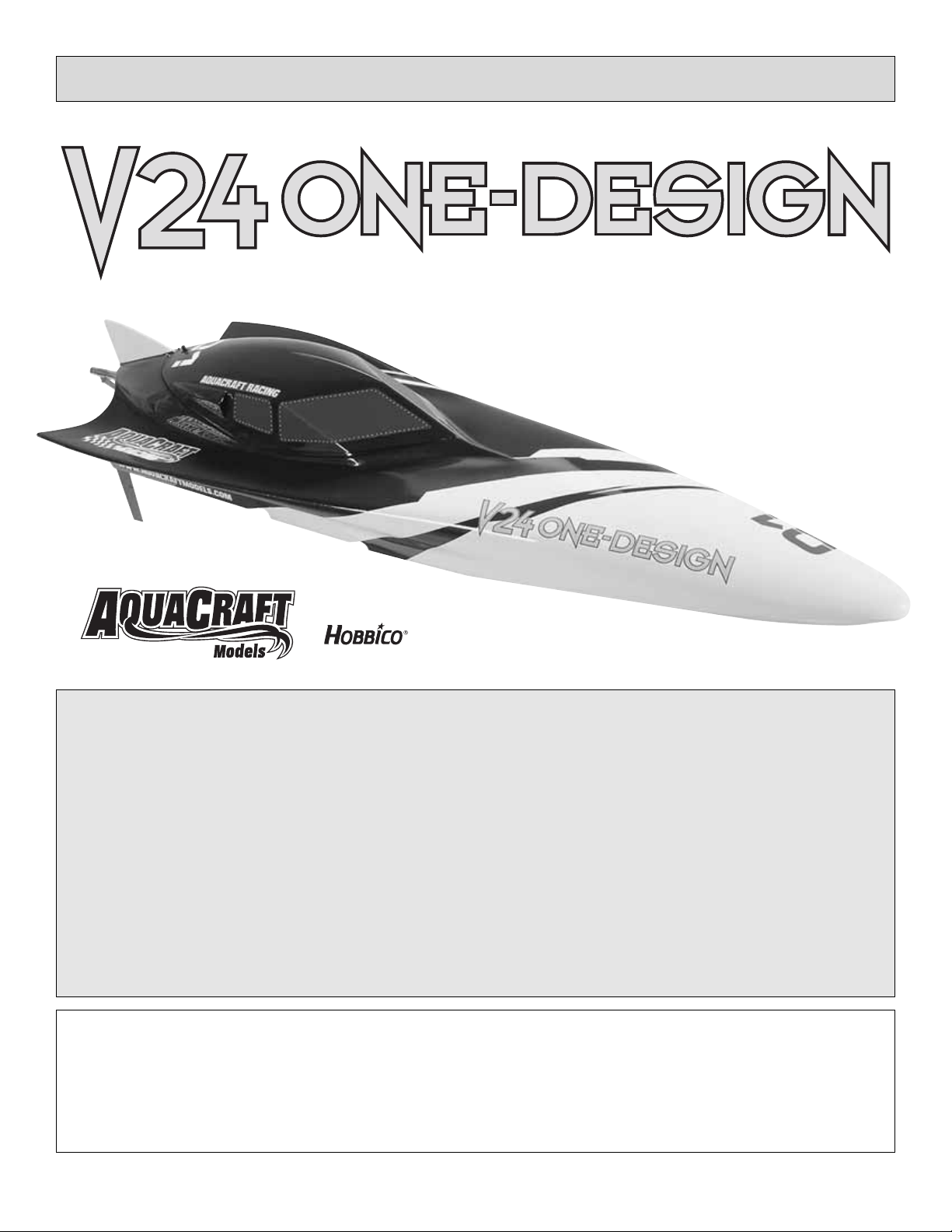
ASSEMBLE THE DISPLAY/WORK STAND
A display/work stand has been included with your V24 and
can be quickly assembled and disassembled.Simply join the
slots together as shown. If you prefer to keep the stand
assembled, you may glue the joints together with CA or
epoxy.This will also help to increase the stability of the stand.
Carefully place the V24 atop the display/work stand and
remove all remaining parts bags from the box. You may
wish to keep the box in order to more easily transport
and store your V24.
Decals have been provided for your V24. Simply cut
them out, peel and stick! See the photos on the box for
a decal placement example.
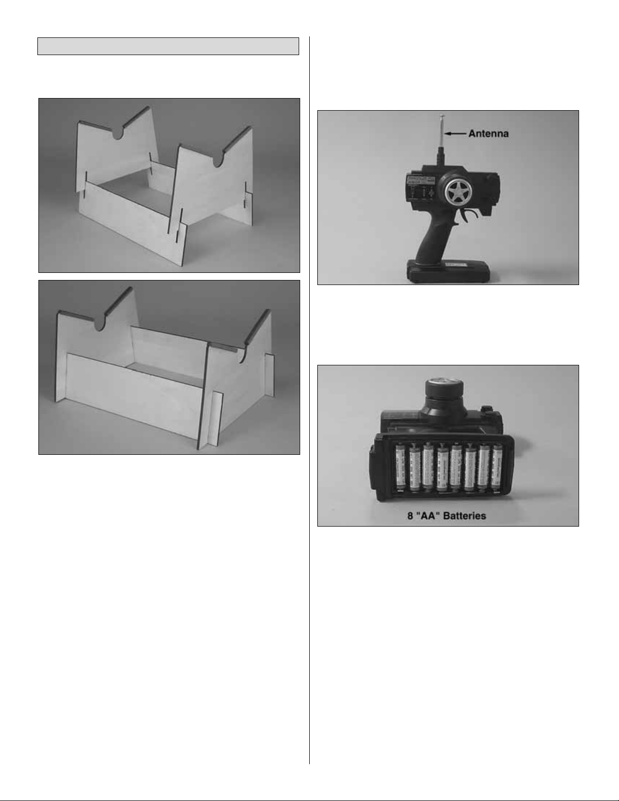
TRANSMITTER ASSEMBLY
Important Note: The transmitter is not water resistant
and should never come in contact with water.
❏ 1. Remove the transmitter antenna from the parts bag
and screw it into the top of the transmitter .To ensure that the
antenna is attached, lightly pull on the base of the antenna.
If it slides out, it is not installed properly.
❏ 2.Slide off the battery door on the bottom of the transmitter.
Install 8 fresh “AA” batteries into the bottom of the transmitter
in the configuration molded into the battery holder.Reinstall the
battery door onto the bottom of the transmitter.
❏ 3.Turn the transmitter “ON”using the switch on the front.
The battery level indicator should show two green and one
red light. If the level shows only the red light, the batteries
are low and need to be replaced.
V24 ONE-DESIGN FINAL ASSEMBLY
4
Page 5
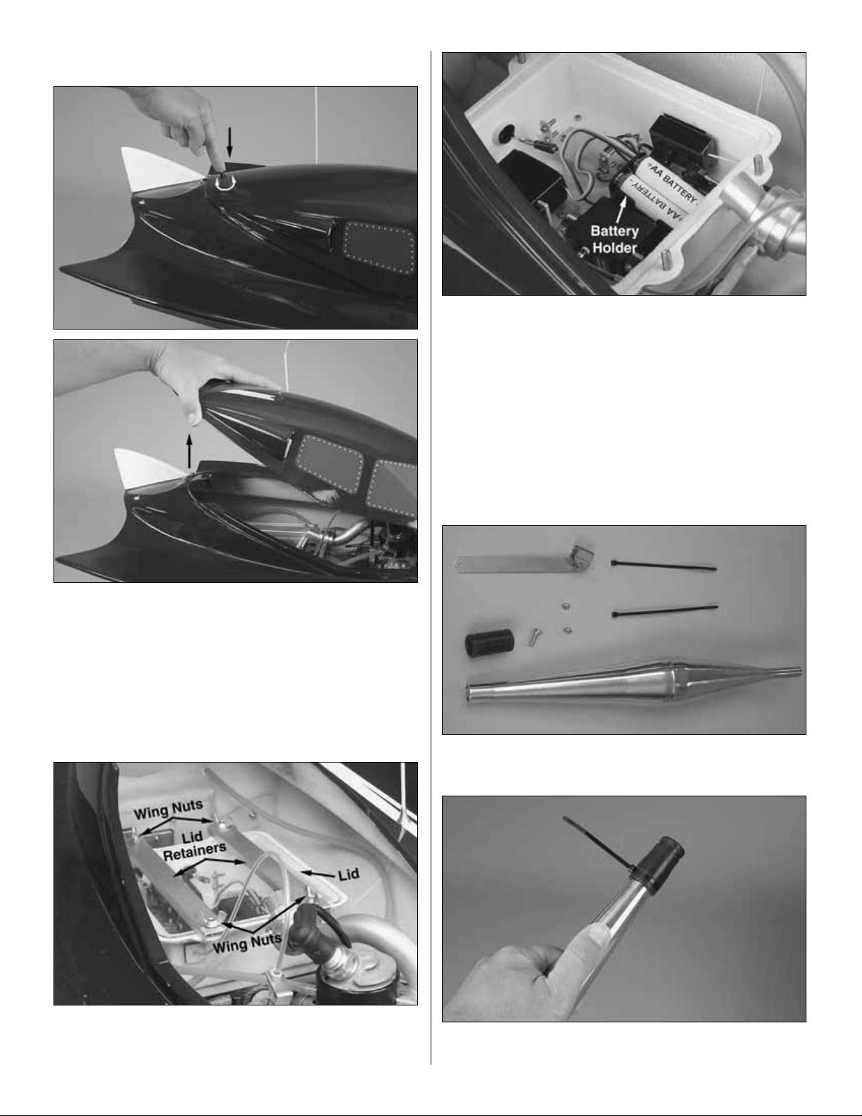
INSTALLATION OF RECEIVER BATTERIES
❏ 1. Locate the cowl lock button at the rear of the hatch.
Remove the hatch cover by depressing the button in a
twisting motion and then lifting as shown.
❏ 2. Remove the four (4) wing nuts and radio box lid
retainers as shown. This will allow you to remove the radio
box cover and access the receiver battery holder.
❏ 3. Place four (4) new “AA” batteries into the receiver
battery holder.Be sure to follow the polarity diagram molded
into the battery holder.
❏ 4. Replace the batter y holder inside the radio box. Make
sure that it will not interfere with any of the control linkages.
❏ 5. Replace the radio box cover and radio box lid
retainers. Secure them with the four (4) wing nuts.
INSTALLATION OF TUNED PIPE
❏ 1. Remove the tuned pipe, exhaust coupler, tuned pipe
brace, and (2) zip-ties from the accessory box.
❏ 2. Slide the exhaust coupler onto the large end of the
tuned pipe and secure it with one of the provided tie-straps.
5
Page 6

❏ 3. Slide the tuned pipe brace onto the small end of the
tuned pipe as shown.
❏ 4. Inser t the tuned pipe in through the exhaust outlet at
the rear of the boat until the exhaust coupler joins the tuned
pipe and exhaust manifold. Secure the exhaust coupler in
place with the remaining tie-strap as shown. Carefully cut
off the excess tie-strap end.
❏ 5. Place the tuned pipe brace onto the pipe brace mount
on the transom as shown and secure it with the 4mm nut.
❏ 6.Adjust the pipe so that it is not resting on the radio box
and insert the 4x15mm screw.Attach the 4mm nut.
INSTALLATION OF RUDDER
❏ 1.Locate the rudder from the accessory box.Remove the
3mm and 4mm nuts and the 4x15mm and 3x15mm screws.
❏ 2.Insert the rudder into the rudder control arm assembly as
shown. Replace the 4x15mm screw and 3x15mm screw and
secure them with the 4mm and 3mm nuts, respectively.
6
Page 7

❏ 3.Attach the water-cooling line to the rudder water pick-up
nipple as shown.
3-CHANNEL OPERATION
The V24 One-Design f eatures a variable strut unit that can be
adjusted manually or controlled by an optional third servo.
Installation of a third servo will require that you replace the
included radio gear with a 3-channel radio system.
As the boat is propelled forward and the speed increases,
the nose of the boat should lift out of the water slightly.
Adjusting the strut angle allows the propeller and engine to
work at maximum efficiency so the boat can reach faster
speeds (See Propeller Thrust Angle feature on page 12 and
3-Channel Operation feature on page 13).
CHECK THE RADIO SYSTEM:
• Standing behind the boat with both the transmitter and
receiver powered up , rotate the wheel to the left.The back
of the rudder should move towards the left. Move the
wheel to the right. The back of the rudder should move
towards the right. If this is not the case, simply move the
steering servo reverse switch to the other position.
• Squeeze the trigger on the transmitter; this should open the
throat of the carburetor. If this is not the case, simply move
the steering servo reverse switch to the other position.
The D/R knob located on the handle of the transmitter is the
steering rate adjustment. Turning the knob increases or
decreases the rudder movement.
SPARK PLUG
The recommended spark plug is a Champion RCJ-6Y. To
avoid improper operation or possib le engine damage, do not
use any other type of spark plugs. The plug gap should be
0.016" to 0.024" [0.4mm to 0.6mm]. If the plug gap is
incorrect, adjust it with a spark plug gapping tool, wash it
with gasoline and allow it to dry completely before you
reinstall the plug in the engine.
FUEL
Once the engine is broken in, use 40:1 (2.5% oil) fuel/oil
mix.Always use high quality oil intended for 2-cycle engines.
Prepare only the amount of gasoline needed.Aged gasoline
could damage the engine and cause it to overheat.
Use only low octane, alcohol-free gasoline. The carburetor
diaphragm will gradually deteriorate if you use gasoline with
alcohol.You will need to replace the diaphragm after about
80 hours of operation if you use gasoline with alcohol.
Fuel can go bad. Store your fuel out of the sunlight and in a
cool place. Bad fuel is one of the most difficult problems to
diagnose in engines. If you have tried everything you can
think of to remedy an engine that is not running correctly, try
using some fresh fuel.
OVERHEATING
One of the worst things you can do to your engine is
overheat it.The oil that lubricates the engine is carried in the
fuel. If your engine is set too lean, there will not be enough
oil in the engine to lubricate the internal parts. This will
cause premature wear in the engine and cause damage.
ENGINE ADJUSTMENTS
• Always make high and low-speed needle adjustments
while the engine is not running.
• Adjust the needle marked “H” for high-speed RPM. Adjust
the needle marked “L” for low-speed RPM.
NORMAL HIGH- AND LOW-SPEED NEEDLE SETTINGS:
It is not necessary to change the needle settings if the engine
runs smoothly. Normally only the “H” needle will need
adjustment from time to time and only by a small amount.
H: Open the needle 3/4 of a tur n from the closed position
(±1/4 of a turn in cold weather).
L: Open the needle 1-3/8 tur ns from the closed position
(±1/4 of a turn in cold weather).
Only adjust the high and low-speed needle within the
above range.
7
Page 8

IDLE ADJUSTMENT:
Important: Do not confuse the idle screw with the low-speed
needle “L”. The idle screw physically adjusts how much the
carburetor valve can close.The low-speed needle “L” adjusts
the gasoline to air mixture when the engine is running at low
RPM.If your engine appears to work correctly except that the
low RPM are not as low as you want them to be, then adjust
the idle screw. If your engine behaves erratically at low RPM,
then adjust the low-speed needle “L”. When adjusting, tur n
the screw about 1/8 of a turn each time.A dirty plug will make
it difficult to adjust the idle RPM. Follow the recommended
procedures if any of the following happens:
Problem:
• The engine hesitates when accelerated rapidly.
• The RPM increases at idling.
• The engine stops when the throttle is moved from high to low .
Solution:
Your low-speed needle “L” is too lean. Open it up
about 1/8 of a turn and try again.
Problem:
• The idle is not steady.
Solution:
Your low-speed needle “L” valve is too rich. Close
it 1/8 of a turn and try again.
HIGH-SPEED ADJUSTMENT:
The high-speed RPM and transition performance is adjusted
with the high-speed “H” needle valve. When adjusting, turn
the screw about 1/8 of a turn each time.The position of the
“H” needle will vary according to temperature and elevation.
If your engine is running smoothly then do not adjust this
needle valve.Follow the recommended procedures if any of
the following happens:
Problem:
• Engine stops at full throttle.
• Engine hesitates when accelerated rapidly.
• The engine will not come up to full RPM at full throttle.
Solution:
Your high-speed needle valve “H” is too lean.
Open it up 1/8 of a turn and try again.
Problem:
• Your engine does not reach full RPM.
• Carbon build-ups appear consistently on your spark plug.
Solution:
Your high-speed needle valve “H” is too rich.
Close it up 1/8 turn and try again.
To ensure long life and good performance from your Fuji BT-
24 Marine engine, you MUST break it in properly.To break-
in your BT-24 Marine, you need to run the engine for about
an hour with a fuel mixture that has a 25:1 (4% oil) fuel/oil
ratio. Patience is important here; the boat will run slowly
during the break-in process and the engine’s output power
will increase gradually over the first few tanks. Once the
engine is broken in and you begin running a 40:1 fuel/oil
mix, power will increase substantially.
• Do not adjust the high-speed needle on the carburetor to
break in the engine. If you do so, carbon will accumulate
in the spark plug and that will make ignition difficult.
• Do not run at full power for extended periods of time while
breaking in your engine.
• Make sure that the engine has adequate cooling.
Adjustments should be made on dry land with the boat
securely held in place.
BREAKING IN THE ENGINE
8
Page 9

There are several simple steps to starting the engine.It is a
good idea to have another person hold the boat in place
while you start the engine.
STARTING PROCEDURE:
IMPORTANT: The propeller will begin spinning as soon
as the engine starts! Be certain that the propeller is
unobstructed; failure to do so will damage the prop.
1. Carefully fill the fuel tank with the appropriate fuel/oil mix.
2.Turn on the transmitter and receiver (in that order).
3. Depress the priming bulb 2-3 times. This will begin the
flow of fuel into the carburetor.
4. NOTE: The engine was removed from the boat for
photographic purposes. You do not need to remove the
engine to open/close the choke. Close the choke on the
carburetor and pull the handle of the recoil starter until you
hear some initial firing sounds.DO NOT PULL THE RECOIL
HANDLE OUT ANY MORE THAN 25 INCHES; DOING SO
MAY DAMAGE THE RECOIL STARTER.
5. Quickly open the choke and pull the handle of the recoil
starter until the engine starts. THE PROPELLER WILL
BEGIN SPINNING AS SOON AS THE ENGINE STARTS!
6. After starting, let the engine idle for 15-20 seconds.Open
and close the throttle slowly until the engine runs smoothly
at idle and at full throttle. Acceleration should also be
smooth. DO NOT RUN THE ENGINE FOR EXTENDED
PERIODS OF TIME WITHOUT SUFFICIENT COOLING!
7.If your engine does not start, repeat the starting procedure.
8.With the engine started, put the hatch cover back in place.
Press the cowl lock and twist to secure it. BE CAREFUL
NOT T O TOUCH THE SPINNING PROP!
IMPORTANT: Unlike full scale boats, model boats race in a
clockwise circuit and it is the nature of model race boats to
make right turns more easily than left turns. If you absolutely
have to turn left, do so at very slow speed and allow yourself
plenty of room.
ST ARTING THE ENGINE
AND LAUNCH PROCEDURE
9
Page 10

9. Gently place the boat in water that is at least 8" deep and
free of obstacles (weeds, rocks, stic ks, duc ks , muskrats , etc.).
Be sure to stay clear of the spinning prop during the launch.
10. Slowly advance the throttle and note if the boat has a
tendency to turn right or left. Adjust the steering trim knob on
your transmitter until the boat runs in a straight line when the
steering wheel is at neutral.
11. When finished running, use the kill switch to stop the
engine and turn off the receiver and transmitter (in that order).
If the V24 pulls sharply to the right when accelerating, add
weight to the portside near the radio box. You will need to
experiment in order to determine most effective placement.
If the engine fails to start, refer to the TR OUBLESHOO TING
CHART on page 8.
HOW TO STOP YOUR ENGINE
For safety purposes, your V24 comes equipped with a kill
switch that can completely disable the engine until you are
ready to start it.
PLEASE READ these valuable running tips as well as the
“Safety Precautions” at the beginning of this manual
BEFORE Running the V-24 to ensure a successful and
safe run.
• NEVER attempt to swim after a stalled or capsized boat!
Wait patiently for the wind currents to return the boat to
shore or use a tennis ball attached to the end of a fishing
rod to retrieve a stalled or capsized boat.
• NEVER threaten wildlife with any R/C vehicle! This is the
quickest wa y to get R/C boating banned from y our favorite
local pond.
• It is dangerous to operate any R/C vehicle at any time that
there is not sufficient light.
• R/C models produce vibrations which
will
cause screws,
nuts, bolts, etc, on y our model to become loose over time.
It is important to make sure that all hardware is
secure before operating your model.
• Before running your V24, it is a good idea to check the
water-cooling system to make sure all tubes are
properly connected and unblocked.
• Do not attempt to stop the engine by throwing anything
into the path of the propeller or by grabbing the driveshaft.
• The edges of the propeller are very sharp and can cut
you very badly if you are not careful. At no time should
you ever attempt to stop the prop with your hand. In the
event that weeds become entangled in the propeller, stop
the engine before attempting to remove them.
• IMPORTANT: If, for whatever reason your boat takes on a
large amount of water causing the radio equipment to get
wet, you must do the following immediately: Remove the
battery pack and radio equipment from the boat.Allow the
components to air dry completely before reassembling.
Reinstall the components and check for proper operation
before running the boat again.
• If your engine should ever become submerged, remove
the spark plug and pull the handle of the recoil starter
several times until all water has been expelled from the
engine. Once you are positive that all water has been
removed from the engine and the spark plug is completely
dry, reinstall the plug and perform the starting procedure.
This may take several attempts.
• Always use a balanced prop. An unbalanced prop will
cause high levels of vibration that may be harmful to your
driveshaft and engine.
• Be sure to keep your driveshaft well lubricated. Failure to
do so may cause vibrations that can be harmful to the
engine. Re-lubricate your driveshaft frequently (See
Driveshaft Maintenance
on page 11).
• Do not use silicone fuel line because gasoline will ruin it.
Use vinyl or neoprene rubber fuel line instead.
• Use an in-line fuel filter intended for use with gasoline
engines. Metal filters intended for glow engines are too
coarse and will not screen out finer particles.
• CAUTION!The engine will be hot! Allow it to cool for a f ew
minutes before restarting.
• Total r un time of the V24 is approximately 25-35 minutes
(assuming you begin with a full tank of fuel). When you
notice an increase in power, it means the fuel tank is
nearly empty and it’s time to head for shore. As soon as
the boat reaches shore, stop the engine by pushing
forward on the kill switch. Open the hatch and turn off the
receiver and transmitter (in that order).
10
Page 11

• CAUTION: Windy conditions cause rough water that will
affect the performance of your V24 and increase the
chances of capsizing.
• Your V24 may take on water when running in rough
conditions and when making tight turns. Keep a roll of
paper towels handy and dry out the hull interior after every
run. Check for leaks if you notice excessive amounts of
water in the hull.
THE WAITING GAME
If your V24 should happen to stall, water currents will slowly
carry it to shore. The bad news is that the boat could be
carried to the opposite shore. When surveying areas to run
your V24, keep v ariables in mind such as wind direction, size
of the lake, etc. It is not advisable to run R/C boats on any
free-flowing bodies of water such as creeks or rivers.
HELPFUL TIP:
Use a fishing rod with at least 15lb line and
a tennis ball tied to the end to retrieve a stalled boat.
BASIC MAINTENANCE
When you are through operating your boat for the day, be
sure to perform these basic maintenance procedures. This
will prolong the life of the V24 and help to ensure troub le-free
running.Make sure that the engine kill switch is set to the
“OFF” position before performing any maintenance.
• Remove the hatch cover.
• Open the radio box.
• Soak up any excess water with a paper towel.
• Remove the driveshaft and wipe aw ay as much grease as
you can.Spray the driveshaft down with WD-40 and place
it in a plastic bag until you are ready to operate the boat
again (See Driveshaft Maintenance feature below).
• Wipe down the entire boat with spray-on glass cleaner
and a paper towel.
DRIVESHAFT MAINTENANCE
The flexible driveshaft is the most abused component of a
gas boat. IT IS CRUCIAL that you remove the drive shaft
and lubricate it with Speed Grease Driveline Cable Lubricant
(HCAB3000) or some type of heavy-duty marine grade
cable grease at the beginning of each daily session and
again every couple of tanks. This exercise will require a
1.5mm hex driver.Make sure that the engine kill switch is
set to the “OFF” position during this procedure.
1. Usa a 1.5mm hex key to loosen the 3x3mm set screw
located on the strut assembly, and slide the retainer pin out
as shown.
2.Gently pull the driveshaft out and wipe off any excess grease
with a clean rag.
3.Apply Speed Grease Driveline Cable Lubricant (HCAB3000)
or heavy-duty marine grade cable grease to the driveshaft and
reinsert it into the stuffing box.Slowly rotate the driveshaft while
gently pushing it back into place.
4. Slide the retainer pin back in place and retighten the
3x3mm set screw on the strut assembly, making sure that
the set screw rests on the flat spot of the retainer pin.
MAINT AINING THE V24
11
Page 12
ENGINE MAINTENANCE:
Ways To Ensure A Long Life For Your Engine.
• Keep your engine clean. Dirt will act as insulation on an
engine and prevent it from shedding heat easily.
• Do not over-lean your engine.
• Do not run your engine without a propeller.
• Do not overheat the engine.This goes along with keeping
it clean and not over-leaning the engine.
• Avoid using old fuel in the engine. Always run all of the
fuel out of the engine. After r unning for the day, use afterrun oil and work it into the engine by pulling the pullstarter 2-3 times.
• Store your engine someplace where it will not be
subjected to extreme temperature changes.
• Before transporting your model, remove all of the gasoline
from the tank and lines.
• If you are not planning to run your engine for more than a
month, drain the fuel tank and remove any fuel from inside
the carburetor. Do this by running the engine at idle until it
quits by running out of fuel. Keeping gasoline inside the
carburetor over an e xtended period of time will damage the
diaphragm valve and clog passages inside the carburetor.
RADIO BOX MAINTENANCE
• Line the forward interior of the radio box with paper towel
prior to running to absorb moisture.
• Place the receiver in a rubber balloon to provide added
protection from moisture.
• Use a water-resistant tape to seal the radio box lid to the
radio box.
• When finished running, open the radio box and soak up any
moisture that may hav e made its wa y into the compartment.
• Should moisture gain access to the radio box, all
connections should be dried thoroughly. Hobbico “Duster”
Compressed Air (HCAR5500) will provide a blast of air
capable of blowing moisture out of connectors.
HULL MAINTENANCE
• After running, the exterior of the hull should be cleaned.
Common household cleaners can be utilized for cleaning.
Areas exposed to fuel/engine exhaust residue should be
thoroughly cleaned. Agents in the fuel/exhaust residue can
attack the finish if allowed to remain on the surf ace ov er time.
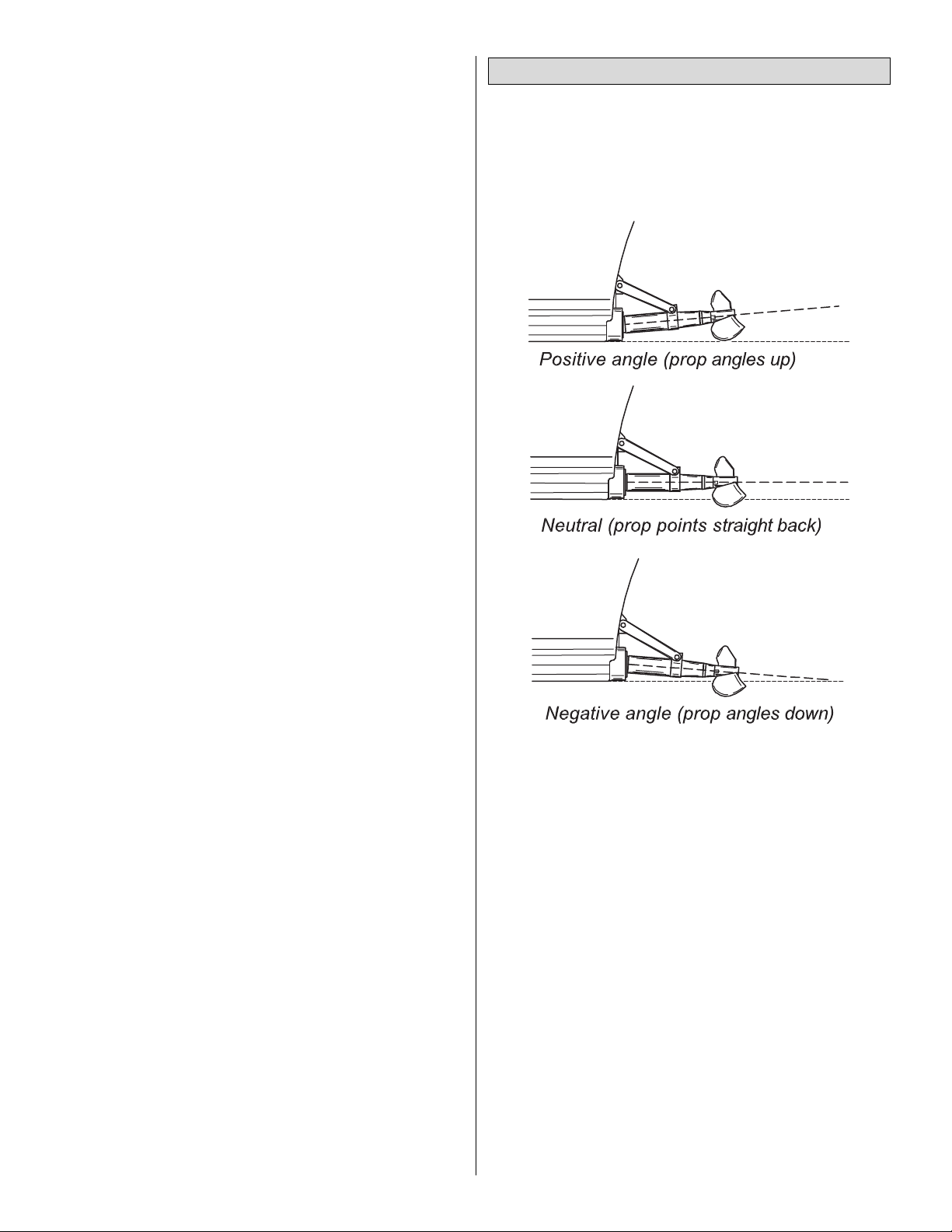
As an initial starting point, try running the V24 with a neutral
propeller thrust angle (See Figures 1-3 above).This can be
checked by placing a straight edge along the bottom of the
hull and checking its relation to the prop shaft.
Neutral Propeller Thrust: Provides thrust without letting the
thrust affect the ride attitude of the hull (the bow’s tendency
to ride up or down).
Positive Propeller Thrust: Causes a “bow upward” ride
attitude.A “bow upward”ride attitude will increase speed but
as it does, handling becomes more sensitive.
Negative Propeller Thrust: Causes the hull to r ide “stuck
down” (flat on the water). This reduces speed and may
cause the boat to submerge in a turn.
Be sure to retighten all the screws upon establishing the
desired thrust angle.
PROPELLER THRUST ANGLE INFORMATION
12
Page 13
The optional third channel will allow you to adjust the strut
and prop angle while the boat is in motion. This option is
used mainly by serious racers who need to fine-tune their
struts during a race. Once the proper thrust angle is
achieved manually by the average modeler, it is unlikely that
it would be used very often. In other words, a 3-channel
radio is not essential to have fun with this boat!
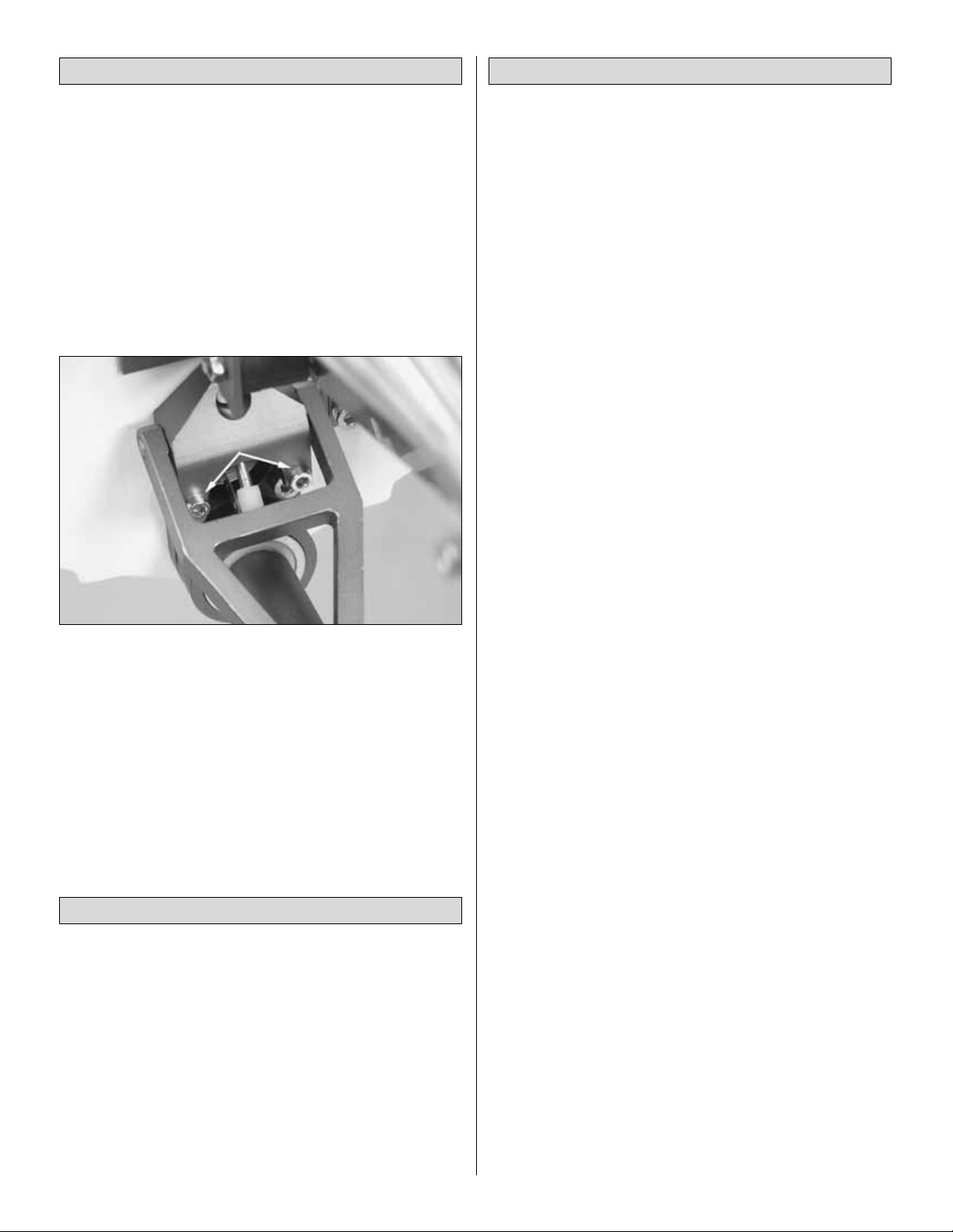
The procedure requires a 3-channel radio system (of
course!), an additional servo (preferably high torque), and
removing the two 3x10mm hex head screws that keep the
strut stationery (See photo below).
Once the two 3x10mm hex head screws ha ve been remo ved,
the strut assembly linkage is able to move freely. Simply
attach the strut linkage to the arm of your third servo and you
are ready for some serious racing!
IMPORT ANT SAFETY TIPS: It is recommended that you use
a 5-cell rechargeable receiver battery pack if you decide to
use the third channel option. However, since gasoline fumes
can build up inside the hull, you should NEVER attempt to
charge a battery pack while it is in the boat.
To avoid damage to the engine and flexible driveshaft,
balancing metal propellers is highly recommended. Balancing
a propeller requires the use of a balancing device such as the
Top Flite®Pow er Point®balancer (TOPQ5700), metal files, and
400 grit wet/dry sandpaper. The front, rounded side of the
propeller is the surface from which material is removed.Follow
the curvature of the propeller surface. Continue checking the
propeller on the balancer until the propeller is balanced. 400
grit wet/dry sandpaper will provide a smooth finish.
NOTE:While polishing a propeller improves its appearance,
it does not improve performance.
Although it is very enjoyable to run the V24 by yourself, the
real fun and excitement of R/C boating is experienced when
you get involved in racing. Racing against other boats is
much different than running your boat alone. The following
suggestions will hopefully provide helpful strategies when
racing a model boat.
A good set-up for running alone may not be the best for
racing. Race water conditions create challenges different
from running alone and water conditions constantly change
during a race. Five or six boats racing against one another
will create rough water on the race course. To compete
successfully, it may be necessary to “tighten” the ride
characteristics. This can be accomplished by lowering the
depth of the propeller or adding additional weight to the front
of the boat.
Wakes caused by other boats can upset the balance and
ride characteristics of even a well trimmed model boat.
When running down the straight-aways, don’t follow in
another boat’s wake.Wakes generated by other boats while
entering and negotiating a corner are especially dangerous.
Cutting across a wake when entering a corner can cause
the boat to “hook” (spin to the inside) and stall.
Racing other boats through a corner may be a competitor’s
greatest challenge, especially the first corner after the start
of a race.The boat entering the cor ner first has the task of
holding its position (often called “holding your lane”) through
the corner. The following boats must then attempt to hold
their lanes, too.Changing lanes and crossing a wake to gain
a position in a turn can result in “hooking” and elimination
from that race. Executing a good start in the inside lane is
one key to successful racing.
Avoid beating yourself.In any type of racing, there are some
situations you can control and other situations that you
cannot control. The ability to set the needle-valve on the
engine so it runs the entire race without stopping, checking
the linkages, fasteners, fuel tubing, amount of fuel, glow
plug, and radio system are conditions/situations that can be
dealt with prior to the start of a race. During the race, making
a good start and driving defensively are controllable actions.
By focusing on tasks and actions that can be controlled,
successful racing outcomes can be achieved.
RACING
BALANCE THE PROPELLER
3-CHANNEL OPERATION
13
Page 14

NATIONAL MODEL BOATING ORGANIZATIONS
There are three national model boating organizations in the
United States and Canada:
APBA or American Power Boat Association (RC Boat Category)
www.apba-rcboating.com
IMPBA or International Model Power Boat Association
www.impba.net
NAMBA or North American Model Boat Association
www.namba.com
Each of these organizations has its own rules governing
model boat racing, sanctioned events and recognized
records. Organized model boat racing is offered at both
regional and national levels .Location of clubs, race dates and
locations, membership applications, and other information
can be obtained through their respective websites.
All three offer both stock and modified engine classes for hulls
like the V24. Participation by those new to the hobby of model
boating is possible through club events.
Here are some more good sources of information regarding
all aspects of model boat operation:
International Waters Jim’s RC Boat Dock
www.intlwaters.com www.jrcbd.com
Of course, racing does not have to be an organized and
sanctioned competition to be fun. Small informal races can be
very exciting without the stress that comes with formal events.
SUGGESTIONS FOR SETTING UP
A SIMPLE RACECOURSE
• Make 2 to 4 simple and inexpensive “marker buoys”with
empty milk jugs, string, and heavy objects for anchors,
similar to the above sketch.
•For “drag racing”place the buoys similar to the abov e sketch.
• For “oval racing” place the buoys similar to the above
sketch. NOTE: The above patterns are not based on
official standards. You may set up racecourses any way
you desire, using your imagination to make the races
more interesting. Usually, smaller courses will provide
more action and excitement.
• The length of the races can be determined by a set number
of laps around the buoys (for example, the first boat to
complete 5 laps is the winner); or by time (for example,
whoever is leading at the end of two min utes is the winner).
GOOD LUCK AND GREAT BOATING!
14
GALLON-SIZE
PLASTIC MILK JUG
NYLON STRING
(ENOUGH TO REACH BOTTOM)
BOLT, ROCK OR HEAVY
OBJECT FOR ANCHOR
Page 15

To order replacement par ts for the AquaCraft V24, use the
order numbers from the lists below. Replacement par ts are
available only as listed and can be purchased from hobby
shops or through mail order/ Internet order firms. Hardware
items (screws, nuts, bolts) are also available from these
outlets.If you need assistance locating a dealer to purchase
parts, visit www.hobbico.com and click on “Where to buy”. If
this kit is missing parts, contact Hobbico Product Support.
ORDER # ITEM
HCAB6464 Fiberglass Cowl w/cowl lock
HCAB6902 Gas Boat Fuel Tank, 24oz.
HCAB7859 Flex Cable w/prop shaft, 1/4"
HCAB7862 Stuffing Tube
HCAB7863 Engine Flex Cable Collet
HCAG5101 Exhaust Header
HCAG5911 Tuned Pipe, 23cc - 30cc Gas
HCAB8200 Tuned Pipe Suppor t Brace
HCAB6502 Gas Engine Isolation Mount, 23-30cc
HCAB8605 Radio Box, Fiberglass w/Lid
HCAB9011 Servo Linkages w/connects
HCAB7865 Drive Dog w/screw,washer, 1/4"
HCAZ1003 Instr uction Manual
HCAB6314 Decal Sheet
HCAB7866 On-board Adjustable Surface Drive, 1/4"
HCAB7864 Prop Shaft for Adjustable Surface Drive
HCAG4736 Gas Exhaust Coupler w/tiewraps
HCAB7008 Push Button Cowl Locks (2)
HCAB8606 Radio Box Waterproof Tape
HCAG6010 Gas Engine Toggle Kill Switch
HCAB8708 Machined Aluminum Rudder, Blue alum
HCAB8709 Rudder Support Assembly, Blue alum
HCAB8710 Aluminum Rudder Control Arm
HCAB9260 Water Line nipples, std
HCAB9043 Adj.Trim Tabs w/water pick up
HCAB7761 Propeller, Balanced/Sharp 65mm Stainless
HCAG5110 Water Cool Header Jacket
HCAG5111 Water Cool Exhaust Flange for Fuji engine
HCAB6700 Water-proof Switch Boot w/ON-OFF Plate
HCAB6701 Radio Box Water Seal Boot (2)
HCAB7008 Push-button Cowl Locks (2)
HCAB8604 Antenna Tube w/ Cap
HCAB6702 Receiver Water-Proof Balloon (2)
HCAB8603 Radio Box Foam
HCAB8606 Radio Box Water-Proof Tape
HCAB3000 Speed Grease Driveline Cable Lube
Crankcase
Key # Part # Description
16......FJIG3830..................................Crankcase Assembly
17......FJIG6300........................................Oil Seal TB12227
18......FJIG3080 .................................Ball Bearing 6001 C3
19......FJIG3920......................................Crankcase Gasket
20*.....FJIG7310.................................Gear Shaft Shim 0.10
20*.....FJIG7311.................................Gear Shaft Shim 0.15
20*.....FJIG7312.................................Gear Shaft Shim 0.20
20*.....FJIG7313.................................Gear Shaft Shim 0.30
21......FJIG5315 ................................Ignition Coil Complete
24......FJIG0020.................................Magneto Rotor 60mm
25......FJIG0020.......................................................Adapter
28......FJIG8220...............................Hex Hole Bolt 4x18WS
32......FJIG8290 ..................................Hex Hole Bolt 5x18S
Engine
Key # Part # Description
1........FJIG5480..........................................Insulator Gasket
2........FJIG5515 ...............................................Insulator Set
3........FJIG8305 .................................Hex Hole Bolt 5x22/S
4........FJIG8645 ....................................Small Washer 5mm
5........FJIG3110 ......................................Carburetor Gasket
6........FJIG8340.....................................Hex Hole Bolt 5x50
7........FJIG8605 ..............................................Washer 5mm
8........FJIG8645 ....................................Small Washer 5mm
9........FJIG3230............................................Carburetor Set
ORDERING REPLACEMENT PARTS
15
Page 16

Recoil Starter
Key # Part # Description
0........FJIG7130.......................Recoil Start Body Assembly
1........FJIG7134 ............................................Starter Handle
2........FJIG7131.......................Recoil Star t Body Complete
3........FJIG7132................................................Recoil Rope
4........FJIG7133 ..............................................Recoil Spr ing
6........FJIG7135................................................Spring Case
8........FJIG7136...............................................Sarter Pulley
9........FJIG8606...............................Special Washer 5.2x15
10......FJIG7164 ...................................Tapping Screw 5x14
15......FJIG7137................................................Star ter Base
16......FJIG7162 ................................Tapping Screw 4.5x14
17......FJIG8190...............................Hex Hole Bolt 4x12WS
20......FJIG7138 .............................Starter Pulley Assembly
Cylinder/Piston/Crankshaft
Key # Part # Description
1........FJIG7470 ....................................Spark Plug RCJ-6Y
2........FJIG4441................................................Cylinder Set
3........FJIG8290..........................................Hex Bolt 5x18/S
4........FJIG4291..........................................Cylinder Gasket
5........FJIG6635 .................................................Piston Ring
6........FJIG6361 ...................................................Piston Set
7........FJIG6419 ...................................................Piston Pin
8........FJIG6509 ........................................Piston Pin Circlip
9........FJIG8719...............................Water Jacket Complete
10......FJIG7160...................................................Screw 3x8
11......FJIG4019..................................Crankshaft Complete
12......FJIG6149..............................Needle Bear ing 1.4x8.5
13......FJIG7660..............................................Woodruff Key
14......FJIG6260 ........................................................O-Ring
15......FJIG7500 ..........................Spark Plug Cap Assembly
Carburetor
Key # Part # Description
2........FJIG5460 ................................................Inlet Screen
3........FJIG6930.................................................Pump Body
4........FJIG7170 ...................................................Set Screw
5........FJIG7060..............................................Pump Gasket
6........FJIG7020 ........................................Pump Diaphragm
7........FJIG4610......................................Diaphragm Gasket
8........FJIG5760 ........................Metering Diaphragm Comp
9........FJIG3020..........................................Air Purge Comp
10......FJIG4520........................................Diaphragm Cover
11......FJIG6210 ..............................................Pr iming Body
12......FJIG8525................................................Valve Spring
13......FJIG6240...............................................Needle Valv e
15......FJIG7540.................................................Valve Hinge
16......FJIG5130...................................Hinge Pin Set Screw
17......FJIG5100....................................................Hinge Pin
18......FJIG5220........................................Idle Adjust Screw
19......FJIG5285 .......................................Idle Adjust Spring
27......FJIG7161 ...................................................Set Screw
28......FJIG5070..............................High/Low Adjust Spring
29......FJIG5590.......................................Low Adjust Screw
30......FJIG5040 ......................................High Adjust Spr ing
31......FJIG4940 ......................................High Adjust Screw
 Loading...