


AquaCraft Miss Vegas Deuce User Manual
™
WARNING:
• Never attempt to swim after a stalled R/C boat.
• Never operate your R/C boat while standing in the water.
• Never operate your R/C boat in the presence of swimmers.
• Always use a Personal Flotation Device (PFD) when boarding and operating your retrieval craft, i.e. Jon
boat or duck boat. NOTE: Because of the sharp running hardware included with this R/C boat, we do not
recommend a rubber blow up raft.
• R/C boat running hardware is very sharp. Be very careful when working on and around the metal parts.
• While the motor is running pay close attention to the propeller. Do not come in contact with the propeller at
any time the engine is running or serious injury will result.
• AquaCraft products are to be used by ages 14 and over.
CAUTION: The performance of this R/C boat is not for the faint of heart! Out of the box speeds
can reach 40 MPH. Your full attention must be maintained while operating this product.
aquacraftmodels.com
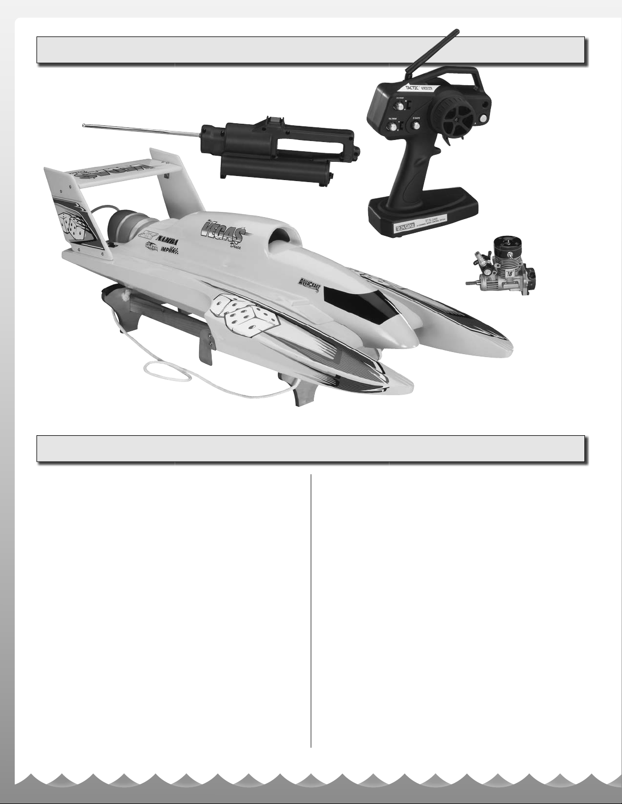
ITEMS INCLUDED
WARRANTY
AquaCraft will warrant your Miss Vegas Deuce hull for 90 days
after the purchase from defects in materials or workmanship of
original manufacture. AquaCraft, at their option, will repair or
replace at no charge, the incorrectly made part. This warranty
does not cover damage caused by crash, abuse, misuse,
alteration or accident. To return your boat for repairs you need
to provide proof of purchase. Your store receipt or product
invoice will suffi ce. IN NO EVENT SHALL THE PURCHASER
BE ENTITLED TO ANY INCIDENTAL, SPECIAL, INDIRECT
OR CONSEQUENTIAL DAMAGES, WHETHER RESULTING
FROM THE USE, MISUSE OR INABILITY TO USE THE
PRODUCT OR FROM DEFECTS IN THE PRODUCT. This
warranty gives you specifi c legal rights and you may also have
other rights, which vary from state to state. (Outside USA and
Canada, contact local importer for warranty information.)
Hobby Services
3002 N. Apollo Drive, Suite 1
Champaign, Illinois 61822
Attn: Service Department
Phone: (217) 398-0007
9:00 am - 5:00 pm Central Time M-F
E-mail: hobbyservices@hobbico.com
STANDARD REPAIR SERVICE
After the 90-day warranty has run out, you can still have your
Miss Vegas Deuce repaired for a service fee by the experts
at AquaCraft.To speed up the repair process, please follow
these four simple steps:
Important Note: For standard repair service you must specify
whether you wish the charges to be billed COD or if you wish
to be notifi ed of the charges so you can send a check.
1. Please return the ENTIRE system, boat and radio.
2. Make sure batteries are removed from the transmitter.
3. Send written instructions which include a list of all items
returned, a THOROUGH explanation of the problem or
problems of the service needed. Be sure to include your
return address and daytime phone number. If you have
access to e-mail please provide us with your e-mail
address to help speed communication.
4. Send to the address at left.
2
INTRODUCTION
Thank you for purchasing the AquaCraft™ Miss Vegas
Deuce! We want the time you spend with your new R/C boat
to be fun and successful, so please fully read the manual. If
for any reason you think this R/C model is not for you, return
it to your local hobby dealer immediately. Your hobby dealer
cannot accept returns on any model after final assembly or
after your boat has been operated.
™
SAFETY PRECAUTIONS
ITEMS NEEDED TO COMPLETE
YOUR MISS VEGAS DEUCE
• HCAP2520 Hot Shot™ 2 Glow starter
• ODOP3130 30% Nitromethane model boat fuel (1 quart)
• DTXP0125 Kwik-Pit
• 8 “AA” batteries (FUGP7316 – 16 pack)
™
250 fuel bottle
OPTIONAL ITEMS
It is a good idea to assemble a useful collection of tools and
accessories to bring along anytime you head out to the pond.
Here are some items you will want to keep handy.
• Never, ever, attempt to swim after a stalled R/C boat.
Do not get in the water for any reason to retrieve your
boat. To aid you in retrieving a stalled R/C boat, set up a
fi shing reel with a tennis ball tied to the end of the line.
Or better yet, get yourself a small boat so you can row
out and pick up your R/C boat. Remember to use a PFD
any time you enter your retrieval craft.
• AquaCraft products are to be used by ages 14 and over.
• Do not touch the propeller anytime the motor is spinning.
Pay equally close attention to items such as loose clothing,
shirtsleeves, ties, scarves, long hair or anything that may
become entangled in the spinning prop. If your fingers,
hands, etc. come in contact with the spinning propeller, you
may be severely injured.
• The speed and mass of this boat can inflict property damage
and severe personal injury if a collision occurs. Never run this
boat in the presence of swimmers or where the possibility of
collision with people or property exists.
• This boat is controlled by radio signals, which are susceptible
to possible interference.
• If your Miss Vegas Deuce should happen to stall, water
currents will slowly carry it to shore. The bad news is that
the boat could be carried to the opposite shore. When
surveying areas to run your model, keep variables in
mind such as wind direction, size of the lake, etc. It is not
advisable to run R/C boats on any free-flowing bodies of
water such as creeks or rivers.
• #2 Phillips screwdriver (HCAR1024)
• Hobbico
• Metric and standard hex drivers
• Adjustable wrench
• Needle-nose pliers (HCAR0625)
• After Run engine oil (HCAP3000)
• Glow plugs
• Fuel tubing (GPMQ4131)
• Hook & loop material (GPMQ4480)
• Hobby knife (HCAR0109)
• AquaCraft Speed Grease
Marine-grade grease (for lubricating the fl exible drive cable)
• Zip-ties
• Extra “AA” batteries
• Thread-locking compound
• CA glue and debonder
BELT STARTING SYSTEM
If you would like to update your Miss Vegas Deuce Super
Tigre® engine to belt start, here is a list of the components
you will need:
• SUPG2052 – SuperTigre® Standard Back Plate .18 Marine
• AQUB9531 – AquaCraft™ 17" Starting Belt
• HCAP3200 – Hobbico TorqMaster™ 90 Deluxe 12V Starter
• HCAP0800 – Hobbico TorqMaster LC 12V 7Amp Battery
®
heavy-duty diagonal cutter 7" (HCAR0627)
™
cable lubricant (AQUB9500) or
MANUAL SPECIFICATION AND
DESCRIPTION CHANGES
All pictures, descriptions, and specifi cations found in this
instruction manual are subject to change without notice.
AquaCraft maintains no responsibility for inadvertent errors
in this manual.
OTHER USEFUL ITEMS
TO HAVE ON HAND
• Paper towels
• Spray-on glass cleaner
• Sunglasses
• Sun block
• Waders or rubber boots
• Cooler with plenty of ice and soda
• Folding table
• Lawn chairs
• First-aid kit
• EZ-up or canopy for shelter
3
FINAL ASSEMBLY
Carefully remove your Miss Vegas Deuce from the box and
place it atop the pre-built boat stand. Remove all remaining
components from the box. You may wish to keep the
box in order to more easily transport and store your
Miss Vegas Deuce.
Decals have been provided for your Miss Vegas Deuce.
Simply cut them out, peel, and stick! See the photos on
the box for recommended decal placement.
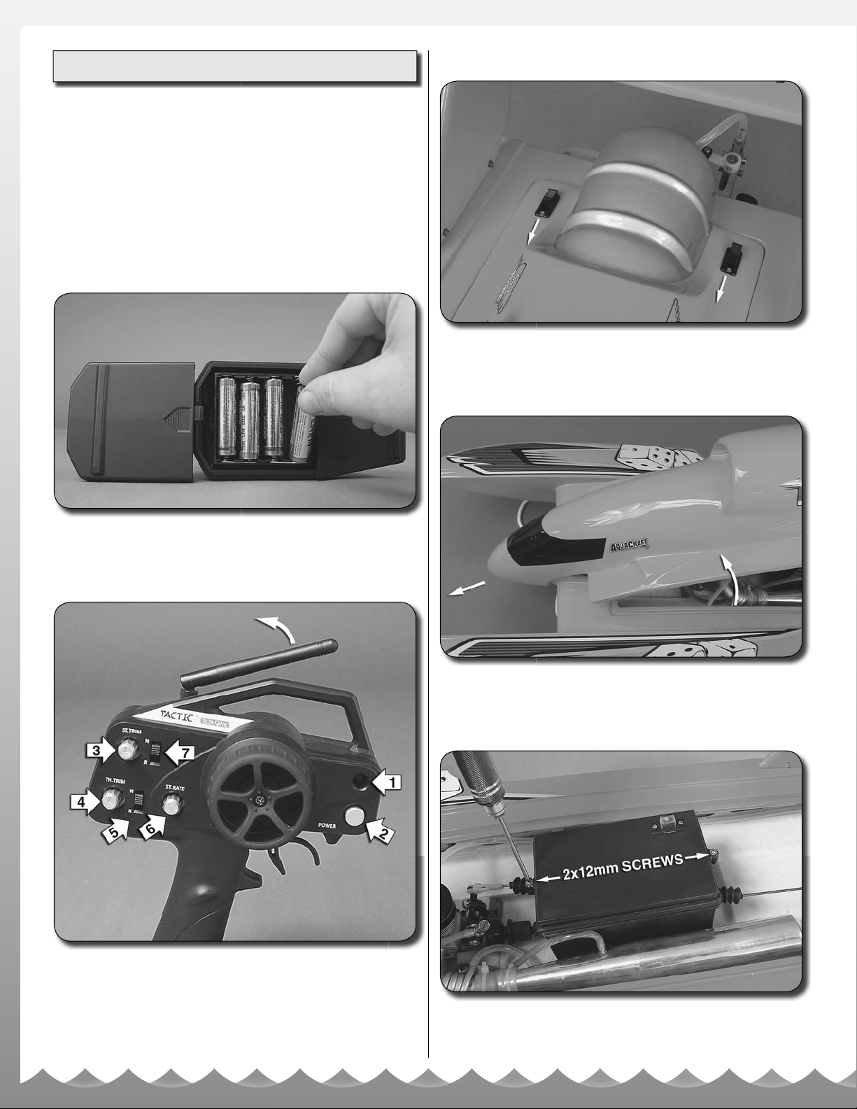
TRANSMITTER ASSEMBLY
INSTALLATION OF RECEIVER BATTERIES
1. Locate the cowl locks on the rear hatch cover and slide
them forward.
1. Slide off the battery door on the bottom of the transmitter.
Install four fresh “AA” batteries into the bottom of the transmitter
in the confi guration molded into the battery holder. Re-install
the battery door onto the bottom of the transmitter.
2. Lift the rear of the canopy and slide it forward to access
the interior of the hull.
1. Power Light
2. On/Off Switch
3. Steering Trim
4. Throttle Trim
5. Throttle Reverse
6. Steering Rate
7. Steering Reverse
2. Turn the transmitter on using the switch on the front. The
red LED should light up. If the LED does not light up, turn the
transmitter off and check to make sure that the batteries are
installed properly. If you see a fl ashing LED, the batteries are
low and need to be replaced.
4
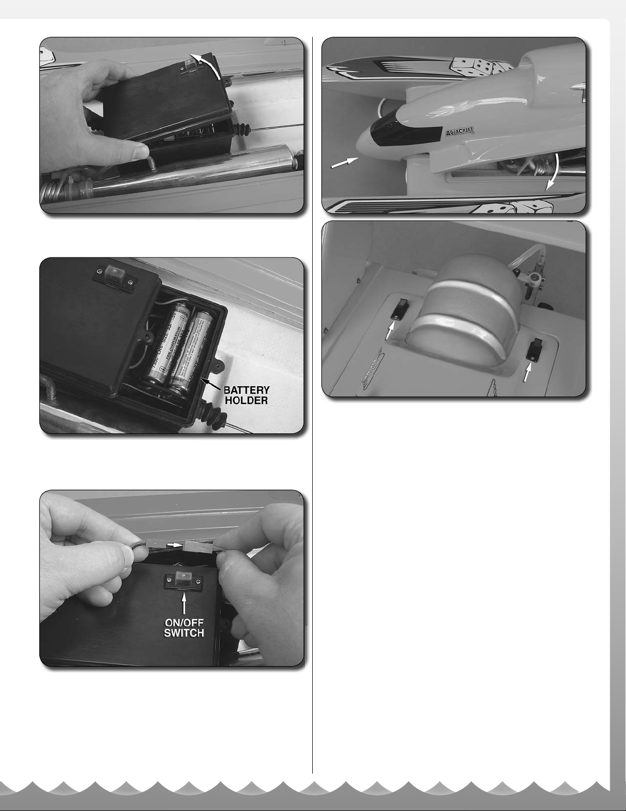
3. Remove the two 2 x 12mm screws that secure the radio
box lid and gently lift the lid from the battery box.
4. Install four fresh “AA” batteries in the battery holder. Be
sure to follow the polarity confi guration molded into the
battery holder.
7. Replace the canopy by fi rst sliding it over the “nose” of the
boat and then lowering the rear section to meet the hull. Secure
it by sliding the two cowl locks toward the rear of the boat.
5. Plug the battery box connector into the ON/OFF switch
connector. Do not force them together; they are designed
to fi t together only one way.
6. Replace the radio box lid and secure it with the two
2 x 12mm screws.
5