

Page 1
Warranty
• AquaCraft
™
will warrant this motor for 90 days after the purchase from defects in materials or
workmanship. AquaCraft will either repair or replace, at no charge, the incorrectly made part.
• Make sure you save the receipt or invoice you were given when you bought your motor! It is your
proof of purchase and we must see it before we can honor the warranty.
• To return your EP1 for repairs covered under warranty you should send your motor to:
Hobby Services
3002 N Apollo Drive Suite 1
Champaign, IL 61822
Attn: Service Department
Phone: (217) 398-0007 9:00 am - 5:00 pm Central Time M-F
E-mail: hobb
yservices@hobbico.com
HCAZ3023 for HCAB7861Entire Contents © Copyright 2004
ASSEMBLY AND OPERATION MANUAL
™
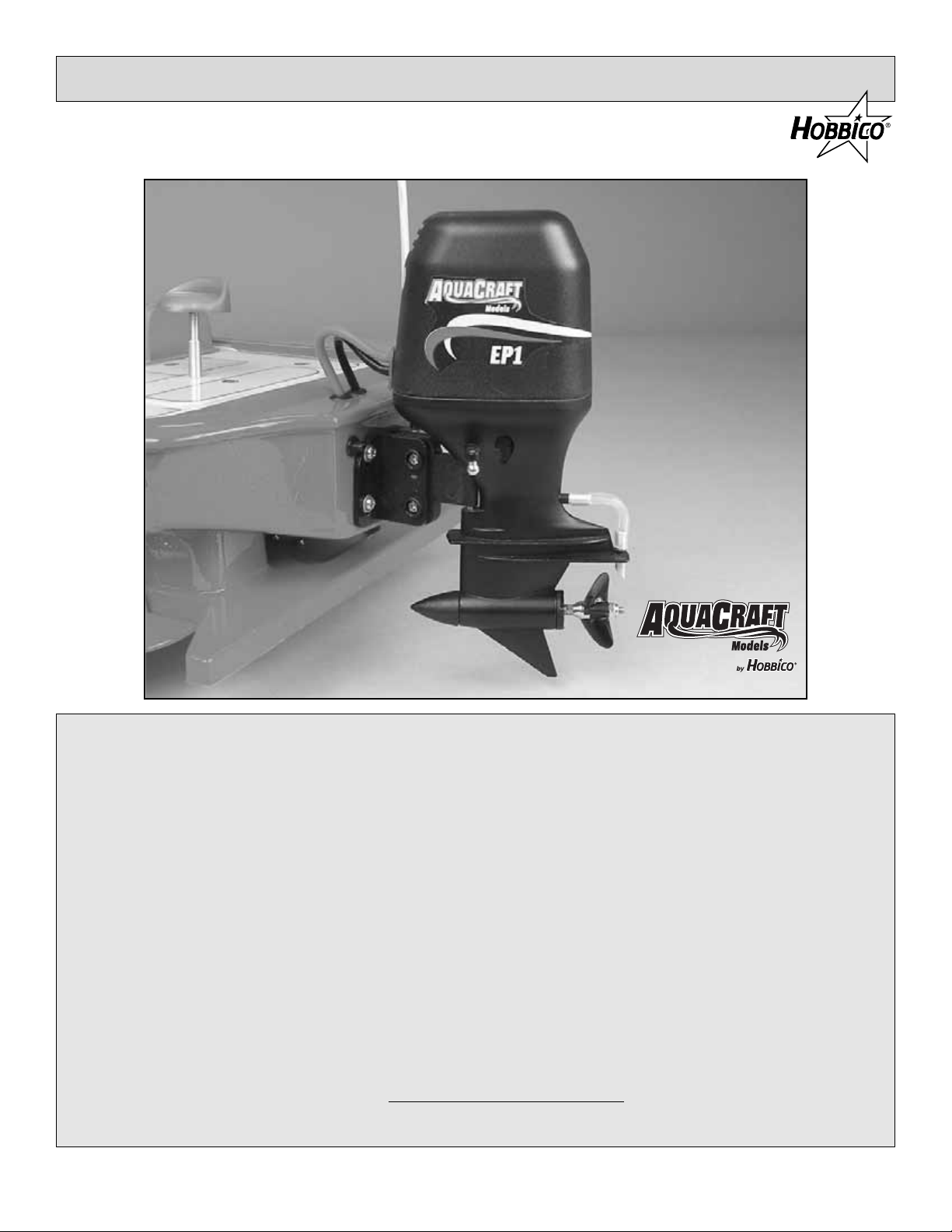
EP1™Electric
Outboard Motor
Page 2
Thank you for purchasing the AquaCraft EP1! We at AquaCraft
know how exciting a new hobby purchase can be and we know
you’re anxious to get started, but please take time to read these
instructions carefully and completely before attempting to
operate your motor. This manual contains the instructions you
need to safely operate and maintain your motor. As with any
hobby, there is the possibility of injury. Arming yourself with
knowledge is the best way to avoid injury.
PLEASE NOTE: Your hobby dealer cannot accept a return on
the EP1 outboard unit after it has been used.
All pictures, descriptions, and specifications found in this
instruction manual are subject to change without notice.
AquaCraft maintains no responsibility for inadvertent errors in
this manual.
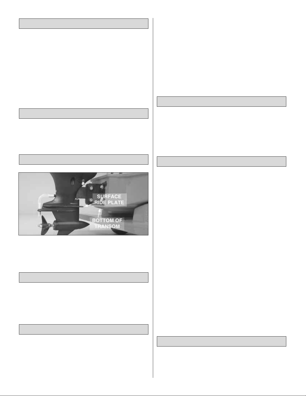
A template has been provided for you on page 3 of this
manual. This will help to accurately place the mounting holes.
Mount the outboard unit in the center of the rear of the boat
and so that the surface ride plate is even with the bottom of
the transom as shown.
The steering control arms of the EP1 outboard unit have been
outfitted with 4.8mm balls, but will accept clevis or Z-bend
links as well. You can attach to either control arm or both but
it is best, of course, to do whichever makes your boat perform
to its fullest potential.
When you are through operating your boat for the day, be sure
to perform these basic maintenance procedures. This will
prolong the life of the EP1 Outboard motor and help to ensure
trouble-free running. Be sure to turn the power “OFF” to
your boat and transmitter before performing any
maintenance.
• Flip your boat over and shake any excess water from the
motor compartment.
• Locate and remove the “end cap” (see “Exploded View”
on page 4) at the base of the outboard by turning it
counterclockwise. This will allow you to release any
water trapped in the gear housing. The “bullet” at the
front of the outboard unit is also removed by
counterclockwise rotation. This allows access to the front
shaft bearing.
• Make sure the propeller and drive dog are free of moss.
After every 10-12 hours of leisurely run time or after a day of
competition, it is a good idea to disassemble and re-lubricate
the gears, shafts, and bearings of the outboard unit with fairly
heavy-duty grease (not oil). Be sure to wipe away any old
grease but DO NOT use any de-greasing agents. Refer to the
“Exploded View” on the back cover for an assembly diagram.
You can increase the performance of the AquaCraft EP1 by
adjusting the ride height or the thrust angle of the propeller.
Making slight adjustments can make major differences, so it is
a good idea to keep a record of any adjustments you make
and how they affect performance. In addition to these
adjustments, performance may also be affected by the weight
distribution of your onboard radio gear, speed control, battery
pack(s), etc…
GO FASTER
The EP1 comes equipped with a 27-turn stock motor but can
be upgraded by replacing it with almost any 550-can size
motor. Be sure to consult the instructions for your speed
control unit to determine motor upgrade limits.
1. After clipping or de-soldering the red (+) and black (-)
motor wires, simply remove the two 3 x 8mm hex head
screws on the underside of the motor compartment and gently
lift out the stock motor. Be sure to remove the water-cooling
coil and jacket from the stock motor and place it on the
upgrade motor before installation.
2. Solder the red (+) and black (-) motor wires to the proper
wiring lugs and attach the upgrade motor to the outboard unit
with the two 3 x 8mm hex head screws.
PLEASE READ BEFORE running the EP1 on your model:
• NEVER attempt to swim after a stalled or capsized boat!
Wait patiently for the wind currents to return the boat to
SAFETY PRECAUTIONS
GETTING MORE OUT OF YOUR EP1
REGULAR MAINTENANCE
BASIC MAINTENANCE
STEERING LINKAGE
EP1 INSTALLATION
SPECIFICATION & DESCRIPTION CHANGES
INTRODUCTION
2
Page 3

shore or use a tennis ball attached to the end of a fishing
rod to retrieve a stalled or capsized boat.
• It is dangerous to operate any R/C model at any time that
there is not sufficient light.
• R/C models produce vibrations which will cause screws,
nuts, bolts, etc, on your model to become loose over
time. It is important to make sure that all hardware is
secure before operating your model.
• The edges of the propeller are very sharp and can cut your
fingers if you are not careful. At no time should you ever
attempt to stop the prop with your hand. In the event that
weeds become entangled in the propeller, turn the EP1’s
power “OFF” before attempting to remove them.
• Total run time of the EP1 can vary depending upon what
battery pack and ESC combination you are using. When
you notice a decrease in power or sluggish steering
response, it means the battery pack is nearly drained and
it’s time to head for shore. As soon as the boat reaches
shore, turn off the power to the boat’s receiver and
transmitter (in that order).
• CAUTION: Your motor and battery may be hot! Allow
them to cool for a few minutes before attempting to
remove the battery pack.
• Adult supervision is strongly recommended! Children
should be warned about the dangers of playing in close
proximity to water.
• R/C boats are controlled by radio signals, which are
susceptible to possible interference from other R/C
transmitters, paging systems, or other electrical noise.
Before turning your radio transmitter and receiver on,
make sure no one else in the area is operating a radio on
the same frequency (channel).
• Do not touch the propeller anytime the electronics are
turned “ON.” Pay close attention to items such as loose
clothing, shirt sleeves, ties, scarves, long hair or any
loose objects that may come in contact with the spinning
propeller. If your fingers, hands, etc. come in contact
with the spinning propeller, you may be severely injured.
• The speed and mass of R/C boats can inflict property
damage and severe personal injury if a collision occurs.
Never run an R/C boat in the presence of swimmers or
where the possibility of collision with people, wildlife, or
property exists.
• Electric motors can generate considerable heat. Do not
touch any part of your motor until it has cooled.
Touching the motor immediately after running the boat
may result in a serious burn.
If the buyer is not prepared to accept the liability associated
with the use of this product, the buyer is advised to return
the EP1 immediately in new and unused condition to the
place of purchase.
To order replacement parts for the AquaCraft EP1, use the order
numbers in the Replacement Parts List that follows. Replacement
parts are available only as listed and can be purchased from
hobby shops or mail order/Internet order firms. Hardware items
(screws, nuts, bolts) are also available from these outlets. If you
need assistance locating a dealer to purchase parts, visit
www .hobbico.com and click on “Where to buy.” If this kit is
missing parts, contact Hobbico Product Support.
Replacement Parts List
Order # Item Description
HCAB7861 EP1 Outboard Motor Unit *This is the part number
for the entire unit.
HCAB6457 Outboard Upper Cover #1
HCAB7857 Outboard Lower Unit #2
HCAB7750 Propeller Set #16,17,18,19 x2
HCAB7856 Ball Bearings #G x4
HCAB3479 Motor #3
HCAB7858 Motor Coupler & Gasket #6, A, #7
HCAB8100 Transom Mount #22, C x2, D x2
HCAB7801
Linkage Ball Studs & Linkages
#23 x2, E x2, F x2
HCAZ3023 Instruction Manual
Hardware Listing
A. 3 x 3mm Set Screw
B. 3 x 8mm Hex Head Screw
C. 3 x 16mm Hex Head Screw
D. 3mm Nylon Insert Locknut
E. 2mm Nut
F. 2 x 8mm Screw
G. 5 x 10mm Ball Bearing
OUTBOARD MOTOR TEMPLATE
ORDERING REPLACEMENT PARTS
3
Page 4

EXPLODED VIEWS
 Loading...