

AquaCraft Air Force User Manual

Before Building
We want the assembly and operation of this airboat to be a success so BEFORE removing any parts from the parts bags,
please read this manual thoroughly to familiarize yourself with the model. If for any reason you think this model is not for
you, return it to your local dealer immediately. PLEASE NOTE: Your hobby dealer cannot accept a return on any model
after assembly has begun.
Warranty
AquaCraft™will warrant this kit for 90 days after the date of purchase from defects in materials or workmanship.
AquaCraft will either repair or replace, at no charge, the incorrectly made part.
Make sure you save the receipt or invoice you were given when you bought your model! It is your proof of purchase
and we must see it before we can honor the warranty.
To return your Air Force for repairs covered under warranty you should send your boat to:
Hobby Services
1610 Interstate Drive
Champaign, Illinois 61822
Attn: Service Department
Phone: (217) 398-0007 9:00 am - 5:00 pm Central Time M-F
E-mail: hobbyservices@hobbico.com
HCAZ3011 for HCAB5027/HCAB27**Entire Contents © Copyright 2002 v1.1
ASSEMBLY AND OPERATION MANUAL
™
™

INTRODUCTION ..............................................................2
SAFETY PRECAUTIONS......................................................2
HELPFUL HINTS ................................................................2
REPAIR SERVICE ................................................................3
SPECIFICATION & DESCRIPTION CHANGES ..................3
SCREW INFORMATION ....................................................3
BOAT TERMINOLOGY ......................................................3
REQUIRED FIELD EQUIPMENT ........................................3
TOOLS YOU WILL NEED ..................................................3
FINISHING THE READY-TO-RUN AIR FORCE ..................4
Final Assembly ..............................................................4
FINISHING THE PRE-BUILT AIR FORCE ............................6
Additional Required Items ..............................................6
ENGINE POD ASSEMBLY & INSTALLATION ....................6
INSTALL THE SERVOS ........................................................8
INSTALL THE RADIO GEAR ..............................................9
RUNNING THE ENGINE....................................................9
BREAKING IN THE ENGINE ............................................11
ENGINE MAINTENANCE ................................................11
RUNNING THE AIR FORCE ............................................12
ORDERING REPLACEMENT PARTS..................................13
ENGINE TROUBLESHOOTING ........................................14
ENGINE MOUNTING TEMPLATE ....................................15
Thank you for purchasing the AquaCraft Air Force™ by
Hobbico®! This manual contains the instructions you need to
safely build, operate, and maintain your nitro R/C airboat.
Read
over this manual thoroughly before operating the Air Force.
• Use care to avoid touching the propeller anytime the
engine is running. Pay equally close attention to items
such as loose clothing, shirt sleeves, ties, scarves, long
hair or loose objects such as screwdrivers or pencils that
may fall out of shirt or jacket pockets on to the spinning
prop. If your fingers, hands, etc. come in contact with the
spinning propeller, you may be severely injured. Make all
engine adjustments from behind the rotating propeller.
• Because of the speed and mass of this boat, it is capable
of inflicting property damage and severe personal injury
if a collision occurs. Never run this boat in the presence
of swimmers or where the possibility of collision with
people or property exists.
• This boat is controlled by radio signals, which are subject
to possible interference from other R/C transmitters,
paging systems or other electrical noise. Before turning
your radio on, make sure no one else in the area is
operating a radio on the same frequency (channel).
• A weakened or loose propeller may disintegrate or be
thrown off. Since propeller tip speeds with powerful
engines may exceed 600 feet per second, it must be
understood that such a failure can result in serious injury.
• Model engine fuel is poisonous. Do not allow it to come
into contact with the eyes or mouth. Always store fuel in a
clearly marked container and out of the reach of children.
• Model engine fuel is highly flammable. Keep it away
from open flame, excessive heat, sources of sparks, or
anything else that might ignite it. Do not smoke or allow
anyone else to smoke in close proximity to open fuel.
Make sure that fuel lines are in good condition so that
fuel will not leak onto a hot engine causing a fire.
• Never operate your engine in an enclosed space. Model
engines, like automobile engines, exhaust deadly carbon
monoxide. Run your engine only in an open area.
• Model engines generate considerable heat. Do not touch
any part of your engine until it has cooled. Touching the
muffler, cylinder head, or exhaust header may result in a
serious burn.
• Use safety glasses when starting or running engines. The
propeller may throw loose material such as sand or
gravel into your face.
• Use a “safety stick” or electric starter to start the engine.
Do not use your fingers to flip the propeller. Make certain
that the glow plug clip or connector is securely in place
so that it does not pop off or otherwise get into the
running propeller.
If the buyer is not prepared to accept the liability associated
with the use of this product, the buyer is advised to return
this kit immediately in new and unused condition to the
place of purchase.
• Avoid working over a deep pile carpet. If you drop a
small part or screw, it will be difficult to find.
• Place a mat or towel over your work surface. This will prevent
parts from rolling off and will protect the work surface.
• Avoid running the boat in cold weather. The hull and
other plastic parts can become brittle at low
temperatures. In addition, grease and oil become thick,
causing premature wear and poor performance.
• Test fit all parts before attaching them permanently.
HELPFUL HINTS
SAFETY PRECAUTIONS
INTRODUCTION
TABLE OF CONTENTS
2

Repair service is available anytime.
After the 90-day warranty, you can still have your Air Force
repaired for a small charge by the experts at AquaCraft’s
authorized repair facility, Hobby Services, at the address
listed on the front page of this manual.
To speed up the repair process, please follow the instructions
as listed below.
1. Under all circumstances return the ENTIRE system;
boat and radio.
2. Make sure the transmitter is turned off, all batteries are
removed and fuel is drained from the tank.
3. Send written instructions which include: a list of all
items returned, a THOROUGH explanation of the
problem, the service needed and your phone number
during the day. If you expect the repair to be covered
under warranty, be sure to include a proof-of-purchase
date (your store receipt or purchase invoice).
4. Also be sure to send your full return address.
All pictures, descriptions, and specifications found in this
instruction manual are subject to change without notice.
AquaCraft maintains no responsibility for inadvertent errors in
this manual.
Do not use too much force when tightening self-tapping
screws into plastic or fiberglass. Over tightening will cause
the threads in the plastic to strip. We recommend that you
stop turning a self-tapping screw once you feel some
resistance as the head of the screw comes in contact with the
plastic. Do not use powered screwdrivers when assembling
this kit. They tend to over tighten the screws. Do not use
thread-locking compound on self-tapping screws. The threadlocking compound may damage the plastic. IMPORTANT:
Use thread lock on any fastener that is threaded into metal or
fastened with a nut. Vibration from the engine will cause the
screws to loosen if thread-locking compound is not used.
BOW: The front of the boat
STERN: The back of the boat
PORT: This is the left side of the boat when aboard and facing
the front (bow).
STARBOARD: This is the right side of the boat when aboard
and facing the front (bow).
HULL: The body of the boat.
DECK: The top of the boat
❏ HCAP2520 Hot Shot
™
2 Glow starter
❏ HCAP3335 Safety Stick Engine Starter
❏ HCAP3015 Hand crank fuel pump
❏Fuel (10-20% nitromethane with at least 18% lubricant)
Optional Items:
❏ HCAP3200 Torqmaster
™
90 Deluxe Electric Starter
❏ HCAP0800 Torqmaster Hobby Battery (12 volt, 7 Ah)
❏ HCAP0200 Charger for Torqmaster Battery
❏ HCAP3105 Top Fueler
™
6/12V Electric Fuel Pump
Other Useful Items to Have on Hand:
❏APCQ1108 11 x 8 Propellers
❏ OSMG2691 #8 Standard long glow plugs
❏ GPMQ4131 Fuel tubing
❏ HCAQ2000 #32 Rubber bands
❏ HCAP3000 After Run Engine Oil
❏ Phillips head screwdriver (HCAR1022)
❏Thin CA (GPMR6002)
❏ 4-way wrench (HCAP2550)
❏ Needle-nose pliers (HCAR0625)
❏Adjustable wrench or 5.5mm wrench
❏ 2mm drill bit (pre-built version only)
❏ 3mm drill bit (pre-built version only)
TOOLS YOU WILL NEED
REQUIRED FIELD EQUIPMENT
BOAT TERMINOLOGY
SCREW INFORMATION
SPECIFICATION & DESCRIPTION CHANGES
REPAIR SERVICE
3
Note: If you have the prebuilt version, proceed to page 6.
Engine and Propeller Installation
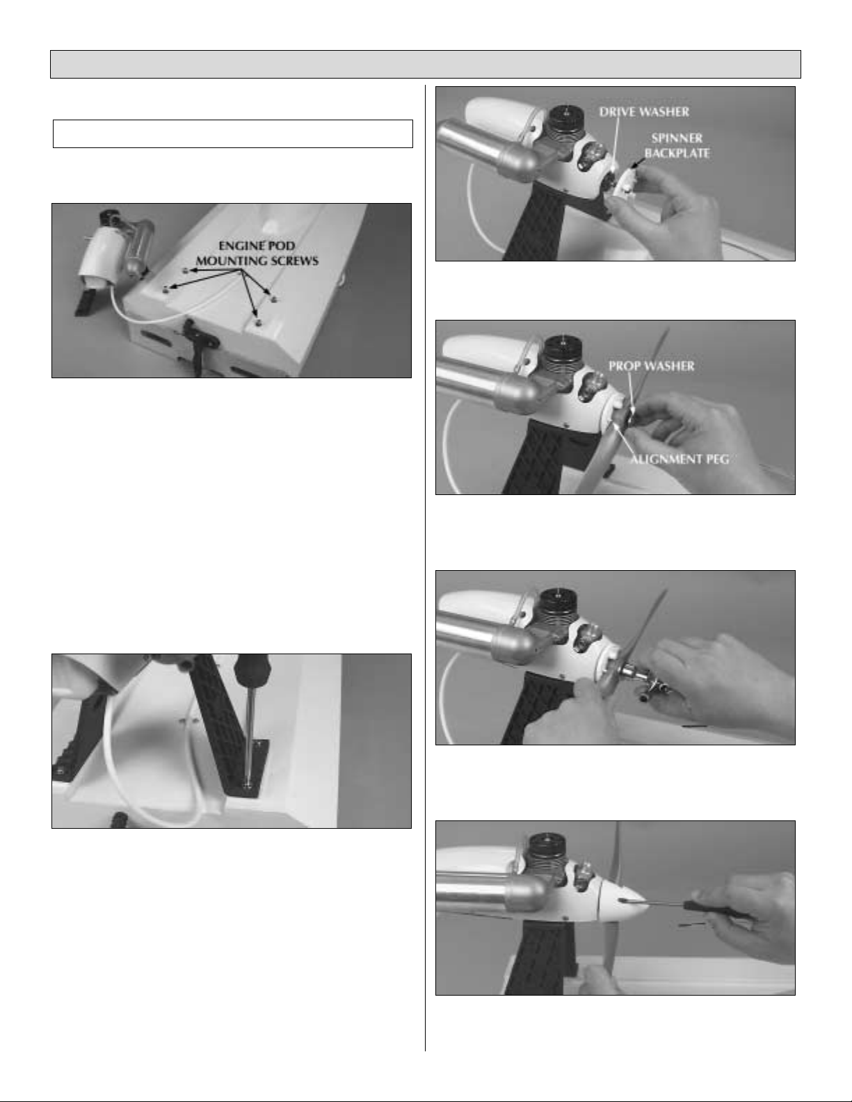
❏ 1. Looking down at the top (deck) of the hull, remove the
four large mounting screws with washers located toward the
rear of the hull (stern).
❏ 2. Place the engine pod assembly onto the hull lining up the
four holes and making sure that the engine points forward,
toward the front of the hull (bow). The engine will appear to point
slightly to the starboard side (right). This is done deliberately to
counter the torque of the engine. Check the alignment by looking
down on the deck and engine from overhead.
❏ 3. Install the four large mounting screws and washers.
Tighten them completely to make sure that the engine pod is
securely fastened to the hull.
❏ 4. Locate the spinner assembly and propeller. Remove the
propeller (prop) nut and washer from the crankshaft of the engine.
❏ 5. Separate the spinner assembly by removing the two
small self-tapping screws.
❏ 6. Place the spinner backplate onto the crankshaft so that
it rests against the drive washer.
❏ 7. Place the propeller onto the crankshaft so that the
blades rest against the alignment pegs of the backplate and
replace the prop washer.
❏ 8. Replace the prop nut. IMPORTANT: Tighten the prop
nut firmly.
❏ 9. Place the spinner cone over the prop so that the blades
of the prop fit into the notches of the cone. Replace the two
spinner assembly screws. The cone should sit flush against the
FINAL ASSEMBLY
4
FINISHING THE READY-TO-RUN AIR FORCE
backplate. If you see a gap, check to make sure that the prop
is installed correctly.
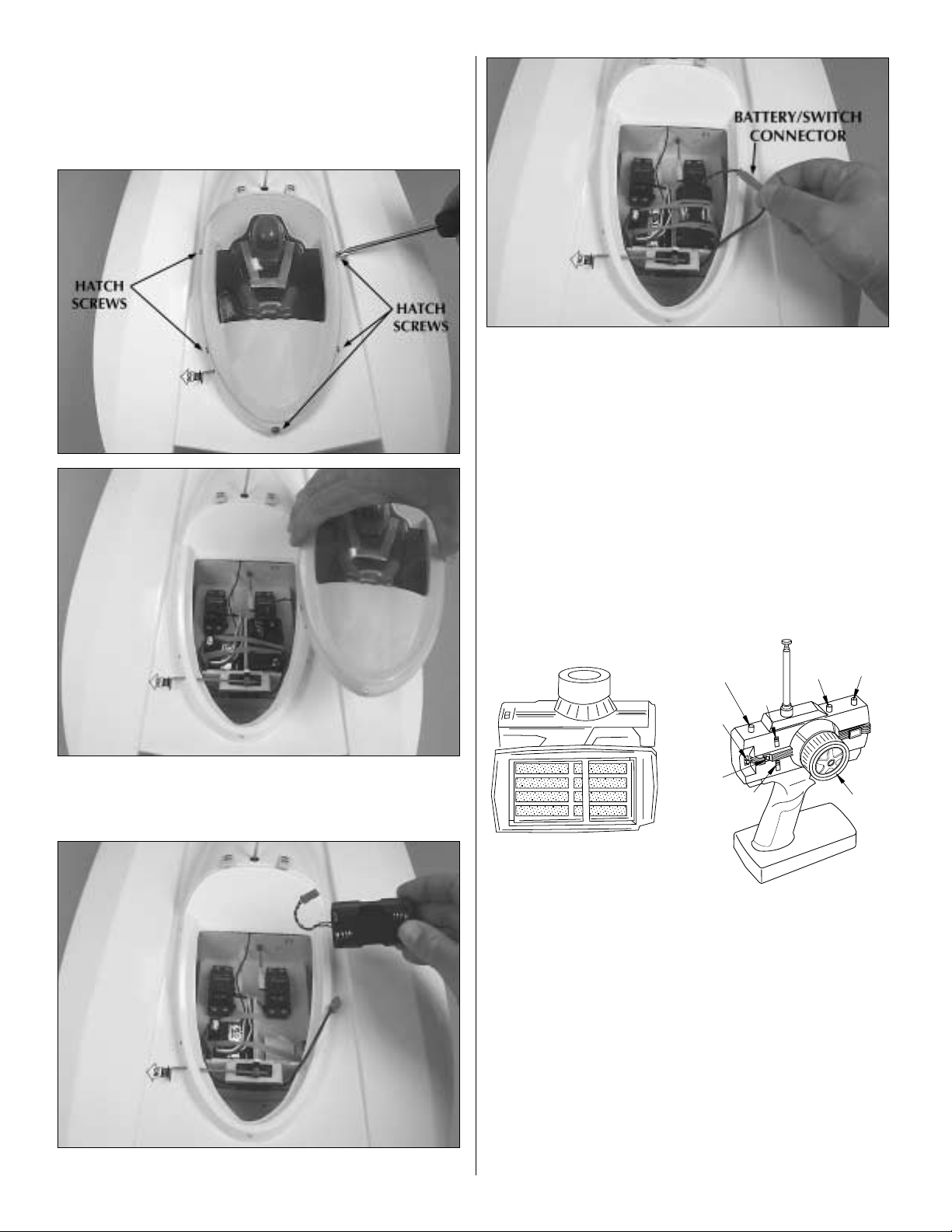
Installation of Batteries
❏ 1. Remove the five hatch screws and lift the canopy
assembly from the deck.
❏ 2. Remove the battery box. Do not cut the rubber bands.
❏ 3. Install four new “AA” batteries into the battery box and
re-install the battery box into the boat. There is hook and loop
material provided with the model to make your battery box
extra secure. Make sure to plug the battery box connector
into the switch connector.
❏ 4. Replace the canopy and secure it with the five hatch
screws.
Transmitter Assembly
❏ 1. Remove the transmitter antenna from the parts bag and
screw it into the top of the transmitter as shown. To ensure
that the antenna is attached, lightly pull on the base of the
antenna. If it slides out, it is not installed properly.
❏ 2. Slide off the battery door on the bottom of the
transmitter.
Install eight new “AA” batteries into the transmitter. Re-install
the battery door onto the bottom of the transmitter.
❏ 3. Turn the transmitter on using the switch on the front. The
red LED light next to the on/off switch should light up. If the
LED does not light up, turn the transmitter off and check to
make sure that the batteries are installed properly. If you see a
flashing LED, the batteries are low and need to be replaced.
Check the Radio System:
• Pull the on/off switch located on the boat to the
“ON” position.
5
ANTENNA
STEERING RATE
(D/R)
STEERING
REVERSE
SWITCH
ON/OFF
SWITCH
POWER LED
(RED)
THROTTLE
REVERSE
SWITCH
Install (8) new "AA" batteries
STEERING
TRIM
THROTTLE
TRIM
STEERING
 Loading...