

Page 1
Model Number: HRS-75 5T
P/N 8893919 Rev A 08/10
1
Page 2
Page 3
Description Page
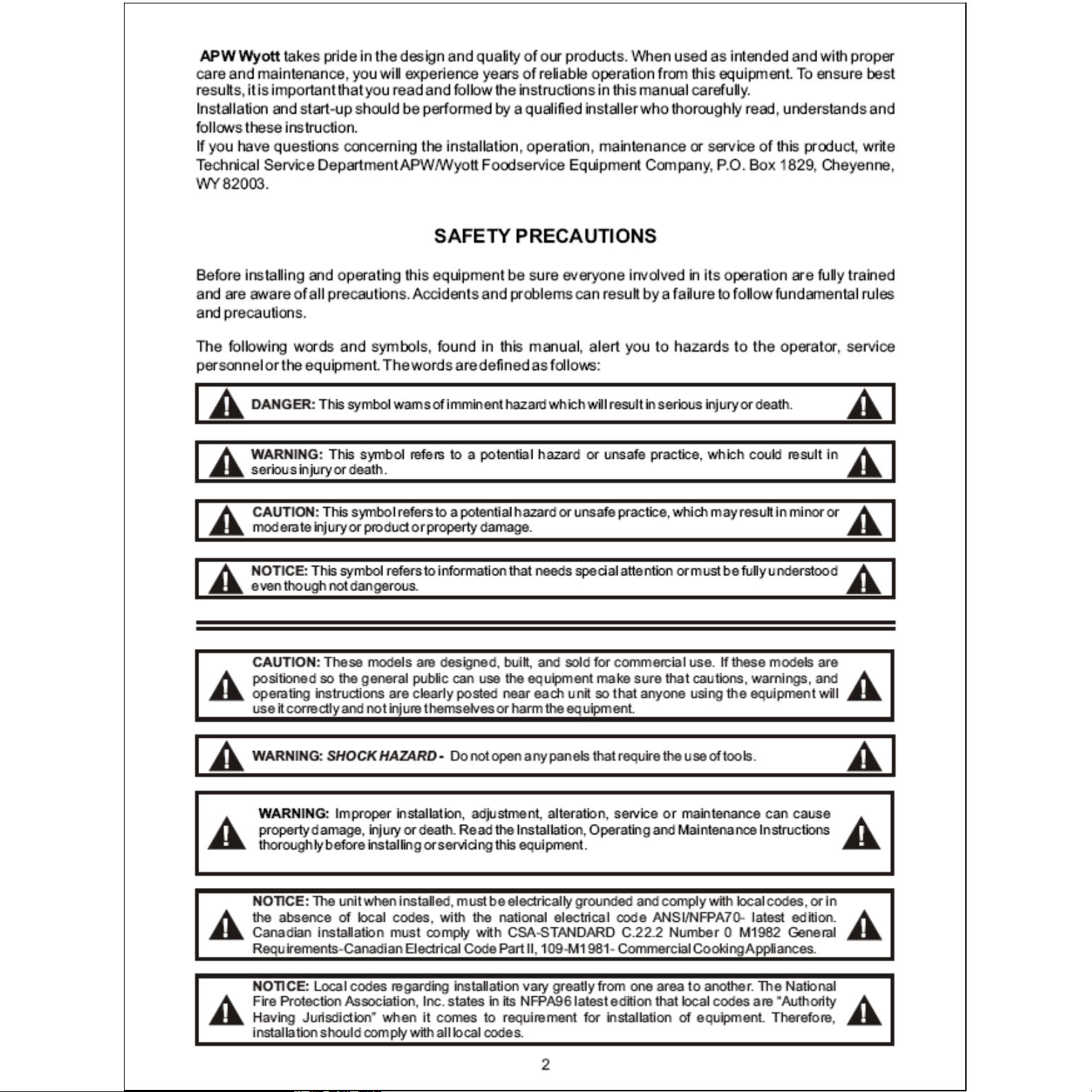
Safety Precautions ........................................................................2
Specifications..........................................................................................3
General Installation Instruction.....................................4
Installation.....................................................................................................5
Operation.........................................................................................................5
Cleaning............................................................................................................5
Service................................................................................................................6
Exploded View..........................................................................................7
Parts List..........................................................................................................8
Wiring Diagram........................................................................................9
Warranty............................................................................................................10
Model WIDTH DEPTH HEIGHT VOLTAGE AMPS
HRS-75 5T 36.00" 29.56" 10.875" 208/240 9.0/10.4
SPECIFICATION
3
Page 4

4
Page 5

There are three simple controls on the front of this unit: a switch, which controls the tube
rotation, and two adjustable heat controls which activates the two banks of heating
elements in the roller tubes. Both heat controls have a light above them indicating either
"Front or Back". The front heat contol activates the first 8 tubes. The back control activates
the remaining 8 tubes. Each bank of tubes can be heated independently of the others and
at seperate temperature settings. Variation in voltage and ventillation make experimenting
the best guide to power level adjustment.
5
Page 6

6
Page 7

EXPLODED VIEW
7
Page 8

PARTS LIST
Item P/N Description Qty
2 1328200 Infinite Switch 2
3 8705610 Knob 2
12 21831906 Bottom Cover 1
13 8968900 Strain Relief 90 deg 1
14 1542005 Cordset, 14/3 500C W/nema 6-15P 1
15 1331800 Switch Rocker 1
16 8816555 Decal, Front Panel 1
17 1513903 Light, Indicator, 250V 2
20 21752487 Panel, End 2
21 21792239 Element Retainer 2
22 21792234 Element Support 2
23 21793400 Bearing, Hot Rod 8
24 21748900 Bearing, Hot Rod 24
25 422300 Seal, Grease 32
26 21831907 Pan, Drip 1
27 21831912 Roller Tube, Xylan Coating 16
28 1431455 Element, 220V 16
32 1211700 Motor, Gear 240V 50/60HZ 1
33 21792336 Chain Guide Bracket 2
34 21748312 Bracket, Gage 2
35 21792251 Chain Drive, 31-1/2" 126 Pitches 2
36 21792309 Tensioner 2
37 21792308 Bushing 2
38 21748501 Sprocket 2
39 8414700 Nut #10-32 2
40 21831905 Leg, 6" 4
41 9866400 Bushing, Snap Heyco #2820 4
42 21748510 Sprocket, 17 Tooth W/Hub 2
44 21750716 Insulation 2
49 1211800 Motor, Gear 240V 50/60HZ 1
8
Page 9

WIRING DIAGRAM
5 11
3
5
FRONT MOTOR
3
PILOT
L1
H2
6
10
L2
4
8
5
PILOT
10
10
FRONT
8
5
2
10
H1
7
9
10
1
10
PILOT L1
PILOT
H1
L2
11
12
9
10
H2
4
10
REAR
6
M
FRONT
11 11
M
REAR
REAR MOTOR
1
12
7
13
14
15
9
Page 10

10
 Loading...