

Page 1
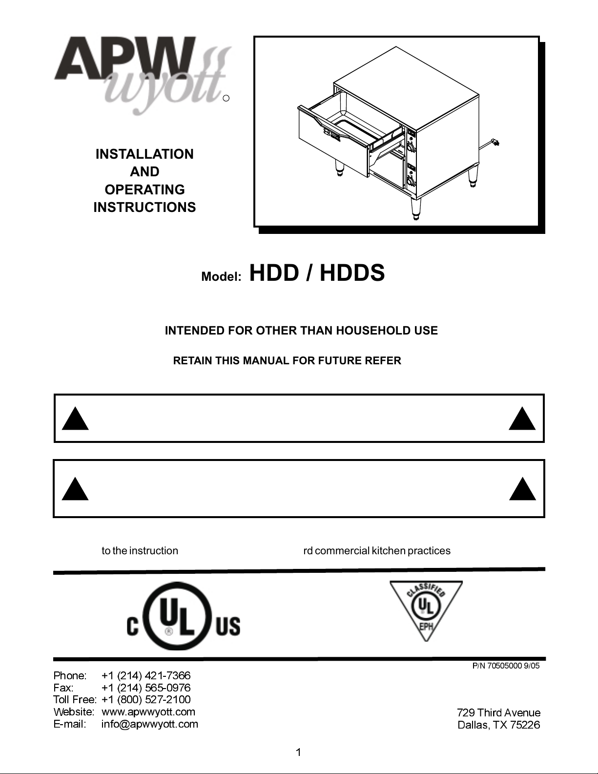
INSTALLATION
AND
OPERATING
INSTRUCTIONS
HOLDING DRAWERS
INTENDED FOR OTHER THAN HOUSEHOLD USE
RETAIN THIS MANUAL FOR FUTURE REFERENCE
UNIT MUST BE KEPT CLEAR OF COMBUSTIBLES AT ALL TIMES
R
Model: HDD / HDDS
FOR YOUR SAFETY: Do not store or use gasoline or other flammable vapors and
liquids in the vicinity of this or any otherappliance.
WARNING: Improper installation, adjustment, alteration, service or maintenance can
cause property damage, injury or death. Read the Installation, Operating and
Maintenance Instructions thoroughlybefore installing or servicing this equipment.
This equipment has been engineered to provide you with year-round dependable service when used
according to the instructions in this manual and standard commercial kitchen practices.
ANSI/NSF4
P/N 70505000 9/05
Phone: +1
Fax: +1 (214) 565-0976
Toll Free: +1 (800) 527-2100
Website: www.apwwyott.com
E-mail: info@apwwyott.com
(214) 421-7366
APW WYOTT
729 Third Avenue
Dallas, TX 75226
!!
!!
1
Page 2
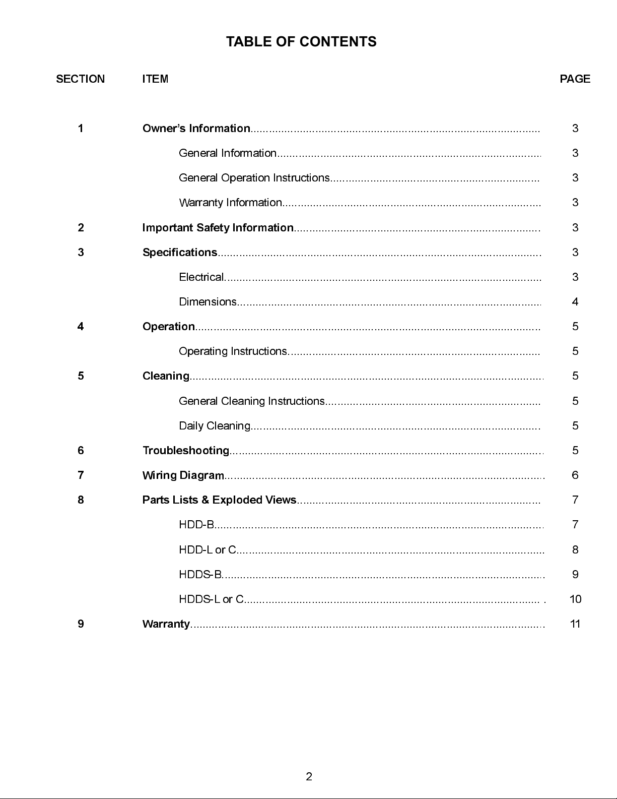
TABLE OF CONTENTS
SECTION
1
2
3
4
ITEM
Owners Information
General Information......................................................................................
General Operation Instructions.....................................................................
Warranty Information....................................................................................
Important Safety Information
Specifications
Electrical.......................................................................................................
Dimensions...................................................................................................
Operation
Operating Instructions...................................................................................
.........................................................................................................
.................................................................................................................
..............................................................................................
.................................................................................
PAGE
3
3
3
3
3
3
3
4
5
5
5
6
7
8
9
Cleaning
Troubleshooting
Wiring Diagram
Parts Lists & Exploded Views
Warranty
...................................................................................................................
General Cleaning Instructions.......................................................................
Daily Cleaning...............................................................................................
......................................................................................................
........................................................................................................
................................................................................
HDD-B...........................................................................................................
HDD-L or C....................................................................................................
HDDS-B.........................................................................................................
HDDS-L or C..................................................................................................
...................................................................................................................
5
5
5
5
6
7
7
8
9
10
11
2
Page 3
1. OWNER’S INFORMATION
General Information:
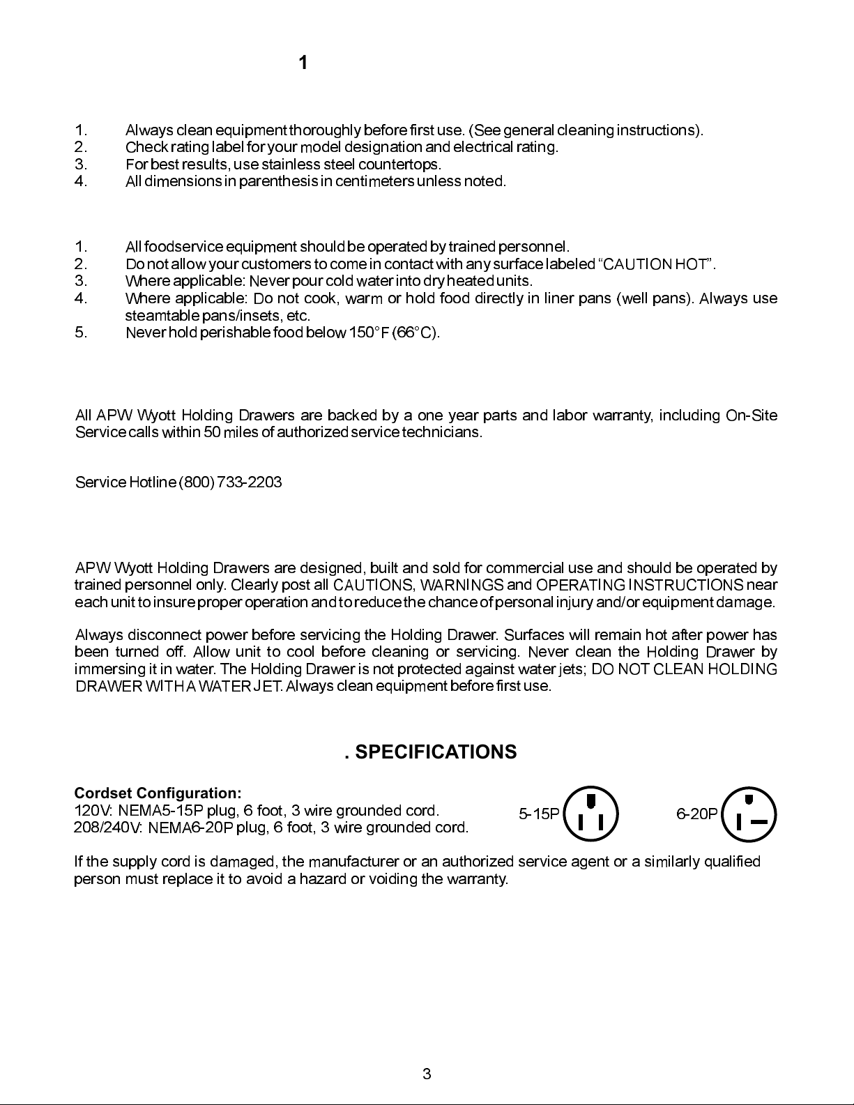
1. Alwaysclean equipment thoroughlybefore first use. (See general cleaning instructions).
2. Checkrating label for yourmodel designation and electrical rating.
3. Forbest results, usestainless steel countertops.
4. Alldimensions in parenthesisin centimeters unlessnoted.
General Operation Instructions:
1. Allfoodservice equipment shouldbe operated by trained personnel.
2. Donot allow your customersto come in contactwith any surfacelabeled CAUTION HOT.
3. Whereapplicable: Never pourcold water into dry heated units.
4. Where applicable: Do not cook, warm or hold food directly in liner pans (well pans). Always use
steamtablepans/insets,etc.
5. Neverhold perishable food below 150°F (66°C).
Warranty Information:
Reliability Backed ByAPW Wyott’s Warranty:
All APW Wyott Holding Drawers are backed by a one year parts and labor warranty, including On-Site
Servicecalls within 50 milesof authorized service technicians.
Service Information:
ServiceHotline (800) 733-2203
2. SAFETY INFORMATION
APW Wyott Holding Drawers are designed, built and sold for commercial use and should be operated by
trained personnel only. Clearly post all CAUTIONS, WARNINGSand OPERATING INSTRUCTIONS near
eachunit to insure properoperation and to reducethe chance of personalinjury and/or equipmentdamage.
Always disconnect power before servicing the Holding Drawer. Surfaces will remain hot after power has
been turned off. Allow unit to cool before cleaning or servicing. Never clean the Holding Drawer by
immersing it in water. The Holding Drawer is not protected against water jets; DO NOT CLEAN HOLDING
DRAWERWITHAWATERJET.Always clean equipment before first use.
3. SPECIFICATIONS
Cordset Configuration:
120V: NEMA5-15P plug, 6 foot, 3 wire grounded cord.
208/240V: NEMA6-20P plug, 6 foot, 3 wire grounded cord.
If the supply cord is damaged, the manufacturer or an authorized service agent or a similarly qualified
person must replace it to avoid a hazard or voiding the warranty.
5-15P 6-20P
3
Page 4
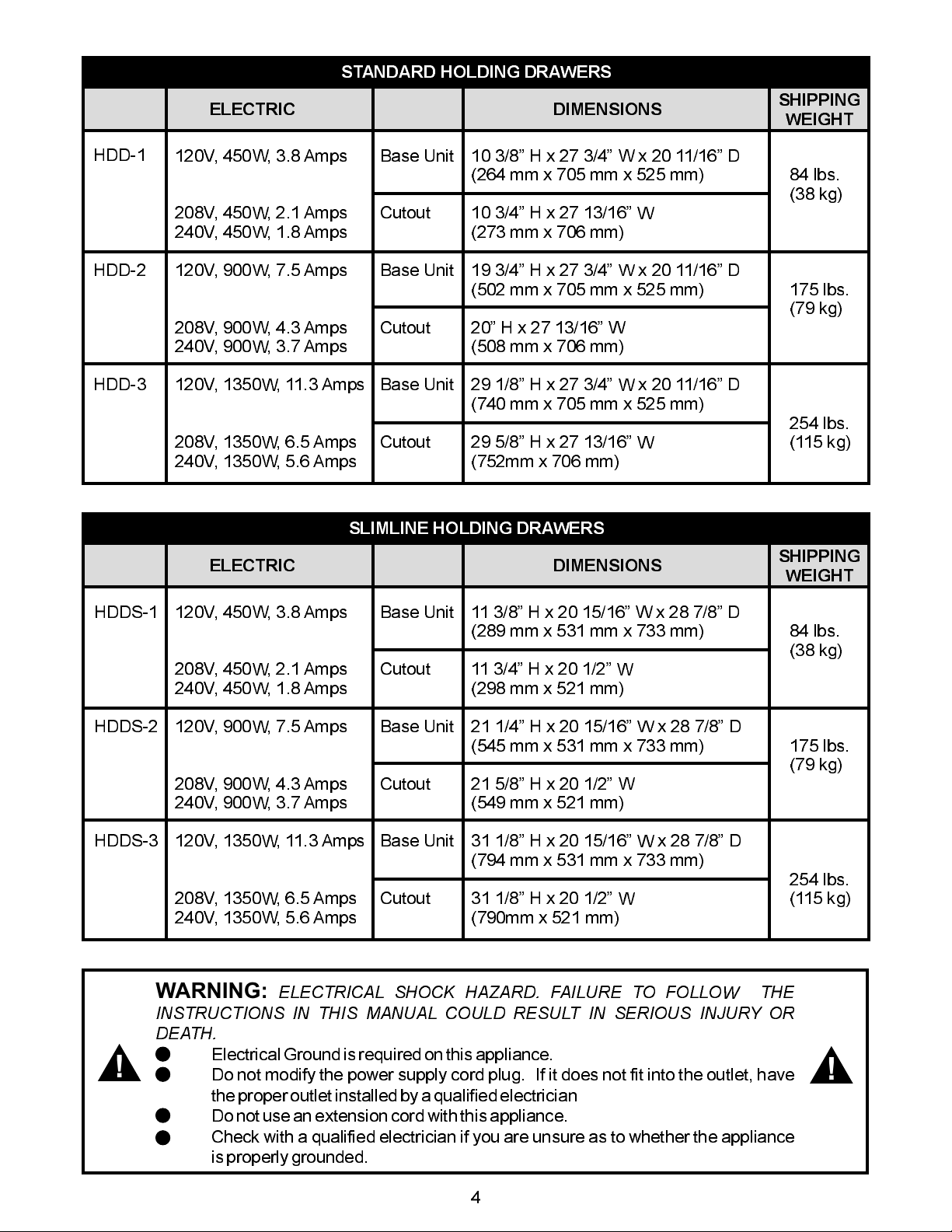
STANDARD HOLDING DRAWERS
HDD-1
HDD-2
HDD-3
ELECTRIC
120V, 450W, 3.8 Amps
208V, 450W, 2.1 Amps
240V, 450W, 1.8 Amps
120V, 900W, 7.5 Amps
208V, 900W, 4.3 Amps
240V, 900W, 3.7 Amps
120V, 1350W, 11.3 Amps
208V, 1350W, 6.5 Amps
240V, 1350W, 5.6 Amps
SLIMLINE HOLDING DRAWERS
Base Unit
Cutout
Base Unit
Cutout
Base Unit
Cutout
DIMENSIONS
10 3/8 H x 27 3/4 W x 20 11/16 D
(264 mm x 705 mm x 525 mm)
10 3/4 H x 27 13/16 W
(273 mm x 706 mm)
19 3/4 H x 27 3/4 W x 20 11/16 D
(502 mm x 705 mm x 525 mm)
20 H x 27 13/16 W
(508 mm x 706 mm)
29 1/8 H x 27 3/4 W x 20 11/16 D
(740 mm x 705 mm x 525 mm)
29 5/8 H x 27 13/16 W
(752mm x 706 mm)
SHIPPING
WEIGHT
84 lbs.
(38 kg)
175 lbs.
(79 kg)
254 lbs.
(115 kg)
HDDS-1
HDDS-2
HDDS-3
!
ELECTRIC
120V, 450W, 3.8 Amps
208V, 450W, 2.1 Amps
240V, 450W, 1.8 Amps
120V, 900W, 7.5 Amps
208V, 900W, 4.3 Amps
240V, 900W, 3.7 Amps
120V, 1350W, 11.3 Amps
208V, 1350W, 6.5 Amps
240V, 1350W, 5.6 Amps
WARNING:
INSTRUCTIONS IN THIS MANUAL COULD RESULT IN SERIOUS INJURY OR
DEATH.
ElectricalGround is requiredon this appliance.
Do not modify the power supply cord plug. If it does not fit into the outlet, have
theproper outlet installedby a qualified electrician
Donot use an extensioncord with this appliance.
Check with a qualified electrician if you are unsure as to whether the appliance
is properly grounded.
ELECTRICAL SHOCK HAZARD. FAILURE TO FOLLOW THE
Base Unit
Cutout
Base Unit
Cutout
Base Unit
Cutout
11 3/8 H x 20 15/16 W x 28 7/8 D
(289 mm x 531 mm x 733 mm)
11 3/4 H x 20 1/2 W
(298 mm x 521 mm)
21 1/4 H x 20 15/16 W x 28 7/8 D
(545 mm x 531 mm x 733 mm)
21 5/8 H x 20 1/2 W
(549 mm x 521 mm)
31 1/8 H x 20 15/16 W x 28 7/8 D
(794 mm x 531 mm x 733 mm)
31 1/8 H x 20 1/2 W
(790mm x 521 mm)
DIMENSIONS
SHIPPING
WEIGHT
84 lbs.
(38 kg)
175 lbs.
(79 kg)
254 lbs.
(115 kg)
!
4
Page 5

4. OPERATION
1. Initial heating ofunit may generatesmoke or fumes andmust be donein a wellventilated area.
2. Setthermostat control knob to desired settingand preheat each drawerfor 30 minutes.
3. Place food product directly in stainless steel drawer pans or use any combination of full or fractional
pansup to 6 (152mm) deep.
4. Setfront vent knob to desired position for maintainingfood product moisture.
5. Perforatedpans may be used with damp towel or smallamount of hot water in the drawer pan to prevent
fooddry out.
CAUTION:
6. If too much moisture accumulates around drawer front or vent, reduce temperature setting or move
ventknob to dry position.
Useno more than 1 quart (1 liter) for wet operation.
PRODUCT TEMPERATURE SETTING VENT
Rolls, Bread
Vegetables
Meats
160°-180° F (71°-82° C)
170°-180° F (77°-82° C)
170°-180° F (77°-82° C)
Moist
Moist
Moist
NOTE:
will require adjustment according to
type and quantity of food, and number
of times drawer is opened during
operation.
Temperature and vent settings
5. CLEANING
General Cleaning Instructions:
1. NEVERclean any electrical unit by immersing it in water.Turnoff before surface cleaning.
2. Always clean equipment thoroughly before first use. Clean unit daily. Except where noted on charts:
Use warm, soapy water.Mild cleansers and PLASTIC scouring pads may be used to remove baked-on
foodand water scale.
3. Turn off electrical units before cleaning or servicing. All service should be performed by an APW
authorizedservice agency.
DailyCleaning:
1. FollowGeneral Cleaning instructions(above).
2. Removeany inset pansand drawer pans.Wash thoroughly in the sink or dishwasher.
3. Remove drawers: Remove pans and pan inserts. Extend drawer and lift up on the front to clear the
drawerstop. Lower drawer and pull straight out.
6. TROUBLESHOOTING GUIDE
Alwaysask and check the following:
1. Is the unit connected to a live power source of the proper voltage?
2. Checkthe circuit breaker.
3. Is power switch ON andpilot light glowing?
4. Checkthe rating label. Isthe unit connected tothe correct power source?
5
Page 6

Element
Element
7. WIRING DIAGRAM
Pilot Light
Thermostat
Pilot Light
Thermostat
Element
Pilot Light
L2
Thermostat
L1
6
Page 7

8. PARTS LISTS & EXPLODED VIEWS
ITEM P/N DESCRIPTION
HDD-B PARTS LIST
ITEM P/N DESCRIPTION
1
2
3
4
N/S
N/S
7
8
9
10
11
12
13
14
15
16
17
18
N/A
56505
33976
33952
33993
69120
60113
32490
32491
33359
89145
32438
32437
32439
33962
33980
33960
33997
33981
33961
33998
88852
33932
33933
56530
69145
33938
33944
Rating Label
Thermostat Knob
HDD1B Control Panel
HDD2B Control Panel
HDD3B Control Panel
Thermostat
Insulation
HDD1B Wire Set
HDD2B Wire Set
HDD3B Wire Set
Terminal Block
HDD1B Body Assembly
HDD2B Body Assembly
HDD3B Body Assembly
Top Cover
HDD1B Side Outer Cover Right
HDD2B Side Outer Cover Right
HDD3B Side Outer Cover Right
HDD1B Side Outer Cover Left
HDD2B Side Outer Cover Left
HDD3B Side Outer Cover Left
Bushing, Bronze
Left Drawer Slide
Right Drawer Slide
Indicator Light
Thermometer
Drawer Housing Assembly
Drawer Face Assembly
19
20
21
22
23
24
25
26
27
28
N/S
N/S
N/S
N/S
N/S
N/S
N/S
N/S
N/S
N/S
N/S
89167
33154
33018
33397
33156
54111
54112
54113
33982
33963
33999
33908
33909
33910
88851
89026 Cap Nut
33858
88961
89071
89076
89163
88909
89140
88894
89073
88892
88893
Drawer Vent Knob
Drawer Handle Strip
Drawer Pan
Thermostat & Thermometer Bracket
Element Bracket
120V Heating Element
208V Heating Element
240V Heating Element
HDD1B Front Plate
HDD2B Front Plate
HDD3B Front Plate
HDD3B Front Poly Panel
HDD2B Front Poly Panel
HDD1B Front Poly Panel
Press Stud
Roller, Drawer Slide
Green Ground Nut
#10 Flat Washer
1/4 Internal Star Washer
1/4-20 SS Jam Nut
8-18 X 1/2 Sheet Metal Screw
Cable Tie
1/4-20 X 7/8 Press Stud
8 X 1/2 Screw
1/4-20X1FlatHead SS
1/4-20 Nylon Insert Locknut
13
20
21
18
25
HDD-B EXPLODED VIEW
9
16
23
8
11
2
24
17
22
12
7
27
28
19
14
26
4
3
15
10
7
Page 8

ITEM P/N DESCRIPTION
1
2
3
4
N/S
N/S
7
8
9
10
11
12
13
14
15
16
17
18
19
N/A
56505
33976
33952
33993
69120
60113
33357
33358
33359
33907
32425
32403
32431
33936
33973
33934
33990
33906
88852
32406
32411
56530
69145
70502023
70502030
89167
Rating Label
Thermostat Knob
HDD1B Control Panel
HDD2B Control Panel
HDD3B Control Panel
Thermostat
Insulation
HDD1 Wire Set
HDD2 Wire Set
HDD3 Wire Set
Caster Swival Locking (Opt)
HDD1 Body Assembly
HDD2 Body Assembly
HDD3 Body Assembly
Top Cover
HDD1 Side Outer Cover Panel
HDD2 Side Outer Cover Panel
HDD3 Side Outer Cover Panel
Caster Fixed (Opt)
Bushing, Bronze
Left Drawer Slide
Right Drawer Slide
Indicator Light
Thermometer
Drawer Housing Assembly
Drawer Face Assembly
Drawer Vent Knob
HDD-L or C PARTS LIST
ITEM P/N DESCRIPTION
20
21
22
23
24
N/S
26
27
28
29
30
N/S
N/S
N/S
N/S
N/S
N/S
N/S
N/S
N/S
N/S
N/S
32483
33018
55970
32404
54111
54112
54113
32402
86295
33909
33910
33908
33948
88851
89026
33858
88961
89071
89076
89163
88909
89140
88894
89073
88892
88893
Drawer Handle Strip
Drawer Pan
Cordset 16/3 SJTO
Element Bracket
120V Heating Element
208V Heating Element
240V Heating Element
Element Bracket Large
Legs 4" Black (Std)
HDD1B Front Poly Panel
HDD2B Front Poly Panel
HDD3B Front Poly Panel
Bottom Panel
Press Stud
Cap Nut
Roller, Drawer Slide
Green Ground Nut
#10 Flat Washer
1/4 Internal Star Washer
1/4-20 SS Jam Nut
8-18 X 1/2 Sheet Metal Screw
Cable Tie
1/4-20 X 7/8 Press Stud
8 X 1/2 Screw
1/4-20X1FlatHead SS
1/4-20 Nylon Insert Locknut
21
20
13
18
HDD-L or C EXPLODED VIEW
16
9
8
23
2
24
17
12
29
30
19
14
15
27
28
4
3
22
10
26
7
11
8
Page 9

ITEM P/N
DESCRIPTION
HDDS-B PARTS LIST
ITEM P/N DESCRIPTION
1
2
3
4
N/S
N/S
7
8
9
10
11
12
13
14
15
16
N/A
56505
33351
33387
33331
69120
60113
32490
32491
33359
89145
32477
32474
32480
33301
33302
33309
33316
33304
33311
33318
88852
32443
32448
56530
69145 Thermometer
Rating Label
Thermostat Knob
HDDS1B Control Panel
HDDS2B Control Panel
HDDS3B Control Panel
Thermostat
Insulation
HDDS1B Wire Set
HDDS2B Wire Set
HDDS3B Wire Set
Terminal Block
HDDS1B Body Assembly
HDDS2B Body Assembly
HDDS3B Body Assembly
Top Cover
HDDS1B Side Outer Cover Panel
HDDS2B Side Outer Cover Panel
HDDS3B Side Outer Cover Panel
HDDS1B Front Plate
HDDS2B Front Plate
HDDS3B Front Plate
Bushing, Bronze
Left Drawer Slide
Right Drawer Slide
Indicator Light
17
18
19
20
21
22
N/S
24
25
26
27
N/S
N/S
N/S
N/S
N/S
N/S
N/S
N/S
N/S
N/S
N/S
32456
33366
89167
32483
33018
32404
32402
54114
54115
54116
58168
58169
58170
88851
89026
33858
88961
89071
89076
89163
88909
89140
88894
89073
88892
88893
Drawer Housing Assembly
Drawer Face Assembly
Drawer Vent Knob
Drawer Handle Strip
Drawer Pan
Element Bracket
Element Bracket Large
120V Heating Element
208V Heating Element
240V Heating Element
HDDS1B Front Panel Poly
HDDS2B Front Panel Poly
HDDS3B Front Panel Poly
Press Stud
Cap Nut
Roller, Drawer Slide
Green Ground Nut
#10 Flat Washer
1/4 Internal Star Washer
1/4-20 SS Jam Nut
8-18 X 1/2 Sheet Metal Screw
Cable Tie
1/4-20 X 7/8 Press Stud
8 X 1/2 Screw
1/4-20 X 1 Flat Head SS
1/4-20 Nylon Insert Locknut
13
20
21
HDDS-B EXPLODED VIEW
9
22
8
24
17
12
16
25
4
15
2
3
7
18
19
14
26
27
11
10
9
Page 10

ITEM P/N
DESCRIPTION
HDDS-L or C PARTS LIST
ITEM P/N DESCRIPTION
1
2
3
4
N/S
N/S
7
8
9
10
11
12
13
14
15
16
17
18
19
N/A
56505
33351
33387
33331
69120
60113
33357
33358
33359
33907
32462
32441
32468
33360
33352
33392
33332
33906
88852
32443
32448
56530
69145
32456
33366
89167
Rating Label
Thermostat Knob
HDDS1 Control Panel
HDDS2 Control Panel
HDDS3 Control Panel
Thermostat
Insulation
HDDS1 Wire Set
HDDS2 Wire Set
HDDS3 Wire Set
Caster Swivel Locking (Opt)
HDDS1 Body Assembly
HDDS2 Body Assembly
HDDS3 Body Assembly
Top Cover
HDDS1 Side Outer Cover Panel
HDDS2 Side Outer Cover Panel
HDDS3 Side Outer Cover Panel
Caster Fixed (Opt)
Bushing, Bronze
Left Drawer Slide
Right Drawer Slide
Indicator Light
Thermometer
Drawer Housing Assembly
Drawer Face Assembly
Drawer Vent Knob
20
21
22
23
24
25
26
27
28
29
30
N/S
N/S
N/S
N/S
N/S
N/S
N/S
N/S
N/S
N/S
N/S
32483
33018
89101
32402
54114
54115
54116
86295
55970
85645
32404
58168
58169
58170
88851
89026
33858
88961
89071
89076
89163
88909
89140
88893
88894
89073
88892
Drawer Handle Strip
Drawer Pan
Strain Relief, Bushing .625DD
Element Bracket Large
120V Heating Element
208V Heating Element
240V Heating Element
Legs 4" Black (Std)
Cordset 16/3 SJTO
Cordset 16/3 SJTO
Element Bracket
HDDS1B Front Panel Poly
HDDS2B Front Panel Poly
HDDS3B Front Panel Poly
Press Stud
Cap Nut
Roller, Drawer Slide
Green Ground Nut
#10 Flat Washer
1/4 Internal Star Washer
1/4-20 SS Jam Nut
8-18 X 1/2 Sheet Metal Screw
Cable Tie
1/4-20 Nylon Insert Locknut
1/4-20 X 7/8 Press Stud
8 X 1/2 Screw
1/4-20 X 1 Flat Head SS
13
20
18
21
19
14
30
29
15
9
12
HDDS-L or C EXPLODED VIEW
24
8
27
16
17
3
4
28
2
7
22
23
26
10
11
25
10
Page 11

9. APW WYOTT EQUIPMENT LIMITED WARRANTY
APW Wyott Foodservice Equipment Company warrants it'sequipment against defects in materials and workmanship, subject to the
following conditions:
This warranty applies to the original owner only and is not assignable.
Should any product fail to function in its intended manner under normal use within the limits defined in this warranty, at the option of
APW Wyott such product will be repaired or replaced by APW Wyott or its Authorized Service Agency. APW Wyott will only be
responsible for charges incurred or service performed by its Authorized Service Agencies. The use of other than APW Wyott
Authorized Service Agencies will void this warranty and APW Wyott will not be responsible for such work or any charges associated
with same. The closestAPWWyottAuthorized Service Agent must be used.
This warranty covers products shipped into the 48 contiguous United States, Hawaii, metropolitan areas ofAlaska and Canada. There
will be no labor coverage for equipment located on any island not connected by roadway to the mainland.
Warranty coverage on products used outside the 48 contiguous United States, Hawaii, and metropolitan areas of Alaska and Canada
may vary.ContacttheinternationalAPWWyottdistributor,dealer,or service agency for details.
TimePeriod
One year for parts and one year for labor, effective from the date of purchase by the original owner. The Authorized ServiceAgency
may, at their option, require proof of purchase. Parts replaced under this warranty are warranted for the un-expired portion of the
original product warranty only.
Exceptions
Inall cases, parts covered by extended warranty will be shipped FOB the factory after thefirst year.
Portable Carry In Products
Equipment weighing over 70 pounds or permanently installed will be serviced on-site as per the terms of this warranty. Equipment
weighing 70 pounds or under, and which is not permanently installed, i.e. with cord and plug, is considered portable and is subject to
the following warranty handling limitations. If portable equipment fails to operate in its intended manner on the first day of
connection, or use, at APWWyott'soptionoritsAuthorizedServiceAgency,it will beserviced on site or replaced.
From day two through the conclusion of this warranty period, portable units must be taken to or sent prepaid to the APW Wyott
Authorized Service Agency for in-warranty repairs. No mileage or travel charges are allowed on portable units after the first day of use.
If the customer wants on-site service, they may receive same by paying the travel and mileage charges. Exceptions to this rule: (1)
countertop warmers and cookers, which are covered under the Enhanced WarrantyProgram, and (2) toasters or rollergrills which have
instore service.
Exclusions
The following conditions are not covered by warranty:
If the equipment has been changed, altered, modified or repaired by other than an Authorized Service Agency during or after the
warranty period, then the manufacturer shall not be liable for any damages to any person or to any property, which may result from the
use of the equipment thereafter.
This warranty does not cover services performed at overtime or premium labor rates. Should service be required at times which
normally involve overtime or premium labor rates, the owner shall be charged for the difference between normal service rates and such
premium rates.APWWyottdoesnotassumeanyliability for extended delays in replacing or repairing any items beyond its control.
Inall cases, the use of other than APW WyottAuthorized OEM Replacement Parts will void this warranty.
This equipment is intended for commercial use only.Warrantyisvoidifequipment is installed in other than commercial application.
WaterQualityRequirements
Water supply intended for a unit that has in excess of 3.0 grains of hardness per gallon (GPG) must be treated or softened before
being used. Water containing over 3.0 GPG will decrease the efficiency and reduce the operation life of the unit.
Note: Product failure caused by liming or sediment buildup is not covered under warranty.
THE FOREGOING WARRANTY IS IN LIEU OFANYAND ALL OTHER WARRANTIES EXPRESSED OR IMPLIED
INCLUDING ANY IMPLIED WARRANTY OF MERCHANTABILITY OR FITNESS FOR PARTICULAR PURPOSES
AND CONSTITUTES THE ENTIRE LIABILITY OF APW WYOTT. IN NO EVENT DOES THE LIMITED WARRANTY
EXTEND BEYOND THE TERMS STATED HEREIN.
*Gas/Electric Cookline:
component parts, except switches and thermostats. (2 additional years on parts only. No labor on second orthird year.)
*BroilerBriquettes,
*Heat Strips:
*GlassWindows, Doors, Seals, Rubber Seals, Light Bulbs:
*Equipment failure relating to improper installation, improper utility connection or supply and problems due to
ventilation.
*Equipment that has not been properly maintained, calibration of controls, adjustments, damage from improper cleaning
and water damage to controls.
*Equipment that has not been used in an appropriate manner, or has been subject to misuse or misapplication, neglect,
abuse, accident, alteration, negligence, damage during transit, delivery or installation, fire, flood, riot or act of god.
*Equipment that has the model number or serial number removed or altered.
Models FD, FDL, FDD, FDDL. Two(2)YearWarranty onelement only. No labor second year.
Models GCB, GCRB, GF, GGM, GGT, CHP-H, EF, EG, EHP. Three (3) Year Warranty on all
RockGrates,CookingGrates, BurnerShields,Fireboxes:
90Day Material Only. No Labor.
90DayMaterialOnly.NoLabor.
9/05
11
Page 12

Phone: +1
Fax: +1 (214) 565-0976
Toll Free: +1 (800) 527-2100
Website: www.apwwyott.com
E-mail: info@apwwyott.com
(214) 421-7366
APW WYOTT
729 Third Avenue
Dallas, TX 75226
12
 Loading...