

Page 1
!
!
SERIES
MODEL
HOLDING DRAWERS
INTENDED FOR OTHER THAN
RETAIN THIS MANUAL FOR FUTURE REFERENCE
UNIT MUST BE KEPT CLEAR OF COMBUSTIBLES AT ALL TIMES
Do not store or use gasoline or other flammable vapors and liquids
Improper installation, adjustment, alteration, service or maintenance can cause property
damage, injury or death. Read the
installing or servicing this equipment.
Initial heating of unit may generate smoke or fumes and must be done in a well ventilated area. Overexposure to smoke
This equipment has been engineered to provide you with year
instructions in this manual and standard commercial kitchen practices
Installation, Operating and Maintenance Instructions thoroughly before
round dependable service when used according to the
P/N 70503000
APW WYOTT
1307 N Watters Rd STE 180
Allen
!
!
X*PERTTM
INSTALLATION
AND
OPERATING
INSTRUCTIONS
FOR YOUR SAFETY:
of this or any other appliance.
WARNING:
:
HDDi/HDDiS/HDXi
HOUSEHOLD USE
in the vicinity
or fumes may cause nausea or dizziness.
-
Phone: (972) 908-6100
Fax: (214) 565-0976
Toll Free: (800) 527-2100
Website: www.apwwyott.com
E-mail: info@apwwyott.com
1
, TX 75013
Rev A 12/13
Page 2

TABLE OF CONTENTS
SECTION ITEM PAGE
1. Owners Information........................................................................................... 2
General Information................................................................................... 2
General Operation Instructions................................................................. 2
Warranty Information................................................................................. 2
2. Important Safety Information.............................................................................. 3
3. Specifications..................................................................................................... 3
Electrical.................................................................................................... 3
Dimensions................................................................................................ 4
4. Operation........................................................................................................... 5
5. Cleaning............................................................................................................. 6
General Cleaning Instructions................................................................... 6
Daily Cleaning........................................................................................... 6
6. Troubleshooting................................................................................................. 6
7. Wiring Diagrams................................................................................................ 7
8. HDDi/HDXi/HDDiS Counter Exploded View....................................................... 9
HDDi/HDXi Counter Parts List…………………………….......................... 10
HDDiS Counter Parts List…………………………………........................... 12
9. HDDi/HDXi/HDDiS Built-In Exploded View....................................................... 14
HDDi/HDXi Built-In Parts List……………………………............................. 15
HDDiS Built-In Parts List………………..………......................................... 17
10. Warranty………………………………………………............................................ 20
1. OWNER’S INFORMATION
General Information:
1. Always clean equipment thoroughly before first use. (See general cleaning instructions).
2. Check rating label for your model designation and electrical rating.
3. For best results, use stainless steel countertops.
4. All dimensions in parenthesis in centimeters unless noted.
5. Legs are shipped unassembled. Legs must be screwed into base of unit.
General Operation Instructions:
1. All foodservice equipment should be operated by trained personnel.
2. Do not allow your customers to come in contact with any surface labeled “CAUTION HOT”.
3. Where applicable: Never pour cold water into dry heated units.
4. Never hold food below 150°F (66°C).
Warranty Information:
Reliability Backed By APW Wyott’s Warranty:
All APW Wyott Holding Drawers are backed by a one year parts and labor warranty, including On-Site Service calls
within 50 miles of authorized service technicians.
Service Information:
Service Hotline (800) 733-2203
2
Page 3
2. SAFETY INFORMATION
!
!
APW Wyott Holding Drawers are designed, built and sold for commercial use and should be operated by trained
personnel only. Clearly post all CAUTIONS, WARNINGS and OPERATING INSTRUCTIONS near each unit to insure
proper operation and to reduce the chance of personal injury and/or equipment damage.
Always disconnect power before servicing the Holding Drawer. Surfaces will remain hot after power has been turned
off. Allow unit to cool before cleaning or servicing. Never clean the Holding Drawer by immersing it in water. The
Holding Drawer is not protected against water jets; DO NOT CLEAN HOLDING DRAWER WITH A WATER JET.
Always clean equipment before first use.
3. SPECIFICATIONS
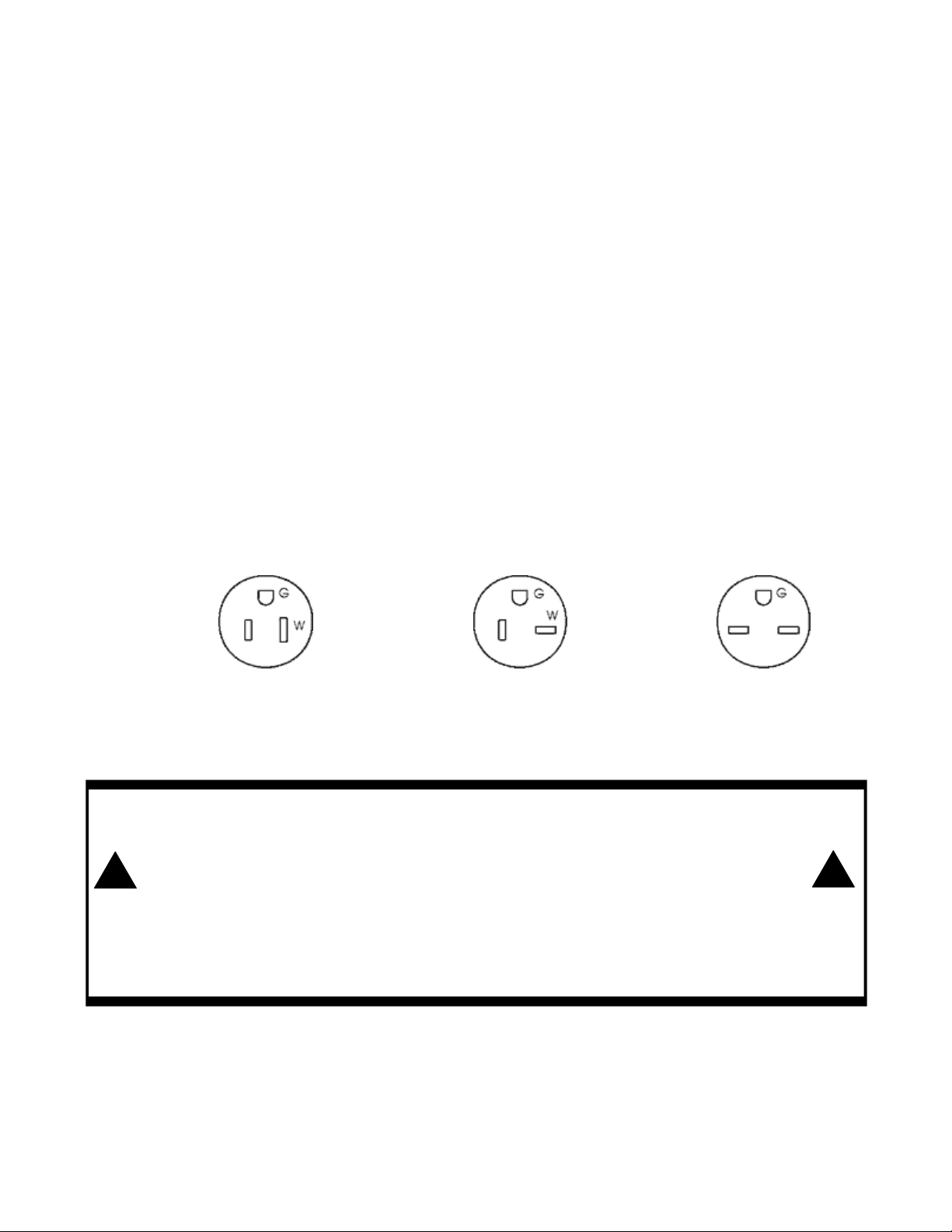
Cordset Configuration:
HDDi/HDDiS/HDXi-1-120 USES NEMA 5-15P HDDi/HDDiS/HDXi -3-120 USES NEMA 5-15P
HDDi/HDDiS/HDXi -1-208 USES NEMA 6-15P HDDi/HDDiS/HDXi -3-208 USES NEMA 6-15P
HDDi/HDDiS/HDXi -1-240 USES NEMA 6-15P HDDi/HDDiS/HDXi -3-240 USES NEMA 6-15P
HDDi/HDDiS/HDXi -2-120 USES NEMA 5-15P HDXi-4-120 USES NEMA 5-20P
HDDi/HDDiS/HDXi -2-208 USES NEMA 6-15P HDXi-4-208 USES NEMA 6-15P
HDDi/HDDiS/HDXi -2-240 USES NEMA 6-15P HDXi-4-240 USES NEMA 6-15P
NEMA 5-15P NEMA 5-20P NEMA 6-15P
If the supply cord is damaged, the manufacturer or an authorized service agent or a similarly qualified person must
replace it to avoid a hazard or voiding the warranty.
WARNING: ELECTRICAL SHOCK HAZARD. FAILURE TO FOLLOW THE INSTRUCTIONS IN THIS
MANUAL COULD RESULT IN SERIOUS INJURY OR DEATH.
•
Electrical Ground is required on this appliance.
•
DO NOT modify the power supply cord plug. If it does not fit into the outlet, have the proper outlet
installed by a qualified electrician.
•
DO NOT use an extension cord with this appliance.
•
Check with a qualified electrician if you are unsure as to whether the appliance is properly grounded.
3
Page 4

120
10-3/4x28
208
10-3/4x28
240
10-3/4x28
120
20x28
208
20x28
240
20x28
120
29-1/2x28
208
29-1/2x28
240
29-1/2x28
120
11-1/4
x20-1/2
208
11-1/4
x20-1/2
240
11-1/4
x20-1/2
120
20-3/4
x20-1/2
208
20-3/4
x20-1/2
240
20-3/4
x20-1/2
120
30
x20-1/2
208
30
x20-1/2
240
30
x20-1/2
120
10-3/4x28
208
10-3/4x28
240
10-3/4x28
120
20x28
208
20x28
240
20x28
120
29-1/2x28
208
29-1/2x28
240
29-1/2x28
120
208
240
Overall Dimensions & Electrical Specifications
Model Volts, Power Amps Overall Height Overall Width Overall Depth Cutout Shipping
Number Hz Rating Counter Built-in Counter Built-in Counter Built-in Built-in Weight
HDDi-1-120
HDDi-1-208
HDDi-1-240
HDDi-2-120
HDDi-2-208
HDDi-2-240
HDDi-3-120
HDDi-3-208
HDDi-3-240
HDDiS-1-120
HDDiS-1-208
HDDiS-1-240
HDDiS-2-120
HDDiS-2-208
HDDiS-2-240
HDDiS-3-120
HDDiS-3-208
HDDiS-3-240
HDXi-1-120
HDXi-1-208
HDXi-1-240
HDXi-2-120
HDXi-2-208
HDXi-2-240
HDXi-3-120
HDXi-3-208
HDXi-3-240
HDXi-4-120*
HDXi-4-208*
HDXi-4-240*
V (Hz) Watts A in (mm) in (mm) in (mm) in (mm) lbs (kg)
(50/60)
(50/60)
(50/60)
(50/60)
(50/60)
(50/60)
(50/60)
(50/60)
(50/60)
(50/60)
(50/60)
(50/60)
(50/60)
(50/60)
(50/60)
(50/60)
(50/60)
(50/60)
(50/60)
(50/60)
(50/60)
(50/60)
(50/60)
(50/60)
(50/60)
(50/60)
(50/60)
(50/60)
(50/60)
(50/60)
450 3.75 14-7/8 (378) 10-3/8 (263) 27-3/4 (704) 27-3/4 (704) 21 (534) 20-5/8 (524)
450 2.16 14-7/8 (378) 10-3/8 (263) 27-3/4 (704) 27-3/4 (704) 21 (534) 20-5/8 (524)
450 1.88 14-7/8 (378) 10-3/8 (263) 27-3/4 (704) 27-3/4 (704) 21 (534) 20-5/8 (524)
900 7.50 24-1/4 (616) 19-3/4 (501) 27-3/4 (704) 27-3/4 (704) 21 (534) 20-5/8 (524)
900 4.33 24-1/4 (616) 19-3/4 (501) 27-3/4 (704) 27-3/4 (704) 21 (534) 20-5/8 (524)
900 3.75 24-1/4 (616) 19-3/4 (501) 27-3/4 (704) 27-3/4 (704) 21 (534) 20-5/8 (524)
1350 11.25 33-5/8 (852) 29-1/4 (740) 27-3/4 (704) 27-3/4 (704) 21 (534) 20-5/8 (524)
1350 6.49 33-5/8 (852) 29-1/4 (740) 27-3/4 (704) 27-3/4 (704) 21 (534) 20-5/8 (524)
1350 5.63 33-5/8 (852) 29-1/4 (740) 27-3/4 (704) 27-3/4 (704) 21 (534) 20-5/8 (524)
450 3.75 14-7/8 (378) 11-1/16 (281) 20-1/4 (515) 20-1/4 (515) 29 (737) 28-5/8 (727)
450 2.16 14-7/8 (378) 11-1/16 (281) 20-1/4 (515) 20-1/4 (515) 29 (737) 28-5/8 (727)
450 1.88 14-7/8 (378) 11-1/16 (281) 20-1/4 (515) 20-1/4 (515) 29 (737) 28-5/8 (727)
900 7.50 24-1/4 (616) 20-7/16 (519) 20-1/4 (515) 20-1/4 (515) 29 (737) 28-5/8 (727)
900 4.33 24-1/4 (616) 20-7/16 (519) 20-1/4 (515) 20-1/4 (515) 29 (737) 28-5/8 (727)
900 3.75 24-1/4 (616) 20-7/16 (519) 20-1/4 (515) 20-1/4 (515) 29 (737) 28-5/8 (727)
1350 11.25 33-5/8 (852) 29-13/16 (757) 20-1/4 (515) 20-1/4 (515) 29 (737) 28-5/8 (727)
1350 6.49 33-5/8 (852) 29-13/16 (757) 20-1/4 (515) 20-1/4 (515) 29 (737) 28-5/8 (727)
1350 5.63 33-5/8 (852) 29-13/16 (757) 20-1/4 (515) 20-1/4 (515) 29 (737) 28-5/8 (727)
450 3.75 14-7/8 (378) 10-3/8 (263) 27-3/4 (704) 27-3/4 (704) 21 (534) 20-5/8 (524)
450 2.16 14-7/8 (378) 10-3/8 (263) 27-3/4 (704) 27-3/4 (704) 21 (534) 20-5/8 (524)
450 1.88 14-7/8 (378) 10-3/8 (263) 27-3/4 (704) 27-3/4 (704) 21 (534) 20-5/8 (524)
900 7.50 24-1/4 (616) 19-3/4 (501) 27-3/4 (704) 27-3/4 (704) 21 (534) 20-5/8 (524)
900 4.33 24-1/4 (616) 19-3/4 (501) 27-3/4 (704) 27-3/4 (704) 21 (534) 20-5/8 (524)
900 3.75 24-1/4 (616) 19-3/4 (501) 27-3/4 (704) 27-3/4 (704) 21 (534) 20-5/8 (524)
1350 11.25 33-5/8 (852) 29-1/4 (740) 27-3/4 (704) 27-3/4 (704) 21 (534) 20-5/8 (524)
1350 6.49 33-5/8 (852) 29-1/4 (740) 27-3/4 (704) 27-3/4 (704) 21 (534) 20-5/8 (524)
1350 5.63 33-5/8 (852) 29-1/4 (740) 27-3/4 (704) 27-3/4 (704) 21 (534) 20-5/8 (524)
1800 15.00 45 (1092) N/A 27-3/4 (704) N/A 21 (534) N/A N/A 275 (125)
1800 8.65 45 (1092) N/A 27-3/4 (704) N/A 21 (534) N/A N/A 275 (125)
1800 7.50 45 (1092) N/A 27-3/4 (704) N/A 21 (534) N/A N/A 275 (125)
(273x711)
(273x711)
(273x711)
(508x711)
(508x711)
(508x711)
(749x711)
(749x711)
(749x711)
(286x521)
(286x521)
(286x521)
(527x521)
(527x521)
(527x521)
(762x521)
(762x521)
(762x521)
(273x711)
(273x711)
(273x711)
(508x711)
(508x711)
(508x711)
(749x711)
(749x711)
(749x711)
125 (57)
125 (57)
125 (57))
175 (79)
175 (79)
175 (79)
225 (102)
225 (102)
225 (102)
125 (57)
125 (57)
125 (57))
175 (79)
175 (79)
175 (79)
225 (102)
225 (102)
225 (102)
125 (57)
125 (57)
125 (57))
175 (79)
175 (79)
175 (79)
225 (102)
225 (102)
225 (102)
*MODELS COME STANDARD WITH 6” LEGS
4
Page 5
4. OPERATION
TEMPERATURE
1. Set thermostat control to 190°F and preheat each drawer for 30 minutes.
2. Place food product directly in stainless steel drawer pans or use any combination of full or fractional pans up to
6” (152mm) deep.
3. Set front vent to desired position for maintaining food product moisture.
4. Perforated pans may be used with damp towel or small amount of hot water in the drawer pan to prevent food
“dry out”.
CAUTION: Use no more than 1 quart (1 liter) for wet operation.
5. If too much moisture accumulates around drawer front or vent, reduce temperature setting or move vent to “dry”
position.
PRODUCT TEMPERATURE SETTING VENT
PRODUCT
Rolls, Bread 160°-180°F (71°-82° C) Moist
Vegetables 160°-180°F (71°-82° C) Moist
Meats 160°-180°F (71°-82° C) Moist
NOTE: Temperature and vent settings will require adjustment according to type and quantity of food, and number of
times drawer is opened during operation.
SETTING
VENT
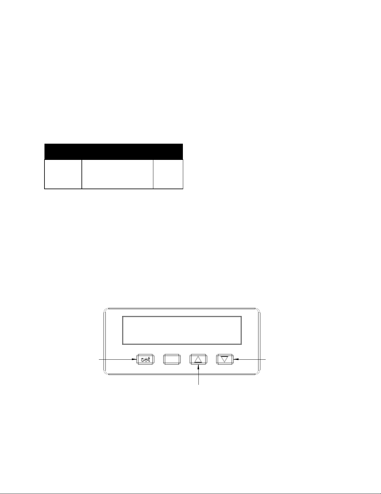
Digital Controller Operation (HDXi models only)
With unit plugged in and the rocker switch in the “ON” position, the digital controller will come on. When the controller
is on, the minimum set point value is preset to 100°F and the maximum set point is 300°F. To obtain the desired set
point, push the set key and release. You have two seconds to adjust the set temperature. Press the up or down
key to your desired setting. After setting desired temperature, release up or down key and press the set key. The
controller display should return to the measured temperature of the unit.
SET ARROW KEY
DOWN ARROW KEY
UP ARROW KEY
5
Page 6

5. CLEANING
General Cleaning Instructions:
1. NEVER clean any electrical unit by immersing it in water. Turn off before surface cleaning.
2. Always clean equipment thoroughly before first use. Clean unit daily. Use warm, soapy water. Mild cleansers
and PLASTIC scouring pads may be used to remove baked-on food and water scale.
3. Turn off electrical units before cleaning or servicing. All service should be performed by an APW authorized
service agency.
Daily Cleaning:
1. Follow General Cleaning instructions (above).
2. Remove any inset pans and drawer pans. Wash thoroughly in the sink or dishwasher.
3. Remove drawer: Remove pans and pan inserts. Extend drawer and lift up on the front to clear the drawer stop.
Lower drawer and lift over front cabinet bearing.
6. TROUBLESHOOTING GUIDE
Always ask and check the following:
1. Is the unit connected to a live power source of the proper voltage?
2. Check the circuit breaker.
3. Is power switch “ON” (HDXi models only)
4. Is the thermostat set to a temperature?
5. Is the Pilot light glowing?
6. Check the rating label. Is the unit connected to the correct power source?
6
Page 7

7. WIRING DIAGRAMS
HDDi/HDDiS WIRING DIAGRAMS
NOTE: Wire #’s 5 & 6 are not used in HDDi/HDDiS-1. Wire #’s 9 &10 are only used in HDDi/HDDiS-3
7
Page 8

8
Page 9

2
1
25
24
23
12
13
10
11
11
10
28
27
26
21
6
20
18
19
31
30
9
32
8
7
4
5
22
29
17
14
16
15
3
9
Page 10

PARTS LIST(QTY’S)
1
2
2
1
2
2
1
2
2
1
2
2
1
2
2
1
2
2
ITEM PN DESCRIPTION
1 70504805 HEATING ELEMENT, 120V 1 2 3 1 2 3
70504806 HEATING ELEMENT, 208V 1 2 3 1 2 3
70504807 HEATING ELEMENT, 240V 1 2 3 1 2 3
2 33936 TOP COVER 1 1 1 1 1 1 1 1 1 1 1 1 1 1 1 1 1 1
3 33973 OUTER SIDE PANEL 2 2 2 2 2 2
33934 OUTER SIDE PANEL 2 2 2 2 2 2
33990 OUTER SIDE PANEL 2 2 2 2 2 2
4 33976 CONTROL PANEL 1 1 1
33952 CONTROL PANEL 1 1 1
33993 CONTROL PANEL 1 1 1
70502096 CONTROL PANEL 1 1 1
70502097 CONTROL PANEL 1 1 1
70502098 CONTROL PANEL 1 1 1
5 58269 CONTROL DECAL 1 1 1
58270 CONTROL DECAL 1 1 1
58271 CONTROL DECAL 1 1 1
58273 CONTROL DECAL 1 1 1
58274 CONTROL DECAL 1 1 1
58275 CONTROL DECAL 1 1 1
6 69145 THERMOMETER 1 1 1 2 2 2 3 3 3
70101034
70101035
70101026
7 69121 THERMOSTAT 1 1 1 2 2 2 3 3 3
8 56508 KNOB 1 1 1 2 2 2 3 3 3
9 1509600 PILOT LIGHT 1 1 1 2 2 2 3 3 3
10 33858 DRAWER SLIDE ROLLER 6 6 6 12 12 12 18 18 18 6 6 6 12 12 12 18
11 89013 MACHINE SCREW 6 6 6 12 12 12 18 18 18 6 6 6 12 12 12 18
12 8353200 RIVNUT 8 8 8 16 16 16 24 24 24 8 8 8 16 16 16 24
13 8945500 LOOP CLAMP S/S 1 1 1 2 2 2 3 3 3 1 1 1 2 2 2 3 3 3
14 30203 TERMINAL BLOCK 1 1 1 1 1 1 1 1 1 1 1 1 1 1 1 1 1 1
15 60113 INSULATION 21X19X1 4 4 4 6 6 6 9 9 9 4 4 4 6 6 6 9 9 9
16 70502086 LEG SUPPORT BASE 4 4 4 6 6 6 9 9 9 4 4 4 6 6 6 9 9 9
DIGITAL CONTROLLER
120V 1 2 3
DIGITAL CONTROLLER
240V 1 1 2 2 3 3
TEMPERATURE PROBE
(120V/240V) 1 1 1 2 2 2 3 3 3
HDDi-1 HDDi-2 HDDi-3 HDXi-1 HDXi-2 HDXi-3
2
0
4
2
0
4
2
0
4
2
0
4
2
0
4
2
0
8
0
0
8
0
0
8
0
0
8
0
0
8
0
0
0
8
18 1
18 1
24 2
4
0
8
8
4
10
Page 11

PARTS LIST(QTY’S)
1
2
2
1
2
2
1
2
2
1
2
2
1
2
2
1
2
2
ITEM PN DESCRIPTION
17 87327
0-999-000
0-999-002
18 1532500 CORDSET 1 1 1 1 1 1
85645 CORDSET 1 1 1 1 1 1 1 1 1 1 1 1
19 89101 STRAIN RELEIF 1 1 1 1 1 1 1 1 1 1 1 1 1 1 1 1 1 1
20 70502092 OUTER BACK PANEL 1 1 1 1 1 1
70502082 OUTER BACK PANEL 1 1 1 1 1 1
70502094 OUTER BACK PANEL 1 1 1 1 1 1
21 33930 TOP BRACE ASSY 1 1 1 1 1 1 1 1 1 1 1 1 1 1 1 1 1 1
22 33975 RIGHT SIDE BRACE 1 1 1 1 1 1
33951 RIGHT SIDE BRACE 1 1 1 1 1 1
33992 RIGHT SIDE BRACE 1 1 1 1 1 1
23 70502072
24 70502073
25 70502077 STANDARD PAN 12X20 1 1 1 2 2 2 3 3 3 1 1 1 2 2 2 3 3 3
26 88987 SCREW, 1/4-20X3/4" 2 2 2 4 4 4 6 6 6 2 2 2 4 4 4 6 6 6
27 70502042 FLAT ROLLER BEARING 2 2 2 4 4 4 6 6 6 2 2 2 4 4 4 6 6 6
28 70502070
29 55611
30 8164100 SCREW, 10-24X1" 2 2 2 4 4 4 6 6 6 2 2 2 4 4 4 6 6 6
31 89070
32 70502060
N/A 70502045 WIRE SET 1 1 1 1 1 1
N/A 70502047 WIRE SET 1 1 1 1 1 1
N/A 70502049 WIRE SET 1 1 1 1 1 1
N/A 70503000 MANUAL 1 1 1 1 1 1 1 1 1 1 1 1 1 1 1 1 1 1
LEG, STAINLESS 6"
(OPTIONAL) 4 4 4 4 4 4 4 4 4 4 4 4 4 4 4 4 4 4
CASTER, 3"
(OPTIONALKIT OF 4) 1 1 1 1 1 1 1 1 1 1 1 1 1 1 1 1 1 1
CASTER, 5"
(OPTIONAL KIT OF 4) 1 1 1 1 1 1 1 1 1 1 1 1 1 1 1 1 1 1
RIGHT SIDE DRAWER
SLIDE 1 1 1 2 2 2 3 3 3 1 1 1 2 2 2 3 3 3
LEFT SIDE DRAWER
SLIDE 1 1 1 2 2 2 3 3 3 1 1 1 2 2 2 3 3 3
CENTER PAN SUPPORT
ASSY 1 1 1 2 2 2 3 3 3 1 1 1 2 2 2 3 3 3
HANDLE (ALSO NEED
30&31) 1 1 1 2 2 2 3 3 3 1 1 1 2 2 2 3 3 3
WASHER, #10 INTERNAL
TEETH 2 2 2 4 4 4 6 6 6 2 2 2 4 4 4 6 6 6
DRAWER ASSY
(INCLUDES 25-31) 1 1 1 2 2 2 3 3 3 1 1 1 2 2 2 3 3 3
HDDi-1 HDDi-2 HDDi-3 HDXi-1 HDXi-2 HDXi-3
2
0
4
2
0
4
2
0
4
2
0
4
2
0
4
2
0
8
0
0
8
0
0
8
0
0
8
0
0
8
0
0
0
8
4
0
11
Page 12

PARTS LIST(QTY’S)
ITEM PN DESCRIPTION
1 54114 HEATING ELEMENT, 120V 1 2 3 1 2 3
54115 HEATING ELEMENT, 208V 1 2 3 1 2 3
54116 HEATING ELEMENT, 240V 1 2 3 1 2 3
2 70501039 TOP COVER 1 1 1 1 1 1 1 1 1 1 1 1 1 1 1 1 1 1
3 70501043 OUTER SIDE PANEL 2 2 2 2 2 2
70501017 OUTER SIDE PANEL 2 2 2 2 2 2
70501049 OUTER SIDE PANEL 2 2 2 2 2 2
4 33976 CONTROL PANEL 1 1 1
33952 CONTROL PANEL 1 1 1
33993 CONTROL PANEL 1 1 1
70502096 CONTROL PANEL 1 1 1
70502097 CONTROL PANEL 1 1 1
70502098 CONTROL PANEL 1 1 1
5 58269 CONTROL DECAL 1 1 1
58270 CONTROL DECAL 1 1 1
58271 CONTROL DECAL 1 1 1
58273 CONTROL DECAL 1 1 1
58274 CONTROL DECAL 1 1 1
58275 CONTROL DECAL 1 1 1
6 69145 THERMOMETER 1 1 1 2 2 2 3 3 3
70101034
70101035
70101026
7 69121 THERMOSTAT 1 1 1 2 2 2 3 3 3
8 56508 KNOB 1 1 1 2 2 2 3 3 3
9 1509600 PILOT LIGHT 1 1 1 2 2 2 3 3 3
10 33858 DRAWER SLIDE ROLLER 6 6 6 12 12 12 18 18 18 6 6 6 12 12 12 18 18 18
11 89013 MACHINE SCREW 6 6 6 12 12 12 18 18 18 6 6 6 12 12 12 18 18 18
12 8353200 RIVNUT 8 8 8 16 16 16 24 24 24 8 8 8 16 16 16 24 24 24
13 8945500 LOOP CLAMP S/S 1 1 1 2 2 2 3 3 3 1 1 1 2 2 2 3 3 3
14 30203 TERMINAL BLOCK 1 1 1 1 1 1 1 1 1 1 1 1 1 1 1 1 1 1
15 60113 INSULATION 21X19X1 4 4 4 6 6 6 9 9 9 4 4 4 6 6 6 9 9 9
16 70501034 LEG SUPPORT BASE 1 1 1 1 1 1 1 1 1 1 1 1 1 1 1 1 1 1
DIGITAL CONTROLLER
120V 1 2 3
DIGITAL CONTROLLER
240V 1 1 2 2 3 3
TEMPERATURE PROBE
(120V/240V) 1 1 1 2 2 2 3 3 3
HDDiS-1 HDDiS-2 HDDiS-3 HDXiS-1 HDXiS-2 HDXiS-3
1
2
2
1
2
2
1
2
2
1
2
2
1
2
2
1
2
0
4
2
0
4
2
0
4
2
0
4
2
0
0
8
0
0
8
0
0
8
0
0
8
0
0
4
8
0
2
2
0
0
8
2
4
0
12
Page 13

PARTS LIST(QYT’S)
ITEM PN DESCRIPTION
HDDiS-1 HDDiS-2 HDDiS-3 HDXiS-1 HDXiS-2 HDXiS-3
1
2
2
1
2
2
1
2
2
1
2
2
1
2
2
1
2
0
4
2
0
4
2
0
4
2
0
4
2
0
0
8
0
0
8
0
0
8
0
0
8
0
0
4
8
0
2
2
0
0
8
2
4
0
17 86295 LEG, BLACK 4” 4 4 4 4 4 4 4 4 4 4 4 4 4 4 4 4 4 4
87327
0-999-000
0-999-002
18 1532500 CORDSET 1 1 1 1 1 1
85645 CORDSET 1 1 1 1 1 1 1 1 1 1 1 1
19 89101 STRAIN RELEIF 1 1 1 1 1 1 1 1 1 1 1 1 1 1 1 1 1 1
20 70501047 OUTER BACK PANEL 1 1 1 1 1 1
70501027 OUTER BACK PANEL 1 1 1 1 1 1
70501055 OUTER BACK PANEL 1 1 1 1 1 1
21 70501057 TOP BRACE ASSY 1 1 1 1 1 1 1 1 1 1 1 1 1 1 1 1 1 1
22 33975 RIGHT SIDE BRACE 1 1 1 1 1 1
33951 RIGHT SIDE BRACE 1 1 1 1 1 1
33992 RIGHT SIDE BRACE 1 1 1 1 1 1
23 70502072
24 70502073
25 70502077 STANDARD PAN 12X20 1 1 1 2 2 2 3 3 3 1 1 1 2 2 2 3 3 3
26 88987 SCREW, 1/4-20X3/4" 2 2 2 4 4 4 6 6 6 2 2 2 4 4 4 6 6 6
27 70502042 FLAT ROLLER BEARING 2 2 2 4 4 4 6 6 6 2 2 2 4 4 4 6 6 6
28 70501076
29 55613
30 8164100 SCREW, 10-24X1" 2 2 2 4 4 4 6 6 6 2 2 2 4 4 4 6 6 6
31 89070
32 70503200
N/A 70502045 WIRE SET 1 1 1 1 1 1
N/A 70502047 WIRE SET 1 1 1 1 1 1
N/A 70502049 WIRE SET 1 1 1 1 1 1
N/A 70503000 MANUAL 1 1 1 1 1 1 1 1 1 1 1 1 1 1 1 1 1 1
LEG, STAINLESS 6"
(OPTIONAL) 4 4 4 4 4 4 4 4 4 4 4 4 4 4 4 4 4 4
CASTER, 3" (OPTIONAL
KIT OF 4) 1 1 1 1 1 1 1 1 1 1 1 1 1 1 1 1 1 1
CASTER, 5" (OPTIONAL
KIT OF 4) 1 1 1 1 1 1 1 1 1 1 1 1 1 1 1 1 1 1
RIGHT SIDE DRAWER
SLIDE 1 1 1 2 2 2 3 3 3 1 1 1 2 2 2 3 3 3
LEFT SIDE DRAWER
SLIDE 1 1 1 2 2 2 3 3 3 1 1 1 2 2 2 3 3 3
CENTER PAN SUPPORT
ASSY 1 1 1 2 2 2 3 3 3 1 1 1 2 2 2 3 3 3
HANDLE (ALSO NEED
30&31) 1 1 1 2 2 2 3 3 3 1 1 1 2 2 2 3 3 3
WASHER, #10 INTERNAL
TEETH 2 2 2 4 4 4 6 6 6 2 2 2 4 4 4 6 6 6
DRAWER ASSY
(INCLUDES 25-31) 1 1 1 2 2 2 3 3 3 1 1 1 2 2 2 3 3 3
13
Page 14

2
1
12
21
23 24
13
25
31
30
11
10
28
10
11
26
27
1
29
16
19
6
7
9
8
22
4
5
14
15
20
3
14
Page 15

1
2
2
1
2
2
1
2
2
1
2
2
1
2
2
1
2
2
PARTS LIST(QTY’S)
ITEM PN DESCRIPTION
1 70504805 HEATING ELEMENT, 120V 1 2 3 1 2 3
70504806 HEATING ELEMENT, 208V 1 2 3 1 2 3
70504807 HEATING ELEMENT, 240V 1 2 3 1 2 3
2 70501039 TOP COVER 1 1 1 1 1 1 1 1 1 1 1 1 1 1 1 1 1 1
3 70501043 OUTER SIDE PANEL 2 2 2 2 2 2
70501017 OUTER SIDE PANEL 2 2 2 2 2 2
70501049 OUTER SIDE PANEL 2 2 2 2 2 2
4 33976 CONTROL PANEL 1 1 1
33952 CONTROL PANEL 1 1 1
33993 CONTROL PANEL 1 1 1
70502096 CONTROL PANEL 1 1 1
70502097 CONTROL PANEL 1 1 1
70502098 CONTROL PANEL 1 1 1
5 58269 CONTROL DECAL 1 1 1
58270 CONTROL DECAL 1 1 1
58271 CONTROL DECAL 1 1 1
58273 CONTROL DECAL 1 1 1
58274 CONTROL DECAL 1 1 1
58275 CONTROL DECAL 1 1 1
6 69145 THERMOMETER 1 1 1 2 2 2 3 3 3
70101034 DIGITAL CONTROLLER 120V 1 2 3
70101035 DIGITAL CONTROLLER 240V 1 1 2 2 3 3
70101026
7 69121 THERMOSTAT 1 1 1 2 2 2 3 3 3
8 56508 KNOB 1 1 1 2 2 2 3 3 3
9 1509600 PILOT LIGHT 1 1 1 2 2 2 3 3 3
10 33858 DRAWER SLIDE ROLLER 6 6 6 12 12 12 18 18 18 6 6 6 12 12 12 18 18 18
11 89013 MACHINE SCREW 6 6 6 12 12 12 18 18 18 6 6 6 12 12 12 18 18 18
12 8353200 RIVNUT 8 8 8 16 16 16 24 24 24 8 8 8 16 16 16 24 24 24
13 8945500 LOOP CLAMP S/S 1 1 1 2 2 2 3 3 3 1 1 1 2 2 2 3 3 3
14 30203 TERMINAL BLOCK 1 1 1 1 1 1 1 1 1 1 1 1 1 1 1 1 1 1
15 60113 INSULATION 21X19X1 4 4 4 6 6 6 9 9 9 4 4 4 6 6 6 9 9 9
16 33982 FRONT PLATE 1 1 1
TEMPERATURE PROBE
(120V/240V) 1 1 1 2 2 2 3 3 3
33963 FRONT PLATE
33999 FRONT PLATE
HDDi-1
BUILT-IN
2
0
0
8
4
0
HDDi-2
BUILT-IN
2
0
0
8
1 1 1
4
0
HDDi-3
BUILT-IN
2
0
0
8
1 1 1
4
0
HDXi-1
BUILT-IN
2
0
0
8
1 1 1
4
0
HDXi-2
BUILT-IN
2
0
0
8
1 1 1
4
0
HDXi-3
BUILT-IN
2
0
0
8
1 1 1
4
0
15
Page 16

PARTS LIST(QTY’S)
HDDi
-
1
HDDi
-
2
HDDi
-
3
HDXi
-
1
HDXi
-
2
HDXi
-
3
1
2
2
1
2
2
1
2
2
1
2
2
1
2
2
1
2
2
ITEM PN DESCRIPTION
19 84559 HOLE PLUG 1 1 1 1 1 1 1 1 1 1 1 1 1 1 1 1 1 1
20 70501047 OUTER BACK PANEL 1 1 1 1 1 1
70501027 OUTER BACK PANEL 1 1 1 1 1 1
70501055 OUTER BACK PANEL 1 1 1 1 1 1
21 70501057 TOP BRACE ASSY 1 1 1 1 1 1 1 1 1 1 1 1 1 1 1 1 1 1
22 33975 RIGHT SIDE BRACE 1 1 1 1 1 1
33951 RIGHT SIDE BRACE 1 1 1 1 1 1
33992 RIGHT SIDE BRACE 1 1 1 1 1 1
23 70501018 RIGHT SIDE DRAWER SLIDE 1 1 1 2 2 2 3 3 3 1 1 1 2 2 2 3 3 3
24 70501019 LEFT SIDE DRAWER SLIDE 1 1 1 2 2 2 3 3 3 1 1 1 2 2 2 3 3 3
25 70502077 STANDARD PAN 12X20 1 1 1 2 2 2 3 3 3 1 1 1 2 2 2 3 3 3
26 88987 SCREW, 1/4-20X3/4" 2 2 2 4 4 4 6 6 6 2 2 2 4 4 4 6 6 6
27 70502042 FLAT ROLLER BEARING 2 2 2 4 4 4 6 6 6 2 2 2 4 4 4 6 6 6
28 70501076 CENTER PAN SUPPORT ASSY 1 1 1 2 2 2 3 3 3 1 1 1 2 2 2 3 3 3
29 55613 HANDLE (ALSO NEED 30&31) 1 1 1 2 2 2 3 3 3 1 1 1 2 2 2 3 3 3
30 8164100 SCREW, 10-24X1" 2 2 2 4 4 4 6 6 6 2 2 2 4 4 4 6 6 6
31 89070
32 70503200
N/A 70502045 WIRE SET 1 1 1 1 1 1
N/A 70502047 WIRE SET 1 1 1 1 1 1
N/A 70502049 WIRE SET 1 1 1 1 1 1
N/A 70503000 MANUAL 1 1 1 1 1 1 1 1 1 1 1 1 1 1 1 1 1 1
WASHER, #10 INTERNAL
TEETH 2 2 2 4 4 4 6 6 6 2 2 2 4 4 4 6 6 6
DRAWER ASSY (INCLUDES 25-
31) 1 1 1 2 2 2 3 3 3 1 1 1 2 2 2 3 3 3
BUILT-IN
2
0
0
8
4
0
BUILT-IN
2
0
BUILT-IN
0
4
2
8
0
0
BUILT-IN
0
4
8
2
0
0
0
4
2
8
0
0
BUILT-IN
0
8
4
0
BUILT-IN
2
0
0
8
4
0
16
Page 17

PARTS LIST(QTY’S)
HDDiS
-
1
HDDiS
-
2
HDDiS
-
3
HDXiS
-
1
HDXiS
-
2
HDXiS
-
3
1
2
2
1
2
1
2
2
ITEM PN DESCRIPTION
1 54114 HEATING ELEMENT, 120V 1 2 3 1 2 3
54115 HEATING ELEMENT, 208V 1 2 3 1 2 3
54116 HEATING ELEMENT, 240V 1 2 3 1 2 3
2 70501079 TOP COVER 1 1 1 1 1 1 1 1 1 1 1 1 1 1 1 1 1 1
3
4 33976 CONTROL PANEL 1 1 1
5 58269 CONTROL DECAL 1 1 1
6 69145 THERMOMETER 1 1 1 2 2 2 3 3 3
7 69121 THERMOSTAT 1 1 1 2 2 2 3 3 3
8 56508 KNOB 1 1 1 2 2 2 3 3 3
9 1509600 PILOT LIGHT 1 1 1 2 2 2 3 3 3
10 33858 DRAWER SLIDE ROLLER 6 6 6 12 12 12 18 18 18 6 6 6 12 12 12 18 18 18
11 89013 MACHINE SCREW 6 6 6 12 12 12 18 18 18 6 6 6 12 12 12 18 18 18
12 8353200 RIVNUT 8 8 8 16 16 16 24 24 24 8 8 8 16 16 16 24 24 24
13 8945500 LOOP CLAMP S/S 1 1 1 2 2 2 3 3 3 1 1 1 2 2 2 3 3 3
14 30203 TERMINAL BLOCK 1 1 1 1 1 1 1 1 1 1 1 1 1 1 1 1 1 1
15 60113 INSULATION 21X19X1 4 4 4 6 6 6 9 9 9 4 4 4 6 6 6 9 9 9
16 70501078 FRONT PLATE 1 1 1
70501081
70501082
70501091
70501092
70501086
70501087
33952 CONTROL PANEL 1 1 1
33993 CONTROL PANEL 1 1 1
70502096 CONTROL PANEL 1 1 1
70502097 CONTROL PANEL 1 1 1
70502098 CONTROL PANEL 1 1 1
58270 CONTROL DECAL 1 1 1
58271 CONTROL DECAL 1 1 1
58273 CONTROL DECAL 1 1 1
58274 CONTROL DECAL 1 1 1
58275 CONTROL DECAL 1 1 1
70101034 DIGITAL CONTROLLER 120V 1 2 3
70101035 DIGITAL CONTROLLER 240V 1 1 2 2 3 3
70101026
70501088 FRONT PLATE
70501084 FRONT PLATE
OUTER RIGHT SIDE PANEL
OUTER LEFT SIDE PANEL
OUTER RIGHT SIDE PANEL
OUTER LEFT SIDE PANEL
OUTER RIGHT SIDE PANEL
OUTER LEFT SIDE PANEL
TEMPERATURE PROBE
(120V/240V) 1 1 1 2 2 2 3 3 3
BUILT-IN
2
0
0
8
2 2 2 2 2 2
2 2 2 2 2 2
2 2 2 2 2 2
4
0
BUILT-IN
2
0
1 1 1
08 24
BUILT-IN
20 208 240 120 208 240 120 208 240 12
0
1 1 1
1 1 1
BUILT-IN
BUILT-IN
1 1 1
BUILT-IN
0
0
8
1 1 1
4
0
17
Page 18

PARTS LIST(QYT’S)
HDDiS
-
1
HDDiS
-
2
HDDiS
-
3
HDXiS
-
1
HDXiS
-
2
HDXiS
-
3
1
2
2
1
2
1
2
2
ITEM PN DESCRIPTION
19 84559 HOLE PLUG
20 70501080 OUTER BACK PANEL
70501090 OUTER BACK PANEL
70501085 OUTER BACK PANEL
21 70501057 TOP BRACE ASSY
22 33975 RIGHT SIDE BRACE
33951 RIGHT SIDE BRACE
33992 RIGHT SIDE BRACE
23 70502072 RIGHT SIDE DRAWER SLIDE
24 70502073 LEFT SIDE DRAWER SLIDE
25 70502077 STANDARD PAN 12X20
26 88987 SCREW, 1/4-20X3/4"
27 70502042 FLAT ROLLER BEARING
28 70501076 CENTER PAN SUPPORT ASSY
29 55613 HANDLE (ALSO NEED 30&31)
30 8164100 SCREW, 10-24X1"
31 89070
32 70503200
N/A 70502045 WIRE SET
N/A 70502047 WIRE SET
N/A 70502049 WIRE SET
N/A 70503000 MANUAL
WASHER, #10 INTERNAL
TEETH
DRAWER ASSY (INCLUDES 25-
31)
BUILT-IN
2
0
0
8
1 1 1 1 1 1 1 1 1 1 1 1 1 1 1 1 1 1
1 1 1 1 1 1
1 1 1 1 1 1
1 1 1 1 1 1
1 1 1 1 1 1 1 1 1 1 1 1 1 1 1 1 1 1
1 1 1 1 1 1
1 1 1 1 1 1
1 1 1 1 1 1
1 1 1 2 2 2 3 3 3 1 1 1 2 2 2 3 3 3
1 1 1 2 2 2 3 3 3 1 1 1 2 2 2 3 3 3
1 1 1 2 2 2 3 3 3 1 1 1 2 2 2 3 3 3
2 2 2 4 4 4 6 6 6 2 2 2 4 4 4 6 6 6
2 2 2 4 4 4 6 6 6 2 2 2 4 4 4 6 6 6
1 1 1 2 2 2 3 3 3 1 1 1 2 2 2 3 3 3
1 1 1 2 2 2 3 3 3 1 1 1 2 2 2 3 3 3
2 2 2 4 4 4 6 6 6 2 2 2 4 4 4 6 6 6
2 2 2 4 4 4 6 6 6 2 2 2 4 4 4 6 6 6
1 1 1 2 2 2 3 3 3 1 1 1 2 2 2 3 3 3
1 1 1 1 1 1
1 1 1 1 1 1
1 1 1 1 1 1
1 1 1 1 1 1 1 1 1 1 1 1 1 1 1 1 1 1
4
0
BUILT-IN
2
08 24
0
BUILT-IN
20 208 240 120 208 240 120 208 240 12
0
BUILT-IN
BUILT-IN
BUILT-IN
0
0
8
4
0
18
Page 19

IMPORTANT FOR FUTURE REFERENCE
Please complete this information and retain this manual for the life of the equipment. For
Warranty Service and/or Parts, this information is required.
______________ ______________ _______________
Model Number Serial Number Date Purchased
Notes:_____________________________________________________________
__________________________________________________________________
__________________________________________________________________
__________________________________________________________________
__________________________________________________________________
__________________________________________________________________
__________________________________________________________________
__________________________________________________________________
__________________________________________________________________
__________________________________________________________________
__________________________________________________________________
__________________________________________________________________
__________________________________________________________________
__________________________________________________________________
__________________________________________________________________
__________________________________________________________________
__________________________________________________________________
__________________________________________________________________
__________________________________________________________________
__________________________________________________________________
__________________________________________________________________
__________________________________________________________________
__________________________________________________________________
19
Page 20

20
 Loading...