

Page 1
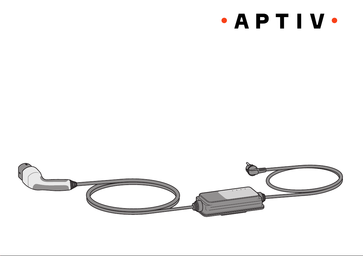
User Manual
Electric Vehicle Charging Equipment IC-CPD
(In-Cable Control- and Protection Device)
POWER
CHARGING
TEMPERATURE
FAULT
Online User Manual IC-CPD / 35383918
Version 1.0 / 1906
Page 2

User Manual – Electric Vehicle Charging Equipment IC-CPD
Contents
Electric Vehicle Charging Equipment IC-CPD
1. General information .............................. 2
2. IC-CPD charging equipment overview ... 3
3. Warnings, symbols
and pictograms used ............................ 4
4. Safety instructions ................................ 6
5. Main features ....................................... 9
6. User benefits and features .................. 10
7. Available vehicle charging inlets
and vehicle connectors ........................ 11
8. Available power cables for
industrial sockets ............................... 12
9. Available power cables for
domestic sockets ............................... 12
10. Front display of the ICCB control box .. 14
11. Operation ........................................... 15
12. Troubleshooting .................................. 15
13. Fault rectification ................................ 15
14. Back label of the ICCB control box ....... 17
15. Maintenance and care ........................ 18
16. Product modifications ......................... 18
17. Disposal ............................................ 19
2
18. Warranty information .......................... 19
19. Specifications..................................... 20
20. Service .............................................. 21
21. Spacer (optional) ................................ 21
Abbreviations
BEV ..............................Battery Electric Vehicle
PRCD-S .............................. Portable switching
..................................Residual Current Device
EVSE ............Electric Vehicle Supply Equipment
FCC .......Federal Communications Commission
ICCB ...............................In-Cable Control Box
IC-CPD ..............................................In-Cable
..........................Control and Protection Device
LED .......... Light-Emitting Diode (indicator light)
PHEV ................. Plug-in Hybrid Electric Vehicle
1. General information
This User Manual is based on the latest product
information at the time of publication. APTIV
reserves the right to modify the product without
prior notice. Any changes or modifications made
to the product may result in loss of warranty if
they are not carried out by an approved service
workshop.
If you have any questions regarding the use of
this product, please contact your service representative. For the customer service organisation
responsible for your area please refer to the
manual of your vehicle!
Company information
Aptiv Services Deutschland GmbH
Am Technologiepark 1
D-42119 Wuppertal
GERMANY
Internet: www.aptiv.com
Version 1.0 / 1906
Page 3
User Manual – Electric Vehicle Charging Equipment IC-CPD
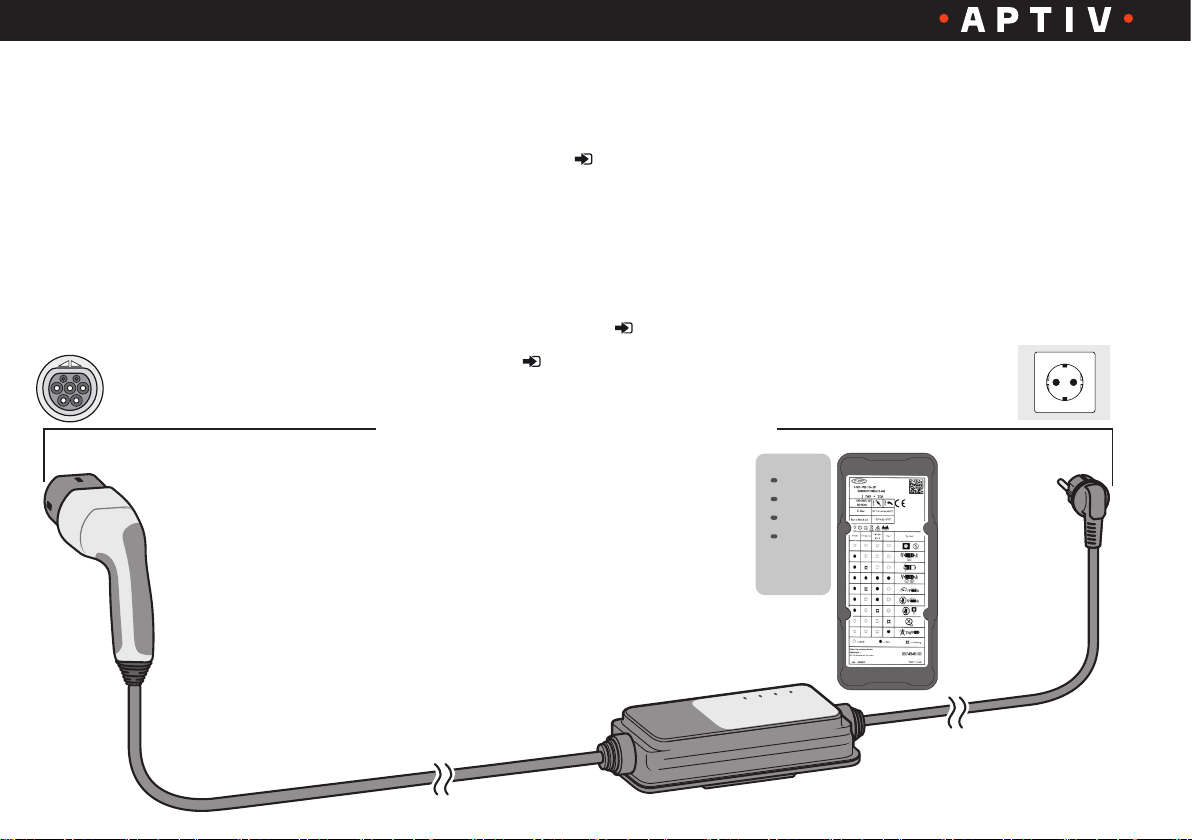
2. IC-CPD Overview
For the definition of the individual system
components refer to the overview below.
A
B
Vehicle charging inlet
A
Vehicle connector ( page 11)
B
Control box (ICCB)
C
AC power cable
D
Power plug
E
Grid socket
F
Front display with LEDs ( page 14)
G
Back label ( page 17)
H
IC-CPD
(In-Cable Control- and Protection Device)
G H
C
FAULT
POWER
CHARGING
TEMPERATURE
FAULT
TEMPERATURE
CHARGING
F
E
D
POWER
Version 1.0 / 1906
3
Page 4
User Manual – Electric Vehicle Charging Equipment IC-CPD
3. Warnings, symbols and pictograms used
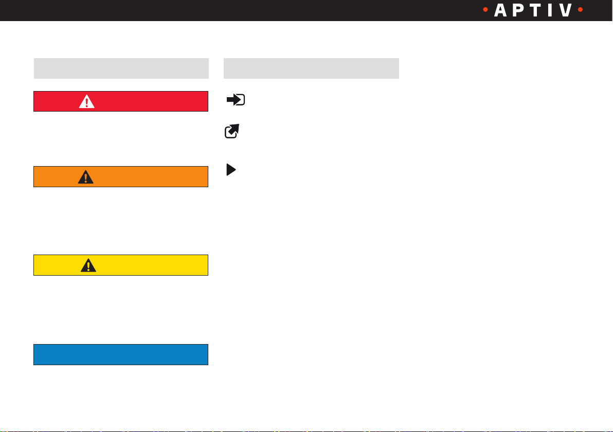
Warnings
DANGER
Indicates imminent danger.
Failure to follow this instruction will
result in death or serious injury.
WARNING
Indicates a possibly impending danger.
Failure to follow this instruction can
result in death or serious injury.
CAUTION
Indicates a dangerous situation.
Failure to follow this instruction can
result in light or minor injury.
NOTE
Symbols
Reference to other sections in the
User Manual
Reference to other documents
or instructions
Handling instruction
Draws attention to a situation which,
if not avoided, could result in material
damage.
4
Version 1.0 / 1906
Page 5
User Manual – Electric Vehicle Charging Equipment IC-CPD
3. Used warnings, symbols and pictograms
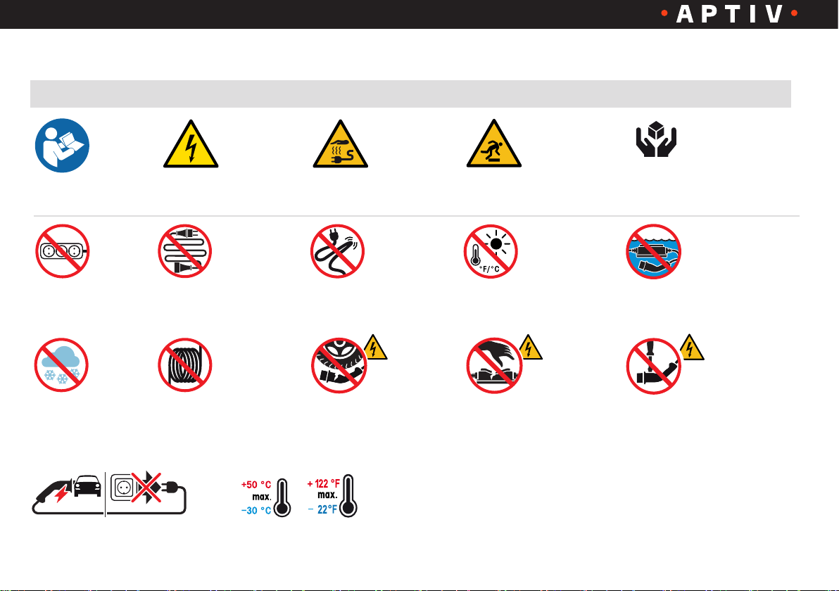
Pictograms
Instruction:
Follow instructions
Warning:
Electric voltage
Warning:
Hot surface
Warning:
Obstacles on the ground
Handle with care
Instruction:
Handle charging device with care
Prohibition:
No multiple sockets
Prohibition:
No extension cables
and adapters
Prohibition:
No contact with snow
or ice
Prohibition:
Do not use
the charging equipment
with coiled up cables
Prohibition:
Do not unplug the power plug
during the charging process
Prohibition:
Do not kink the cable
Prohibition:
Do not run over plug,
control box and cables
Temperature range for start-up
Prohibition:
No direct sunlight,
no direct cover
Prohibition:
Do not use the IC-CPD
if it is damaged
Prohibition: Do not immerse in
water, do not expose to a direct jet
of water or splash water
Prohibition: Do not carry out
repairs on the IC-CPD
and do not open it
Version 1.0 / 1906
5
Page 6
User Manual – Electric Vehicle Charging Equipment IC-CPD
4. Safety instructions
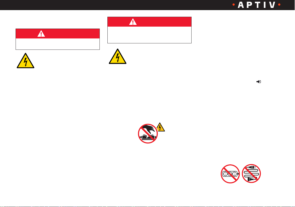
DANGER
Electric shock or fire hazards
Incorrectly installed sockets
can lead to electric shock
or fire when charging the
high-voltage battery via the vehicle
charging inlet.
• Operate the IC-CPD charging
equipment in properly grounded
power networks only
• The grid socket used for charging
must be connected to a protected
circuit that complies with local laws
and standards
• The socket must be protected by a
functioning residual current-operated
circuit-breaker (RCCB)
• Comply with the safety instructions
in the installation manual and in the
vehicle manual
DANGER
Electric shock, short circuit, fire,
explosion
Using a damaged or
faulty charging cable or a
damaged or faulty socket,
improper use of the IC-CPD charging
equipment or failure to comply with the
precautions can cause short-circuits,
electrocution, explosions, fire and burns.
• Do not use the IC-CPD charging
device if it is damaged and/or soiled.
Check cable and connector for
damage and soiling before using
them
• Do not use a socket that is worn-out
or damaged. The power plug must
be firmly seated in a socket in
accordance with all local codes and
ordinances
The operation of the IC-CPD charging
equipment connected to a worn or
damaged socket can result in serious
injury or fire!
• Do not remove the cover and do
not open the housing. The device
contains no parts that could be
serviced by the user. Leave any
servicing tasks to qualified personnel
(see service information page 21)
• Do not touch any parts inside the
vehicle connector
• Do not apply any overvoltage to
the IC-CPD charging equipment!
For the socket voltages suitable
for the device please refer to the
specification on the back label
• Do not use extension cords, cable
drums, multiple sockets, (travel)
adapters, timers, etc.
Version 1.0 / 1906
6
Page 7
User Manual – Electric Vehicle Charging Equipment IC-CPD
4. Safety instructions
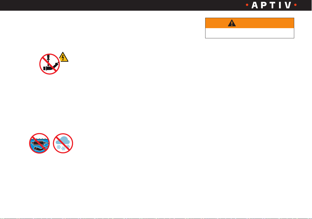
• Do not perform any modifications or
repair tasks to electrical components
and do not open the device
• Do not touch the contacts on the
vehicle charging inlet and the IC-CPD
charging equipment
• Keep sockets, plug connection and
the IC-CPD charging equipment free
of moisture, water, snow, ice and other
liquids. Never immerse in water
• Disconnect the IC-CPD charging
device from the socket during a
thunderstorm
• Do not insert any objects in the
vehicle charging inlet or in the
IC-CPD charging equipment
• Clean the IC-CPD charging
equipment only if the control unit is
completely disconnected from the
power grid and from the vehicle. Use
a dry cloth for cleaning
• The IC-CPD charging equipment
should not be operated by persons
under the influence of drugs, alcohol
or medications
• The IC-CPD charging equipment
should not be operated by persons
who are not familiar with its use or
who have not read the User Manual
• Keep the IC-CPD charging equipment
away from persons with disabilities
and children who cannot assess the
hazards involved with its handling
• While performing an unattended
charging process unauthorized
persons (e.g. playing children) should
not have access to the IC-CPD
charging equipment
WARNING
Explosion or fire hazards
In order to determine whether the
vehicle is equipped with a charging
inlet, please refer to the vehicle manual.
Components of the IC-CPD charging
equipment can cause sparks and ignite
flammable or explosive vapors.
• During charging ensure that the
control box is located at least 20
inches (50 cm) above ground
to reduce the risk of explosions,
particularly in garages
• Do not use the charging and control
device in potentially explosive
ambients
• This device is intended only for
charging vehicles, which do not
require ventilation during the
charging process
Version 1.0 / 1906
7
Page 8
User Manual – Electric Vehicle Charging Equipment IC-CPD
4. Safety instructions
NOTE
The charging and control device
could be damaged
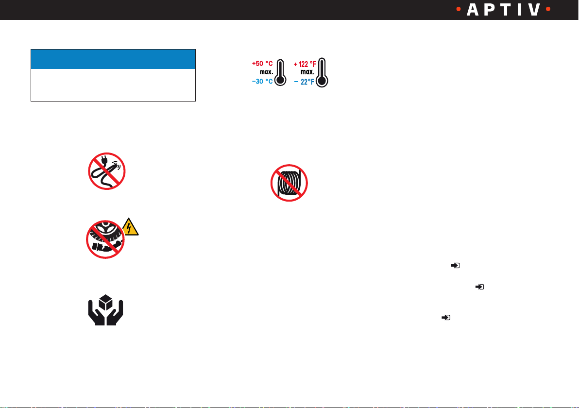
• Do not slide the IC-CPD charging
equipment over sharp edges
• Avoid kinking the charging cable
• Do not run over plug, control box or
cables
• Do not exert any unusual mechanical
strain on the IC-CPD
Handle with care
• Do not operate the IC-CPD charging
equipment outside the permissible
ambient temperature range from
-22 °F (-30 °C) to 122 °F (+50 °C).
8
Lower or higher temperatures can
damage the device
• Do not attempt to connect notmatching vehicle connectors and
charging inlets
• Do not use the IC-CPD charging
equipment with coiled cables
Intended use
• Operate the charging cable directly
connected to a fixed grid socket only
• It is prohibited to use the charging
cable for vehicles from other
manufacturers
• Improper use can result in mal-
functions and damage to property. The
charging equipment with integrated
in-cable control and protection device
(IC-CPD) from APTIV is a mobile
charging device for electrical vehicles
(EVSE) with a mains connection for
charging of battery-powered electric
vehicles (BEV) and plug-in hybrid
electric vehicles (PHEV)
The safe, user-friendly mobile IC-CPD
(mode 2) allows the owners of electric
vehicles to connect and charge their
vehicles virtually everywhere to 100 V
- 240 V AC current grids depending on
the regional current grid and the device
version.
This system consists of three separate
components that together offer a solid
and reliable method of charging an
electric vehicle.
1. AC power cable (plug type according
to region) ( pages 3 and 12)
2. Control box ICCB ( pages 3 and 13)
3. Vehicle connector type (according to
region) ( pages 3 and 11)
Version 1.0 / 1906
Page 9
User Manual – Electric Vehicle Charging Equipment IC-CPD
5. Main features
• Levels of safety for the user, the
electric vehicle and the IC-CPD
charging equipment
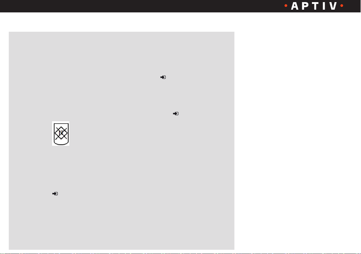
• Ground monitoring
(model-dependent)
• Your version is equipped with
ground monitoring if it displays
the following symbol on its back
label
• Versions with ground monitoring
do not work in power grids without
protective conductor
• Four LEDs (detailed description of the
front display page 14)
• Charging circuit breaker (PRCD-S) with
automatic re-closure of the circuit
• Push-button controlled lock for a
secure connection between the
IC-CPD charging equipment and the
vehicle connector (for type 1 and
GB/T only, page 11)
• The IC-CPD charging equipment
is for indoor and outdoor use. For
further information, please refer to
the back label ( page 17)
Version 1.0 / 1906
9
Page 10
User Manual – Electric Vehicle Charging Equipment IC-CPD
CHARGING
TEMPERATURE
POWER
FAULT
6. User benefits and features
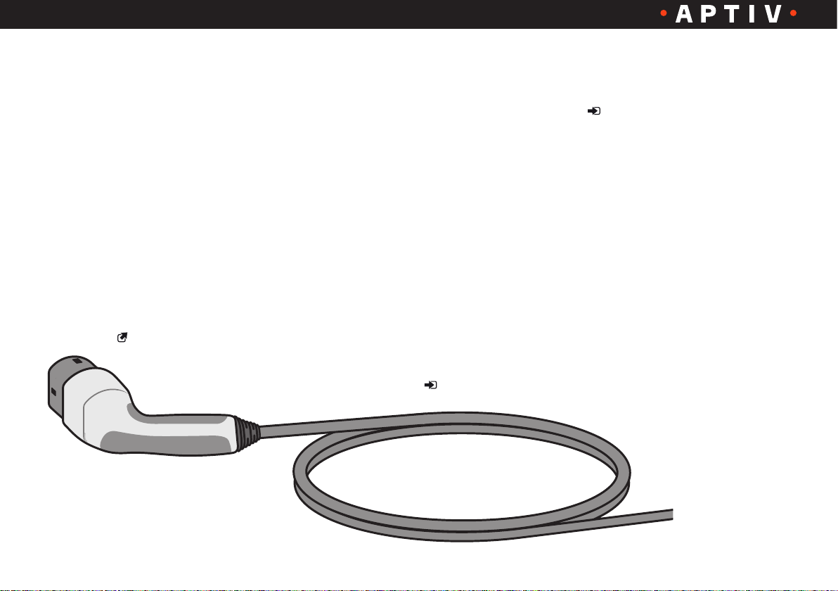
This IC-CPD charging equipment allows you to
charge your battery-powered electric vehicle
(BEV) or plug-in hybrid electric vehicle (PHEV)
without any additional device. The user-friendly
plug system makes the vehicle connector fit
directly into the charging inlet of the vehicle and
the existing electrical infrastructure.
The IC-CPD charging equipment provides a
standard grounded power connection to residential
building sockets from 100 V to 240 V 50/60 Hz
(depending on the model variant) and a charging
current of 6 A up to 16 A according to the
specifications on the back label of the control box
of your device.
Vehicle cable:
• IEC 62196-1 Plugs, socket-outlets,
vehicle connectors and vehicle
inlets – Conductive charging of
electric vehicles –
Part 1: General requirements
• IEC 62196-2 Plugs, socket-outlets,
vehicle connectors and vehicle
inlets – Conductive charging of
electric vehicles –
Part 2: Dimensional compatibility
and interchangeability requirements
for a.c. pin and contact-tube
accessories
• Microswitch-based proximity switch
(exclusively for vehicle connectors
type 1 and GB/T page 11)
• Knurled knob for easy, slip-proof
locking control (exclusively for
vehicle connector type 1 and GB/T
page 11)
• Ergonomic rubber grip for optimal
support
• When the vehicle charging inlet
and grid socket are properly
connected, all terminal interfaces
and terminals are fully protected
against contact
• Temperature monitoring
• The IC-CPD continually monitors
the temperature inside the
power plug, so that any
over-heating under certain
conditions of the power plug
is avoided
Version 1.0 / 1906
10
Page 11
User Manual – Electric Vehicle Charging Equipment IC-CPD
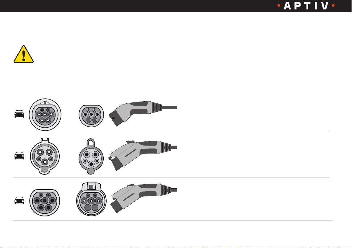
7. Available vehicle charging inlets and vehicle connectors
Depending on the country-specific equipment, different vehicle charging inlets and vehicle connectors
are provided.
Use only the charging equipment approved for your country.
Vehicle
charging inlet
Vehicle
connector
Type
IEC 62196-2
Type 2
IEC 62196-2/SAE-J1772-2009
Type 1
GB/T 20234.2
Type GB/T
Available
charging inlets
• Two 3 mm contact sleeves for
control contact
• Two 6 mm contact sleeves for line
• A 6 mm contact sleeve for
grounding contact
• Two 1.5 mm contact sleeves for
control contact
• Two 3.6 mm contact sleeves for
line
• A 2.8 mm contact sleeve for
grounding contact
• Two 3 mm contact pins for control
contact
• Two 6 mm contact pins for line
• A 6 mm contact sleeve for
grounding contact
Version 1.0 / 1906
11
Page 12

User Manual – Electric Vehicle Charging Equipment IC-CPD
8. Available power cables for
industrial sockets
For charging at optimum charging speed, use
only the following power plugs. The maximum
charging capacity is up to 3.6 kW (depending
on the power grid/house connection and onboard charger).
Take account of page 20 „Specifications“.
Comply with the instructions in the vehicle
manual.
Socket
Connector
Type
IEC 60309-2
CEE 16/3
Camping type
JIS C 8303 (JWDS-0033)
9. Power cables for electrical
domestic sockets are available
in different country’s versions
Socket
Connector
Type
NEMA-5-15
Type B
CEE 7/7
Type E/Type F „SchuKo“
BS 1363
Type G
AS 3112
Type I
GB 2099.1
Type I
SEV 1011
Type J
Socket
Connector
AFSNIT 107-2 D1
Type K
CEI 23-50
Type L
SANS 164-1
Type M
NBR 14136
Type N
TIS 166-2549
Type O
IRAM 2073
Type I
CNS 690
Type B
Type
Version 1.0 / 1906
12
Page 13
User Manual – Electric Vehicle Charging Equipment IC-CPD
CHARGING
TEMPERATURE
POWER
FAULT
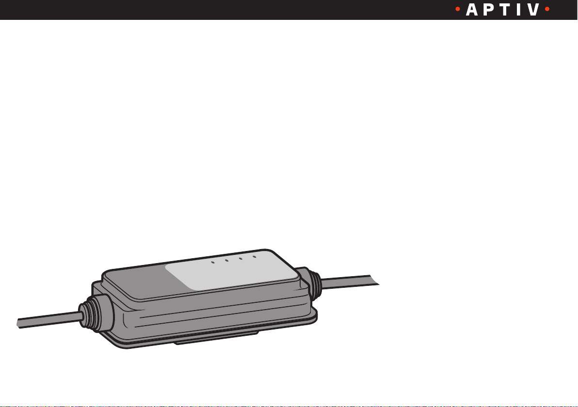
ICCB:
• IEC 61851-1 Electric vehicle
conductive charging system –
Part 1: General requirements
• Ground monitoring
• Depending on the equipment, the
ICCB measures the protective
conductor resistance and stops
the charging process if the
measured value is too high
• Charging circuit breaker
PRCD-S (protection device against
electric shock)
• Detects fault currents and disables
the charging process
• A self-test that avoids the need
of a monthly review after power-up
and before each charging cycle
• Charging circuit breaker ON/OFF
• Permits the charging process to be
resumed after certain errors and a
waiting period of 5 minutes
• If the error has been corrected, no
user intervention is required
• Temperature monitoring
• The ICCB continually monitors the
temperature inside the box and
thus prevents overheating under
certain conditions
Version 1.0 / 1906
13
Page 14
User Manual – Electric Vehicle Charging Equipment IC-CPD
10. Front display of the ICCB
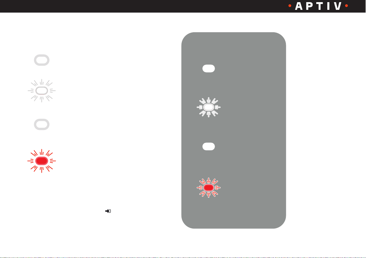
The front panel of the IC-CPD is equipped with four
indicator lights:
1. POWER is illuminated:
Electricity from the grid is on and the
IC-CPD is ready for use
2. CHARGING flashing:
A flashing light indicates that energy is
delivered to the vehicle
3. TEMPERATURE is illuminated:
The internal temperature exceeds a
certain value
4. FAULT flashing red:
Shows a failure of the charging system
According to the operating mode, the IC-CPD charging
equipment emits different combinations of continuously
illuminated and/or flashing LEDs.
(For additional explanations, see page 17)
POWER
CHARGING
TEMPERATURE
FAULT
Version 1.0 / 1906
14
Page 15
User Manual – Electric Vehicle Charging Equipment IC-CPD
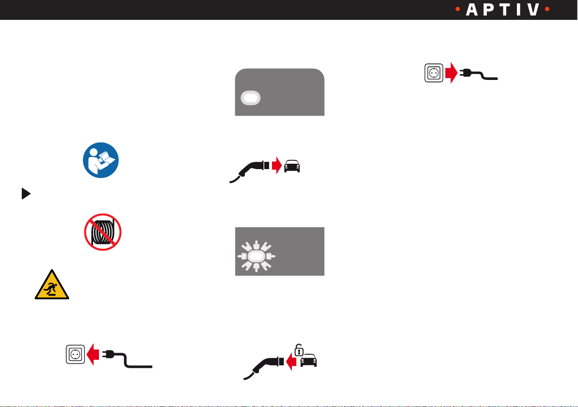
11. Operation
For the operation of your IC-CPD
charging equipment, observe the
following instructions:
1. Read fully and understand the vehicle
manual and the instructions for the
IC-CPD charging equipment
Completely uncoil the cable of the
IC-CPD charging equipment
2. Ensure that the cables are
routed correctly over their
entire length, in order to
avoid stumbling
3. Insert the power plug into the socket
4. Wait until the Power LED lights up
continuously
POWER
POWER
5. Insert the vehicle connector
into the vehicle‘s charging inlet
6. The charging process begins auto matically
CHARGING
7. To interrupt the charging process,
unlock the vehicle charging inlet
and remove the vehicle connector
8. Remove the power plug from the
socket
9. Keep the IC-CPD charging
equipment in a safe place
Version 1.0 / 1906
15
Page 16
User Manual – Electric Vehicle Charging Equipment IC-CPD
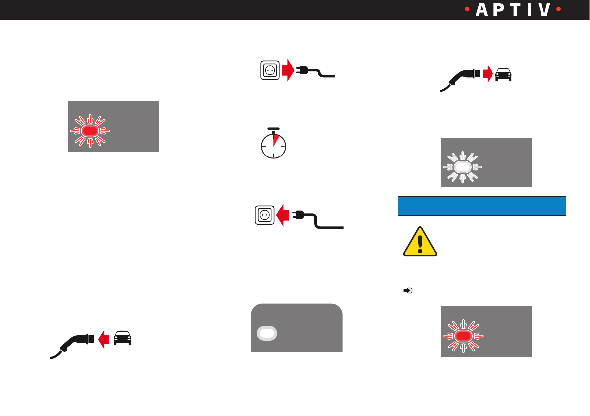
12. Troubleshooting
1. Display: The FAULT LED flashes three
times, followed by a short break
FAULT
2. Check the socket or protect the
IC-CPD charging equipment from
direct sunlight or elevated
temperatures
13. Fault rectification
Proceed as follows:
1. Remove the vehicle connector from
the vehicle’s charging inlet
2. Remove the power plug from the
socket
3. Wait for approximately 5 seconds
5 sec
4. Insert the power plug carefully into
the socket
5. Wait until the Power LED lights up
continuously
POWER
POWER
6. Insert the vehicle connector into
the vehicle‘s charging inlet
7. The charging process restarts auto matically
CHARGING
NOTE
If the FAULT LED flashes
continuously red after or
during the charging process,
do not use the device;
contact your regional customer service
( page 21).
FAULT
Version 1.0 / 1906
16
Page 17
User Manual – Electric Vehicle Charging Equipment IC-CPD
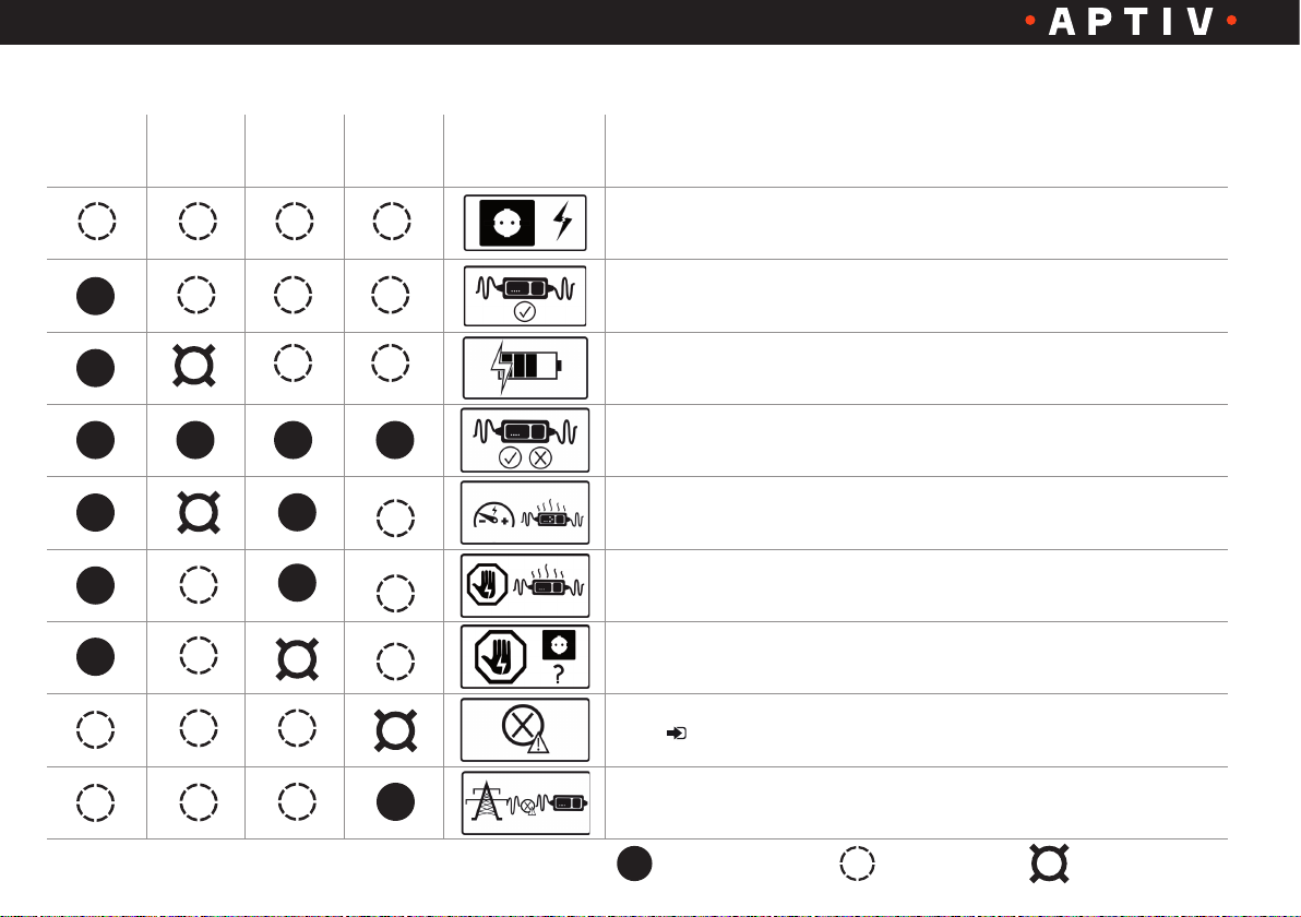
14. Back label of the ICCB
POWER CHARGING
TEMPERA-
TURE
FAULT Pictogram Description
No electrical power supply detected
IC-CPD ready for use
Charging
The IC-CPD is currently running a self-test
Slow charging process due to increased temperature. The charging process
can take longer
Charging interruption due to increased temperature of the ICCB. Check the
grid socket or protect the IC-CPD charging equipment from direct sunlight
Interruption of the charging process due to increased temperature in the
power plug
Fault ( page 16)
The power grid is down or cannot be used for charging with this device.
The grid socket must be checked by a trained electrician
= ON = OFF = Flashing
Version 1.0 / 1906
17
Page 18
User Manual – Electric Vehicle Charging Equipment IC-CPD
15. Maintenance and care 16. Product change
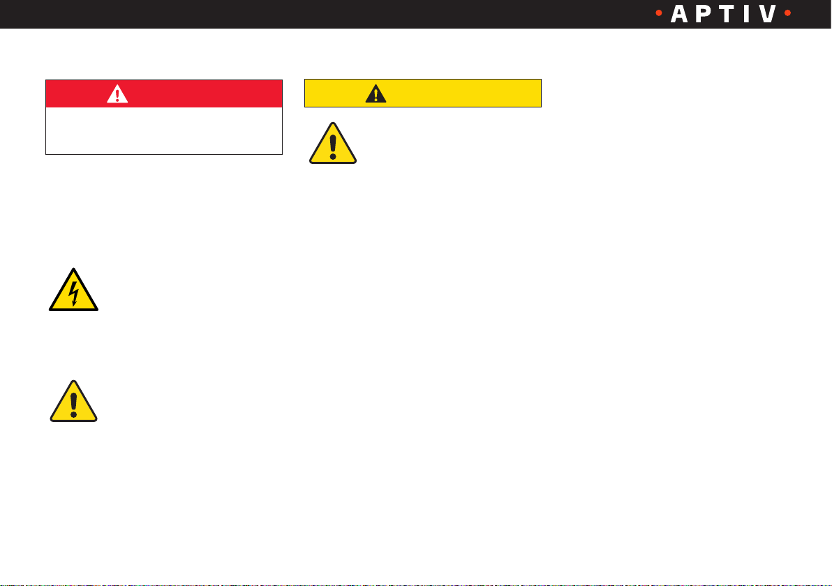
DANGER
Electric shock, short circuit, fire,
explosion
Warning! To reduce hazards of electric
shock and damage to the device, clean
the plugs and the housing with utmost
caution.
Clean the IC-CPD charging
equipment with a dry cloth.
Do not use any cleaning
agents or flammable solvents, such as
alcohol or benzene.
Cleaning or any other
contact with chemicals can
damage the device and is
prohibited.
CAUTION!
Any changes or modifications
made to the product, which
are not carried out by an
authorized service workshop, result in
the loss of FCC Compliance and are
prohibited.
Version 1.0 / 1906
18
Page 19

User Manual – Electric Vehicle Charging Equipment IC-CPD
17. Disposal
The disposal of
decommissioned devices
must be in accordance
with the applicable
country- specific and
regional laws and guidelines. Equipment and batteries must never be
disposed of with domestic waste.
• Decommissioned equipment must be placed
in a collection facility for electronic waste or
disposed of via your dealer
• Dispose of the packing material in the
respective collection bins for cardboard,
paper and plastics
18. Warranty information
APTIV ensures that this product will be free
from defects in material and workmanship as
well as from design errors for a period of one
(1) year from the original purchase date. In
the event a product is found to be defective in
material, manufacturing or construction within
this warranty period, APTIV will, at its discretion, repair or replace the defective product.
Repair parts and/or replacement products can
be replaced at the discretion of APTIV with
either new or reconditioned products. This
limited warranty does not include the repair of
damage due to improper installation, incorrect
connection of peripherals, external electrical
interference, accident, disaster, misuse or
any changes made in the product that are
not approved in writing by APTIV. Any service
repairs, which are not covered by the limited
warranty, shall be performed at the rates, terms
and conditions applicable at the time of the
repair.
Any other express or implied warranties in
relation to this product, including the warranty
of general suitability and fitness for a particular
purpose, are hereby excluded. In some
countries, the exclusion of implied warranties is
not permitted, so the above disclaimer may not
apply in your situation.
If the product does not conform to the above warranty, your exclusive remedy shall be
the replacement or repair of the defective
product, as fully described above. Under no
circumstances shall APTIV, a sales or service
representative or the parent company be held
liable to the customer or any third party for any
damages that exceed the purchase price of
the product. This limitation applies to damages
of any kind, including any direct or indirect
damages, lost profits, lost savings or special,
incidental damages, punitive or consequential
damages, whether due to a breach of contract,
tort or any other means, or if such damages
are based on the use or improper use of
the product, even if APTIV or an authorized
representative or dealer of APTIV has been
advised by third parties about the possibility of
such damages or any other claim.
In some countries, the exclusion of incidental
or consequential damages is not permitted
for some products, so the above limitation or
exclusion may not apply to you.
This warranty gives you specific legal rights,
and you may have other rights, which vary from
country to country.
Please contact your customer service staff.
For your responsible customer service,
please refer to the manual of your vehicle!
Version 1.0 / 1906
19
Page 20

User Manual – Electric Vehicle Charging Equipment IC-CPD
19. Specifications
Electrical specification
Power:
Rated current:
Rated voltage:
Grid frequency:
Overvoltage category:
Rated short-time withstand current:
Residual current device:
Protection class:
IP protection class:
Variants of the power plug:
Variants of the vehicle charging
inlets and vehicle connectors:
max. 3.6 kW
(depending on model and version)
max. 16 A
(depending on the model variant)
1-phase: 100 - 240 V ~
(depending on the model variant)
50 Hz - 60 Hz
II
< 10 kA rms
Type A
II
IP67 (ICCB)
Page 12
Available power plugs for
industrial sockets
Available power plugs for
domestic sockets
Page 11
Available vehicle charging inlets
and vehicle connectors
Dimensions and weight
Dimensions of the IC-CPD charger:
Weight of the IC-CPD charger:
Environmental conditions
Operating temperature:
Storage temperature:
Humidity:
Altitude:
Guidelines and standards
Directives of the European Union:
Standards:
Approx. 3.74 in. x 8.66 in. x 2.32 in.
(95 mm x 220 mm x 59 mm) (wx hxd)
Approx. 5.18 lbs. (2.35 kg)
-22 °F to +122 °F (-30 °C to +50 °C)
-40 °F to +158 °F (-40 °C to +70 °C)
Up to 95%, non-condensing
max. 16,404 ft (5,000 m)
above sea level
• 2014/35/EU, 2014/30/EU
• 2011/65/EU
This IC-CPD charging equipment
meets all applicable IEC and EN
standards and regulations in the
context of national legislation, as
well as the European and international regulations. If necessary,
the respective declaration of
conformity can be made available
Version 1.0 / 1906
20
Page 21
User Manual – Electric Vehicle Charging Equipment IC-CPD
20. Service
Please contact your local dealer for assistance.
For the contact data, please refer to your
vehicle’s owner manual!
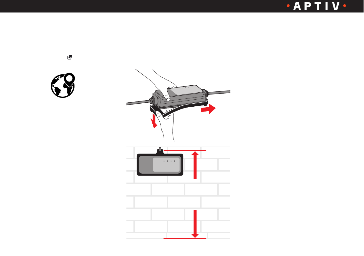
21. Optional spacer
(depending on model)
Remove the spacer when not needed:
POWER
CHARGING
TEMPERATURE
FAULT
2.
1.
TEMPERATURE
POWER
FAULT
CHARGING
max. 3.3 ft.
(max. 1m)
Version 1.0 / 1906
21
 Loading...