

Page 1
Media Air Cleaners
E
Installation Instructions
WARNING
1. High voltage may cause serious
injury from electrical shock.
Disconnect power to the
furnace/air handler before
starting installation.
2. Sharp edges may cause injury
from cuts. Use care when cutting
and handling sheet metal.
1. To prevent component failure, do not install the air cleaner on the warm
air supply or in an area where the temperature may exceed 140°F. This
may include areas above heat exchangers in downflow furnaces or above
exhaust flues in lowboy furnace cold air returns.
2. Installation must be done by a qualified heating and air conditioning
professional. Read instructions thoroughly before beginning installation.
3. Do not install air cleaner downstream of a UV light. UV lamps will cause
degradation of the filtering media.
SPECIFICATIONS
Airflow Capacity: up to 2000 CFM maximum
Replacement Media:
1210, 2210, 3210: Model 210 or 213 with SelfSeal
1310, 2310, 3210: Model 310 or 313 with SelfSeal
1410, 2410, 3410: Model 410 or 413 with SelfSeal
CAUTION
Max. Equipment Weight:
Cabinet will support 400 lb. static load
™
™
™
Air Cleaner Operating Environment:
Temperature: 0°F – 140°F
Humidity: 0-90% non-condensing
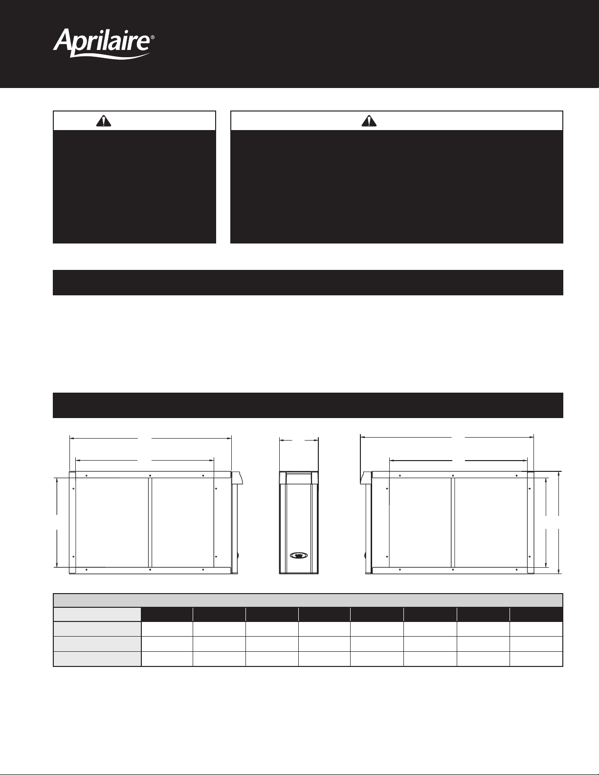
DIMENSIONS
A
Model A B C D E F G H
1210, 2210, 3210
1310, 2310, 3310
1410, 2410, 3410
B
without door
C
19-3/4 25-3/8 21-3/16 6-3/4 27-3/8 21-3/16 19-3/4 22-1/16
18-1/16 20-1/16 15-7/8 6-3/4 22-1/16 15-7/8 18-1/16 20-3/8
15-7/16 28-1/16 23-7/8 6-3/4 30-1/16 23-7/8 15-7/16 17-3/4
D
TABLE 1 – Dimensions (inches)
with door
F
G H
90-1333
Page 2
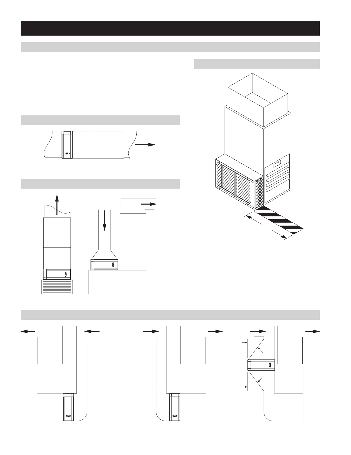
INSTALL THE AIR CLEANER CABINET
LOCATING THE AIR CLEANER
1. Leave sufficient space in front of the air cleaner for the removal of
the filtering media (see Figure 1).
2. DO NOT INSTALL DOWNSTREAM OF A UV LIGHT. UV lamps
will cause degradation of the filtering media.
3. Figures 2-4 show typical applications.
FIGURE 2 – Horizontal Installation
Airflow
90-1319
FIGURE 3 – Highboy Installation
Airflow
Airflow
FIGURE 1 – Filtering Media Clearance
90-1374
29"
FIGURE 4 – Highboy Upflow Installation
2
90-1318
Airflow AirflowAirflow
30° max
45° max
90-1320
Page 3

INSTALLATION
1. Disconnect power to the furnace or air handler at the electrical service panel.
FIGURE 5
WARNING
120 Volts may cause serious injury from electrical shock. Disconnect
power to the furnace/air handler before starting installation. Leave power
disconnected until installation is completed.
2. Remove the air cleaner door from the outer housing and pull out the filtering media.
3. If replacing an existing filter, remove the filter and thoroughly clean the blower
compartment.
4. Use screws (field supplied) to mount the outer housing to the furnace/air handler.
There is no inlet or outlet side on the outer housing (the outer housing can be mounted
on the left or right side of the furnace/air handler).
NOTE FOR UPFLOW INSTALLATIONS: Provide support under the outer housing to ensure the quality of the seals (see Figure 5).
5. Mount the return ductwork to the outer housing.
6. Seal all connections using mastic, foil tape or silicone based caulk.
7. Install the filtering media (see Figure 6).
FIGURE 6
90-1374
8. Install the door.
9. Reconnect power to the furnace or air handler at the electrical
service panel.
Expand clean filter.
Install filter with Air Flow pointing
toward Furnace or Air Handler.
Align filter in top and bottom rails
and slide into place. Reinstall door.
3
Page 4

P.O. Box 1467 • Madison, WI 53701-1467 • Phone: 800/334-6011 • Fax: 608/257-4357 • www.aprilairepartners.com
10009757 1.12
B2701229A
© 2012 Aprilaire – A division of Research Products Corporation
Printed in U.S.A.
 Loading...