

Page 1

INSTALLATION &
OPERATING MANUAL
Network Video Recorder
NVR-2018
Before trying to connect or operate this product, please read this manual completely
Page 2

Page 3

SAFETY PRECAUTIONS
All the following safety and operated instructions which will prevent harm or damage to the operator
and other persons should be read before the unit is operated.
WARNING
To reduce the risk of fire or electric shock, do not expose this appliance to rain or moisture.
Do not block ventilation openings.
Do not place anything on top of the unit that might spill or fall into it.
Do not attempt to service this unit yourself as opening or removing covers may expose you
to dangerous voltage or other hazards. Please refer all servicing to qualified service
personnel.
Do not use liquid cleaners or aerosols for cleaning.
This installation should be by a qualified service person and should conform to all local
codes.
To prevent fire or electric shock, do not overload wall outlets or extension cord.
This unit must be grounded to reduce the risk of electric shock hazard.
CAUTION
Danger of explosion if the Lithium battery (RTC Battery) is incorrectly replaced.
Danger of explosion if battery is incorrectly replaced. Replace only with the same or
equivalent type recommended by the manufacturer. Dispose of used batteries
according to the manufacturer’s instructions.
Risk of explosion if replaced by an incorrect type. Dispose of used batteries according to the
instructions.
INFORMATION
This equipment has been tested and found to comply with the limits for a Class A digital device,
pursuant to Part 15 of the FCC Rules. These limits are designed to provide reasonable
protection against harmful interference when the equipment is operated in a commercial
environment. This equipment generates, uses, and can radiate radio frequency energy and, if
not installed and used in accordance with the instruction manual, may cause harmful
interference to radio communications.
Operation of this equipment in a residential area is likely to cause harmful interference in which
case the user will be required to correct the interference at his own expense.
1
Page 4

Table Of Contents
1. PRODUCT FEATURES .................................................................................................. 4
1.1 Product Introduction ..................................................................................................................4
1.2 Product Features ........................................................................................................................4
2. DESCRIPTION OF THE FRONT/REAR VIEW............................................................... 6
2.1 Front View..................................................................................................................................6
2.2 Rear View ...................................................................................................................................9
2.3 ALARM In/Out .........................................................................................................................10
3. INSTALLATION ............................................................................................................ 11
3.1 Basic Connection .....................................................................................................................11
3.2 Hard-Disk Drive Installation ...................................................................................................13
3.3 System Information ..................................................................................................................14
3.4 Updating System Software .......................................................................................................15
4. BASIC OPERATIONS .................................................................................................. 16
4.1 Configuring Recording Settings............................................................................................... 16
4.2 Recording Operations ..............................................................................................................17
4.3 Playback Operations................................................................................................................24
4.4 Search Operations....................................................................................................................26
4.5 Backup Operations................................................................................................................... 29
4.6 Key Lock Operation ................................................................................................................. 32
5. MENU SETUP .............................................................................................................. 33
5.1 LAN CAMERA SETTING......................................................................................................... 34
5.2 REC SETTING .........................................................................................................................39
5.3 CLOCK / TIMER / SEQ SETTING ..........................................................................................41
5.4 ALARM SETTING ....................................................................................................................42
5.5 COMMUNICATION ................................................................................................................44
5.6 DISK SETTING........................................................................................................................ 46
5.7 SYSTEM SETTING................................................................................................................... 47
2
Page 5

6. RS-232 PROTOCOL .................................................................................................... 50
6.1 Setup.........................................................................................................................................50
6.2 Communication Protocol .........................................................................................................50
7. IDE HARD DISK INSTALLATION ................................................................................ 53
7.1 Built-in hard disk......................................................................................................................53
7.2 Mobile Rack .............................................................................................................................54
8. O.S.D MESSAGE ......................................................................................................... 57
9. NETWORK VIEWER AND IMAGE VIEWER................................................................ 58
9.1 The Network Viewer .................................................................................................................58
9.2 The Image Viewer..................................................................................................................... 67
10. INDEX TABLE ............................................................................................................ 68
11. NETWORK CONFIGURATION................................................................................... 69
11.1 Cable Connections .................................................................................................................69
11.2 Configure Your NVR Network Settings................................................................................... 70
11.3 TCP/IP Communication Software ..........................................................................................72
11.4 TCP/IP installation................................................................................................................. 73
11.5 TCP/IP Configuration setting.................................................................................................74
11.6 Connection Testing .................................................................................................................74
12. MICROSOFT INTERNET EXPLORER....................................................................... 76
12.1 Connecting the NVR-2018 .....................................................................................................76
12.2 Change LANCAM SETUP Setting ......................................................................................... 79
12.3 Change Record / Alarm Setting..............................................................................................80
12.4 Change Timer Record Setting ................................................................................................81
13. SPECIFICATIONS ...................................................................................................... 82
APPENDIX 1. –SCANIP................................................................................................... 83
3
Page 6

1. PRODUCT FEATURES
1.1 Product Introduction
The NVR is a storage media of digital video image, which uses hard disk drives instead of NAS
devices to store video. This storage media provides the user with the power of remote control of the
Internet. It’s an extremely stable and reliable device because it is a stand-alone system. Its local
operations are very similar to the DVR’s interface, hence if the user is familiar with the DVR s/he will
find this media to be most convenient. You don’t need to design any analog lines yourself, just use
the current existing network lines since the device is a digital one. Again, where the NAS is a passive
device, the NVR is an active one, which automatically, instantly and directly detects all events without
having to detour via the LAN Camera like the NAS.
Additionally, with the NVR you don’t have to rely on a PC to save any images, because this device
has done so already, being the best possible storage media for the LAN Camera.
1.2 Product Features
* Digital recorder for LAN the Camera.
* Maximum link-up of 8 LAN Cameras.
* Zoom in/out available for every LAN Camera.
* Compression method: MJPEG.
* Maximum 2 hard-disk drive capability. (One removable)
* Hard-disk drive hot-swapping capability.
* Pre-alarm image recording.
* Capable of backup with various known FTP server.
* Time-lapse and real-time recording.
* Refresh rate up to 30 IPS (25 IPS for PAL).
* Alarm I/O.
* Image quality selectable at 5 different levels for recording.
* Event/Timer/Alarm recording mode.
* Quick search by time, alarm, event, and recording list.
* Fast and slow playback of recorded video at various speeds.
* Single-picture playback.
* On-screen setup menu, title and system timer.
* Password protection.
* Motion detection: user can select the range and 5 levels of sensitivity of detection.
* Automatic search of all available LAN camera within the Ethernet.
* Disk-full warning and operation status LEDs.
* RS-232 communication port.
* Remote control via RS-232 and Ethernet ports
* Power interruption recovery.
4
Page 7

* High stability and reliability.
* Operation-status record log.
* Distribution of live and recorded images throughout the TCP/IP network environment.
* Powerful PC software.
* Web browser: IE.
* Audio function included.
* Built-in SD card slot for copying image to SD card.
* Supports the DHCP protocol.
5
Page 8

2. DESCRIPTION OF THE FRONT/REAR VIEW
2.1 Front View
Power Display
Save
1 3 4 5 6
Setup
CH1
CH2
CH5
CH6
CH4
CH3
CH8
CH7
Enter
Seq.
8
4
Shift
223 24
A-recSearch
T-rec
PLAY
PAUSE
STOP
REC
FWDREV
POWERDISK
7 8 9 10 11 14 13 12 15 16 17 18 19 20 21 22
Hard-disk drive compartment:
The compartment allows you to install a hard disk drive mostly for backup purposes. Make sure the
drive is well secured with the mounting screws in the mobile rack before you put the rack into the
compartment. And remember to turn on the power of the compartment by locking it.
Hard disk compartment lock:
The key lock secures a hard disk in place. Unlock the compartment before you remove the hard
disk from the slot without turning off the device.
PAU SE button:
In a playback display, press this to freeze the display. During the freeze, press to display one
frame/field of a picture at a time in the forward direction. (Illuminate green in PAUSE mode.)
PLAY button:
Press to play back a recorded video from the hard disk. (Illuminate green in PLAY mode.)
STOP button:
Press to stop playing back a recorded video or recording video into a hard disk. (Illuminate green
in STOP mode.)
REC button:
Push to start recording video into a hard disk while in the live display mode. (Illuminate red in REC
mode.)
POWER button:
Press this button for at least 3 seconds to power off. Press again to activate the device.
DISPLAY button:
Press to show the system operation status on the screen.
In the LANCAM SETTING mode, use these buttons to display the desired LAN Camera image on the
screen.
6
Page 9

Setup/Save button:
Press this to enter the setup menu. Press again to exit the setup mode.
In SD card backup mode, press to save the desired still image to SD card.
Search button:
Press to enter the search mode to access recorded video.
In the LANCAM SETTING mode, use these buttons to search for the desired LAN Camera in the
LAN.
Left / Right (CH1-CH5 / CH2-CH6 ) buttons:
In setup menu/ search mode, press these two buttons to highlight desired items in the menu setup
mode.
In the live mode, press
display. In order to display channel 5 or 6, please press Shift button while pushing
buttons respectively to see the selected channel.
In the play mode, press
small-screen display, next as a full-screen display. Similarly, in order to display channel 5 or 6 in
the play mode, press Shift button while pushing
selected channel, first as a zoom-in, small-screen display, and next in a full-screen view.
Up / Down ( CH4-CH8 / CH3-CH7 )buttons:
In setup menu/ search mode, press these two buttons to select the desired contents for
programming in the setup menu mode.
In the live mode, press
display. In order to display channel 8 or 7, please press Shift button while pushing
buttons respectively to see the selected channel.
In the play mode, press
small-screen display, next as a full-screen display. Similarly, in order to display channel 8 or 7 in
the play mode, press Shift button while pushing
selected channel, first as a zoom-in, small-screen display, and next in a full-screen view.
or buttons to select channel 1 or 2 respectively to get a full-screen
or
or buttons to see channel 1 or 2 respectively, first as a zoom -in,
or buttons respectively to see the
or buttons to select channel 4 or 3 respectively to get a full-screen
or
or buttons to see channel 4 or 3 respectively, first as a zoom -in,
or buttons respectively to see the
Enter Button:
Press to enter a selected item and save the setting in the menu setup mode.
In the live or play mode, this button enables the user to access the multiple-channel screen display.
Pressing this button repeatedly will enable a sequential display in the following order: first, a
quad-mode display of channels 1-4, and then, 5-8, and a multiple-channel display of channels 1-8,
in succession.
Shift button:
Press Shift button while pushing either the Left / Right buttons, or the Up / Down buttons, to see
any corresponding channel between channels 5-8.
Press Shift and Enter buttons simultaneously for a sequential display in the exact same order
given above. (please refer to the “NOTE” given below)
T-rec Indicator:
This indicator of the timer recording mode lights up to signal the scheduled record setting is on.
7
Page 10

A-rec Indicator:
This indicator of the alarm recording mode lights up to indicate the alarm record setting is on.
DISK Indicator:
The indicator shows the operation status of the unit’s hard-disk drives. The green light indicates the
hard-disk drive is storing or retrieving data. The red light signals the hard-disk drive is filling up. The
orange light indicates the hard-disk is retrieving at disk-full status.
Shuttle Ring:
The shuttle can be moved forward and backward for playback in either direction. Turn this left to
play a recorded video in the reverse direction at faster or slower speeds than the recorded speed.
Turn this right to play a recorded video in the forward direction at faster or slower speeds than the
recorded speed.
Jog Dial:
This dial can act in both a forward and a backward direction, as well as step by step. Turn this left
to play a recorded video in the reverse direction. Turn this right to play a recorded video in the
forward direction.
POWER Indicator:
Indicates the power status of the unit. The green light indicates the hard disk drive is
activating. The
orange light signals the hard disk drive is power stand by.
Mobile Rack Power LED:
Indicates the power status of the Mobile Rack. The green light indicates the Mobile Rack is
activating.
Mobile Rack HDD LED:
Indicates the HDD status of the Mobile Rack. The orange light indicates the HDD is storing or
retrieving data.
NOTE: Press “ Enter ” and “ Shift ” simultaneously in order to view all the channels, one by
one, in sequential single-channel succession, followed by an 8-channel display, a
quad-mode display of channels 1-4, and channels 5-8, and then a multiple-channel
viewing, after which you have this exact same sequential order of display indefinitely.
8
Page 11

2.2 Rear View
25 26 27
SD Card
RS-232
ALARM
I/O
DC12V
MONITOR AUDIO
28
29 30 31 32 33
ETHERNET
ETHERNET 10/100 Connector: This is one standard RJ-45 connector for 10/100 Mbps Ethernet
networks.
SD CARD Slot: This is used for system software updating and archiving/accessing critical images.
RS-232 Port: The RS-232 communication port functions as a connector to an external control device.
Please refer to RS-232 Protocol for more details.
MONITOR Connector: The connector provides the unit’s composite video live signal if connected to a
display device.
AUDIO OUT: This provides the unit’s audio signal to a speaker.
ALARM I/O: This is a 9-PIN D-SUB connector including GROUND, ALARM OUT, DISK FULL, and
RECORD IN for connecting with external devices. Please refer to the next section for details.
Wire Catch: The wire catch secures the power cord and keeps it in place (so that it does not droop or
hang loosely).
Ground Screw’s: The ground screw is for chassis terminal.
Plug Inlet: The inlet connects to an external power supply. Connect 12 V DC UL Listed Class 2 Power
Supply.
9
Page 12

2.3 ALARM In/Out
DISK FULL
NO CONNECTION
ALARM OUT
RECORD IN GROUND
12345
6789
NO CONNECTION
NO CONNECTION
NO CONNECTION
NO CONNECTION
THIS FIGURE IS LOOKED FROM THE REAR VIEW
1. GND: Ground Contact.
2. ALARM OUT (OUTPUT): This is an alarm output trigger. Connect this to external devices such as
5V
buzzers or lights. (
3. DISK FULL (OUTPUT): This is a disk full output trigger. Connect this to external devices such as
buzzers or lights. (
4. NO CONNECTION
5. RECORD IN (INPUT): This pin connects to a record trigger device for starting a record.
5V
0V(Active)
(
6. NO CONNECTION
7. NO CONNECTION
8. NO CONNECTION
9. NO CONNECTION
)
0V(Active)
5V
0V(Active)
)
)
10
Page 13

3. INSTALLATION
Please follow the instructions and the diagram below to set up the system.
3.1 Basic Connection
CONNECTING WITH A SINGLE CAMERA
To Video In
To Audio In
Monitor
MONITOR AUDIO
ETHERNET
CROSSOVER CABLE
SD Card
RS-232
ALARM
I/O
LAN CAMERA
DC12V
11
Page 14

LANCAM, NVR, ROUTER, CONNECTION STRUCTURE
PC
Monitor
NVR
SD Card
ISP/
INTERNET
WAN
MONITOR AUDIO
VIDEO ROUTER
LAN
(UP TO 8 LAN CAMERA)
ETHERNET
RS-232
ALARM
I/O
L1L2L3L4L5L6L7L8L9L10
DC12V
PC
LAN CAMERA
12
Page 15

3.2 Hard-Disk Drive Installation
The NVR is equipped with two compartments of hard disk drive. The unit usually comes with one
hard-disk drive installed in the compartment HD1, which is default-configured as a master. If you need a
second hard-disk drive to be installed in the compartment HD2 (Mobile), please contact your distributors
or installers for specific instructions on how to install it. Please don’t serve yourself before consulting
your installers. If there is only one hard-disk drive in the mobile compartment, please set the
USAGE
jumper-settings arrangement of installed hard-disk drives for the system (Table 3.2 A.) is shown in the
tables below.
Table 3.2 A. The jumper settings of hard disk drives in the system
Western Digital
Seagate
Maxtor
SAMSUNG
option to REC (Please refer to section 5.6) before proceed recording function. The
Location Jumper
IDE 1 Compartment HD 1 Master (Default)
IDE 2 Compartment HD 2 Master
Table 3.2 B. Compatible hard-disk drives
Manufacturer Model Capacity Rotation
WD800AB 80GB 5400 RPM
WD1200AB 120GB 5400 RPM
WD800BB 80GB 7200 RPM
WD1200BB 120GB 7200 RPM
WD1800BB 180GB 7200 RPM
WD2000BB 200GB 7200 RPM
WD2500JB 250GB 7200 RPM
ST380020A/P 80GB 5400 RPM
ST340810A/P 40GB 5400 RPM
ST320014A 20GB 5400 RPM
ST340015A 40GB 5400 RPM
ST380012ACE 80GB 5400 RPM
ST3120025ACE 120GB 5400 RPM
4A160J0-1A 160GB 5400 RPM
4R080L0-1 80GB 5400 RPM
6Y120L0-1 120GB 7200 RPM
6Y200P0-1A 200GB 7200 RPM
6Y250P0-1A 250GB 7200 RPM
SV0802N 80GB 5400 RPM
SV1203N 120GB 5400 RPM
HD2
NOTE: Hard-disk drives not shown on this list have not been tested by the engineering team
and are not recommended for use with this product. For the latest updated list on the
recommended hard disk drives, please contact your dealers or distributors.
13
Page 16

3.3 System Information
You can display system settings information as shown on
Display button . In the playback mode, the recorded video information is displayed. In the live or
recording mode, the Manual Recording information is displayed. Each sequential press of the
button
displays a different message detailed in the following example. By default, the unit displays
time, date, and an indicating bar of capacity status on a monitor as shown next.
Default display
CAM1 CAM2
CAM3 CAM4 CAM5 CAM6
CAM7 CAM8
Table 3.3 A below at any time by pressing the
Display
04-09-2003 12:48:19
Press the
display. Press the
Display button once; the NVR will display the following sample message plus the default
Display button again; the unit will not display any OSD message. Press the
button one more time to back to the default display.
Table 3.3 A. Description of Table 3.3 A
CH LANCAM IP X
1 192.168.001.250 LIVE 19 227K
2 192.168.001.020 LIVE 19 221K
3 192.168.001.030
- - -
4 192.168.001.040 OFF
5 192.168.001.050 OFF
6 192.168.001.060 OFF
7 192.168.001.070 OFF
8 192.168.001.080 OFF
IP : 192.168.001.205 DHCP:OFF NTSC
HD SIZE POS
1 20 G 39.5% R 11 HR (HD1)
2 39 G 0.0% P
04-09-2003 12:48:19
(CH): Channel
(LANCAM IP): LAN Camera IP address
(LIVE): The LAN Camera activated
(OFF): The LAN Camera inactivated
(19): The channel current display speed rate, 19 images/sec
):Disconnection; ( ):Alarm; ( ):login error;
(
):motion; ( ):Audio; ( ):Time r
(
(227K): The LAN Camera bandwidth
(LANCAM IP : 192 . 168 . 001 . 205): Setting of the Ethernet
communication,192.168.001.205
(DHCP:OFF): Only use manual setup IP address
(NTSC): NTSC system
( ): Indicate which HDD is activated
(HD): Hard disk Compartment
(SIZE 20G): The capacity of the installed hard disk
(POS): Percentage of system; R: Recording; P: Playback
11 HR (HD1): Per minute change showing the total recording
time.
X): Cannot operate at now
(
14
Page 17

3.4 Updating System Software
If the system software of the NVR-2018 needs to be upgraded, please take the following steps to safely
update it.
Important: Before carrying out the following procedures, please ensure the SD card is working
and the file of system software is intact
1. Create a directory named NVRVIDEO in the SD Card; if the directory is already existed, move to
Step2.
2. Copy the file of
MULTI.BIN to the NVRVIDEO-directory.
3. If NVR is running, please turn off NVR first.
4. Insert the SD card into the built-in SD slot of the unit.
5. Hold down the
Up and Down buttons simultaneously, and then turn on the unit.
6. Keep holding down the buttons until the NVR-2018 sounds a tone and display the message
“
XXXXXX BYTES READ” Now the NVR-2018 is updating the system software, which will take
approximately 60 seconds to process.
7. Restart the unit when the device sounds a tone twice and displays the messages “
END
” and “ PLEASE RESTART”. The process is complete.
PROGRAMMING
(If you have already followed the procedure 1~5. the unit, however, not being able to power on.
Please first check if the SD card you are using is functioning and the file is intact. And then start
procedures 1 ~ 5 all over again.)
8. Verify the version of the system software. (Please refer to section 5.7 VERSION option)
PLAY
STOP
REC
FWDREV
POWERDISK
Power Display
Save
Setup
PAUSE
Seq.
Enter
CH1
CH2
CH5
CH6
CH4
CH3
CH7
8
4
CH8
Shift
A-recSearch
T-rec
13 12
Warning: Don’t Interrupt the process while the unit is updating itself and proceed with a
SD card containing with no system software of the unit, which would cause
the unit hang on.
15
Page 18

4. BASIC OPERATIONS
This section shows you how to operate and manage the NVR when it gets in the way.
4.1 Configuring Recording Settings
Recording Time settings (Image Resolution and Image Quality Setting)
Recording time will vary depending on the image size, quality, and the capacity of the hard-disk drives.
Generally, the NVR comes with a built-in hard-disk drive for continuous recording under most recording
conditions. The table below shows the possible recording times based on a 20GB hard-disk drive at
certain refresh rates and the corresponding image quality. With one or more hard-disk drive(s) in
operation, please calculate the recording time using the table below in accordance with your requirement.
For example, if the unit is set to record images with
normally a 20GB hard-disk drive will be filled in 13 hours (See the gray area in the table). If the total
capacity of 80GB hard-disk drives is in use under the same refresh rate, image resolution and image
quality, it will be filled in 52 hours (4 times the rate of a 20GB hard-disk drive).
HIGHEST quality at a 352 X 240 resolution, and
( 352 X 240 )
Audio OFF Possible Recording Time HDD=20GB ( hour )
HIGHEST 13 19 37
Image
Quality
efresh Rate ( Image/Sec ) 30 20 10
EC Time Mode 2 hr 4 hr 6 hr
HIGH 18 25 52
MEDIUM 24 32 66
LOW 29 44 81
LOWEST
43 66 137
( 720 X 480 )
Audio OFF Possible Recording Time HDD=20GB ( hour )
HIGHEST 11 18
Image
Quality
efresh Rate ( Image/Sec ) 30 20 10
EC Time Mode 2 hr 4 hr 6 hr
HIGH 13 24
MEDIUM 17 31
LOW 23 48
LOWEST
39 76
NOTE: Recording times on the tables above are estimated. For actual available recording
time of a recording configuration, please refer to the system information of the NVR.
(Please refer to section 3.3 system information for more details.)
16
Page 19

4.2 Recording Operations
This section details the way to record video into hard-disk drives. Before commencing with the recording
function, please configure the recording setting properly according to your needs.
4.2.1 Manual Recording
When the NVR is in live display mode, take the following steps to start recording:
(1) In live display, press the
corresponding programmed recording settings. The monitor should display a flashing
message and the
(2) Press the
(3) To access just recorded video, please refer to section 4.4 for more details.
STOP button to stop recording any time.
REC button will light up indicating the NVR is in the recording status.
4.2.2 Timer Recording
Timer recording provides two periods of time each day in a weekly table which programs the NVR
to turn on and off at specified times. This way the NVR will start and stop recording according to
the programmed schedule. Please take the following steps to program the scheduled recording.
(1) Press the
(2) Select the
TIMER / SEQ
(3) Select the TIMER-SET.
(4) Press the
Setup button to enter the MAIN MENU.
CLOCK / TIMER / SEQ and press the Enter button to enter the CLOCK /
page.
Enter button to enter the REC SCHEDULE table.
REC button to record video into a hard disk drive with the
REC
(5)
● You can also set up by using the Shuttle Ring and the Jog Dial. is the equal of the “<”
(6) To activate the programmed recording schedule, set the
(7) After scheduling is completed, press the
(8) Press the
continue the scheduled recording, press the
● You can set up by using the “<” button and the “>” button to locate the specific
day/hour/minute and use the “
day/hour/minute you wish.
button
and
● The time is displayed in a 24-hour clock format.
scheduled recording is on, the red indicator of the Timer Record
deactivate it, set to
select
, is the equal of the “>” button , is the equal of the “^” button
is the equal of the “v” button .
OFF.
CANCEL to leave the page without saving the settings.
STOP button during the scheduled recording to stop it at any time. If you wish to
^” button and the “v” button to set the
TIMER ENABLE to ON. As the
will be on as well. To
Enter button and set OK to save the setting or
REC button to proceed.
17
Page 20

NOTE: You can proceed to start the scheduled recording from the current time if it is in the
scheduled interlude as soon as setting is completed, and come out from menu to start
recording.
NOTE: If you activate the recording function before the scheduled recording, the unit will
operate recording as shown in the diagram below and keep those Images in different
files.
START END START END
03:00 06:00 08:00 12:00 14:00
Start Manual
Timer Manual Timer Manual
Recording
NOTE: LIVE images may be freezed. But, it isn't a failure.
18
Page 21

LAN CAMERA
RECORD / BANDWIDTH
CLOCK / TIMER / SEQ
ALARM
COMMUNICATION
DISK
SYSTEM
GOTO CLOCK/TIMER/SEQ PAGE
MAIN MENU
CLOCK SETTING : SET
TIMER : SET
SEQUENCER : SET
SET REC SCHEDULE
CLOCK / TIMER / SEQ
MAIN PAGE
MAIN MENU
LAN CAMERA
RECORD / BANDWIDTH
CLOCK / TIMER / SEQ
ALARM
COMMUNICATION
DISK
SYSTEM
GOTO CLOCK/TIMER/SEQ PAGE
CLOCK / TIMER / SEQ
CLOCK SETTING : SET
TIMER : SET
SEQUENCER : SET
MAIN PAGE
SET REC SCHEDULE
REC SCHEDULE
TIMER ENABLE: OFF
START END START END
S : 00:00-00:00 00:00-00:00
M: 00:00-00:00 00:00-00:00
T : 00:00-00:00 00:00-00:00
W: 00:00-00:00 00:00-00:00
T : 00:00-00:00 00:00-00:00
F : 00:00-00:00 00:00-00:00
S : 00:00-00:00 00:00-00:00
OK CANCEL
TO MOVE
TO CHANGE
REC SCHEDULE
TIMER ENABLE: ON
START END START END
S : 00:00-00:00 00:00-00:00
M: 00:00-00:00 00:00-00:00
T : 00:00-00:00 00:00-00:00
W: 00:00-00:00 00:00-00:00
T : 00:00-00:00 00:00-00:00
F : 00:00-00:00 00:00-00:00
S : 00:00-00:00 00:00-00:00
OK CANCEL
TO MOVE
TO CHANGE
19
Page 22

4.2.3 Alarm Recording
Take the following steps to activate the programmed alarm recording. For
ALM DURATION, MAX REC RATE, and PRE-ALARM settings, please refer to section 5.4 for
more details.
(1) Press the
(2) Select
(3) Set the desired
(4) To activate the alarm recording, set
OPERATION
LAN CAMERA
RECORD / BANDWIDTH
CLOCK / TIMER / SEQ
ALARM
COMMUNICATION
DISK
SYSTEM
GOTO ALARM PAGE
(5) To active the motion alarm recording, Select
to enter the MOTION SETTING PAG E , s e t MOTION ENABLE TO ON, and set a suitable
SENSITIVITY and REGION according to the video sources. (Please refer to the next section
4.2.4)
Setup button to enter the MAIN MENU.
ALARM and press the Enter button to enter the ALARM SETTING.
ALM DURATION and MAX REC RATE for use.
ALM OPERATION to ON. To deactivate it, set ALM
to OFF.
MAIN MENU
ALM OPERATION : ON
ALM DURATION : 30 SEC
MAX REC RATE : UNLIMIT
PRE- ALARM : OFF
ALARM REC ENABLE
MOTION SETTING and press the Enter button
ALM OPERATION,
ALARM SETTING
MAIN PAGE
20
Page 23

4.2.4 Motion Detection
Take the steps detailed below to activate a programmed motion detection. For MOTION
SETTING, as well as its two distinct functions of MOTION ENABLE and SENSITIVITY / REGION,
please refer to section 5.4 for further details.
(1) Press the
(2) Select the item termed "
LANCAM SETTING page.
(3) Select the item termed "
SETTING
(4) To activate the motion detection function, set "
function, set "
channels in the
to select individual channels for viewing, select the item termed "
desired channels by pressing them "
by pressing "
(5) In the
the “>” button
and the “v” button
set the channel in the
other channels you choose.
(6) To set "
Setup button to enter the MAIN MENU.
LAN CAMERA" and press the Enter button to enter the
MOTION" and push the Enter button to enter the MOTION
page.
MOTION ENABLE" to "ON". To deactivate the
MOTION ENABLE" to " OFF" The items termed "OFF" and "ON" switch all the
MOTION ENABLE SETTING page off and on respectively as well. If you wish
ON" while turning the rest "OFF". Confirm your choices
OK". If not, push "CANCEL".
MOTION SETTING page, select the entry termed "SENSITIVITY / REGION" and press
to show all the channels in their order, each in turn. Use the “^” button
to select a desired channel for setting. Press the Enter button and
SENSITIVITY / REGION SETTING page. Repeat the process for all
SENSITIVITY" and "REGION" for activation on the SENSITIVITY / REGION page,
SET" and activates your
choose your degree of sensitivity and then push the
"
OK" and "CANCEL" appear at the bottom of the page. Now press the “<” button and the
“>” button
to confirm either "OK" or "CANCEL" respectively.
Enter button . At once the legends
21
Page 24

LAN CAMERA
RECORD / BANDWIDTH
CLOCK / TIMER / SEQ
ALARM
COMMUNICATION
DISK
SYSTEM
LANCAM SETTING
MAIN MENU
LANCAM SETTING
IP/ACCOUNT : SET
IMAGE : SET
AUDIO ENABLE : OFF
MOTION : SET
MAIN PAGE
MOTION SETTING
MOTION SETTING
MOTION ENABLE : ON
SENSITIVITY/REGION : CH1
LANCAM PAGE
SET MOTION ENABLE
MOTION ENABLE : ON
SENSITIVITY/REGION : CH1
LANCAM PAGE
SET MOTION SENSITIVITY/REGION
MOTION SETTING
MOTION ENABLE : OFF
LANCAM PAGE
SET MOTION ENABLE
MOTION SETTING
ON
SET
MOTION SETTING
MOTION ENABLE
SENSITIVITY/REGION : CH1
LANCAM PAGE
SET MOTION OF CH5
CH2
CH3
CH4
CH5
CH6
CH7
CH8
MOTION ENABLE SETTING
CH1 CH2 CH3 CH4
ON ON ON ON
CH5 CH6 CH7 CH8
ON ON ON ON
SENSITIVITY / REGION SETTING
SENSITIVITY HIGHEST
REGION ( 30, 25 ) – ( 90, 70 )
OK CANCEL
22
OK CANCEL
Page 25

4.2.5 Externally triggered Recording
m
By connecting the RECORD IN of ALARM I/O on the rear panel of the NVR, you can
activate/deactivate the recording function of a NVR. Please refer to section 2.3 for more details.
NOTE: The status of recording operations when an alarm takes place are shown in the
diagrams below
Manual or Externally
1
Triggered Recording
Alarm Takes Place
Actual Recording
Speed
2
3
Timer Recording
Alarm Takes Place
Actual Recording
Speed
Timer Recording
.
Normal Alarm Normal
Normal Alarm Normal
Alarm Takes Place
Actual Recording
4
Timer Recording
Alarm Takes Place
Actual Recording
Speed
Speed
Alar
Normal Alarm
Normal
23
Page 26

4.3 Playback Operations
This section shows you how to operate the fast, slow, and single-picture playback functions, and details
how the unit is to playback a file in a different operation status. Please refer to the following paragraphs
specifying the relevant details. When playing a file, the monitor should display a flashing
message and the
Operation Status
A. From REC mode to Playback mode
(In live mode, directly press the PLAY button to play a latest recorded video)
REC→〔 STOP〕→ 〔 PLAY〕……………………………… Play the latest recorded file
PLAY button will light up indicating that the NVR is in the playback status.
〔Play to the end of the file〕…Show the ending message (use search functions or
rewind to replay the file if required)
〔STOP〕→〔PLAY〕…………Play the file from the stop position
B. Search to play back a particular recorded video
Search→〔PLAY〕
………………………………………… Play a selected file
〔Play to the end of the file〕…………Show the ending message (Search again or rewind to
replay the file if required)
PLAY
4.3.1 Fast Forward/Reverse
There are 7 speeds available for playback: 1x, 2x, 4x, 8x, 16x, 32x and 100x
While playing back recorded video at recorded speed:
Forward: Turn the Shuttle dial to the right to view the recorded video in the forward direction at a
speed faster than the recorded speed. Each subsequent turn of the shuttle to the right
increases the forward rate, as 2x, 4x, 8x, 16x, 32x and 100x.
Reverse: Turn the Shuttle dial to the left to view the recorded video in the reverse direction at a
speed faster than the recorded speed. Each subsequent turn of the shuttle to the left
increases the reverse rate, as -1x, -2x, -4x, -8x, -16x, -32x and -100x.
〔STOP〕→〔PLAY〕…………………Play the file from the stop position
Normal: Release the Shuttle dial to return to the normal speed of playback.
24
Page 27

4.3.2 Slow Forward/Reverse
There are 5 speeds available for a slow playback: 1/2, 1/4, 1/8, 1/16, 1/32.
While playing back recorded video at the recorded speed:
(1) Press the
(2)
Forward: Turn the Shuttle dial to the right to view the recorded video in the forward
(3)
Reverse: Turn the Shuttle dial to the left to view the recorded video in the reverse
(4)
Normal: Release the Shuttle dial and then press the PLAY button to return to the
4.3.3 Play Back Picture-by-picture
PAUSE button for the slow playback mode.
direction at a speed slower than the recorded speed. Each subsequent turn of the
shuttle to the right increases the forward rate, as 1/2, 1/4, 1/8, 1/16, and 1/32.
direction at a speed slower than the recorded speed. Each subsequent turn of the
shuttle to the left increases the reverse rate, as -1/2, -1/4, -1/8, -1/16, and -1/32.
normal speed of playback.
While playing back recorded video at the recorded speed:
(1) Press the
(2) There are two ways, by PAUSE button or by JOG, available to play in the picture-by-picture
mode, but the
, can act in both a forward and a backward direction, as well as picture-by-picture.
By
PAU SE button :
PAUSE button for the picture-by-picture mode.
PAUSE button can only function in a forward direction; the other, JOG dial
Press the
direction.
the PAUSE button
By JOG dial :
Turn the JOG dial clockwise to display one frame/field of a picture at a time in the forward
direction. Turn the
time in the backward direction.
(3) Press the
PAUSE button to display one frame/field of a picture at a time in the forward
(When playing back video recorded by multi channel, each sequential press of
will display each camera in sequence.)
JOG dial counterclockwise to display one frame/field of a picture at a
PLAY button to return to the normal speed of playback.
4.3.4 Play Back Recorded Video from a HDD of the mobile rack
To play back a recorded video from a HD2, take the following steps::
(1) Press the
(2) Press the
to flip over a page.
(3) Use the search function to access desired recorded video. For specific operation details
Search button to enter the search mode.
“^” and “v” buttons, to select a video; press the “<” and “>” buttons,
please refer to the next section 4.4 (Search Operations).
25
Page 28

4.4 Search Operations
This section shows you how to access recorded video.
4.4.1 Full List Search
Take the following steps to proceed with the full-list search function.
(1) Press the Search button to enter the search mode.
(2) Select the
video.
(3) Highlight the specific recorded video of your requirement and press the
display the selected video.
(Key Operation: Press the “^” and “v” buttons, to select a video; press the “<”
and
SEARCH
FULL LIST
ALARM LIST
TIME SEARCH
THUMBNAIL
SD CARD
FULL LIST and press the Enter button to access the complete list of recorded
Enter button to
“>” buttons, to flip over a page.)
HD 1
1 21-12-02 12:20:23 10.1M
A 2 21-12-02 13:30:16 2.34M
3 21-12-03 14:20:25 2.05M
4 21-12-03 17:20:46 5.32M
5 22-12-03 16:11:55 24. 2M
T 6 24-12-03 13:30:22 36. 6M
7 24-12-03 18:33:54 6.41M
8 24-12-03 19:21:12 92. 3M
NOTE: T: Timer recording; R: External trigger recording; A: Alarm recording.
NOTE: The maximum number of lists, for a respective HDD, is 3000.
NOTE: Press the
Display button persistently to hide list.
4.4.2 Alarm list Search
Take the following steps to proceed with the alarm-list search function.
(1) Press the Search button to enter the search mode.
(2) Select the
alarm-event recorded video.
(3) Highlight the specific recorded video of your requirement and press the
display the selected video.
(Key Operation: Press the “^” and “v” buttons, to select a video; press the “<”
and
“>” buttons, to flip over a page.)
NOTE: Press the
ALARM LIST and press the Enter button to access the complete list of
Display button persistently to hide list.
Enter button to
26
Page 29
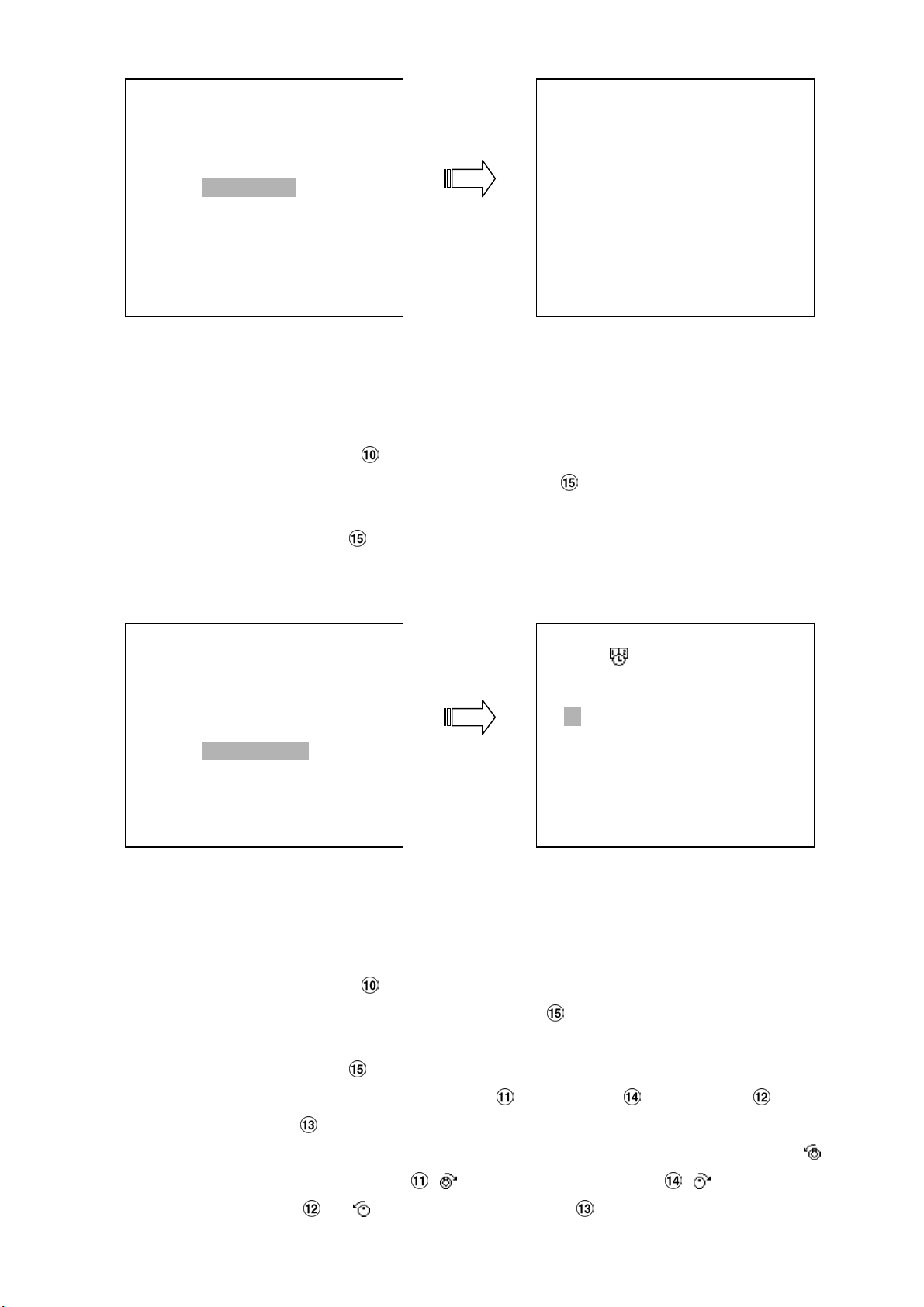
4.4.3 TIME Search
SEARCH
FULL LIST
ALARM LIST
TIME SEARCH
THUMBNAIL
SD CARD
HD 1
A 1 22-18-02 13:22:16 16. 3M
A 2 22-12-03 13:55:45 15. 6M
A 3 22-12-03 14:22:38 17. 8M
A 4 22-12-03 15:22:44 10. 0M
A 5 22-12-03 17:34:12 6. 00M
A 6 22-12-03 18:17:17 4. 00M
A 7 22-12-03 19:12:24 10. 0M
A 8 22-12-03 22:55:50 12. 0M
Take the following steps to proceed with the time-list search function.
(1) Press the Search button to enter the search mode.
(2) Select the
(3) Set the time period you wish to search for the recorded video.
(4) Press the
(5) If no video is found, please return to the time-setting page and repeat steps (3) and (4) again
for another search.
SEARCH
FULL LIST
ALARM LIST
TIME SEARCH
THUMBNAIL
SD CARD
TIME SEARCH and press the Enter button to access the time-setting page.
Enter button to start searching and displaying the concerned image.
DD MM YEAR HH MM
24 / 12 / 2003 00 00
TIME SEARCH
4.4.4 THUMBNAIL Search
Take the following steps to proceed with the thumbnail search function.
(1) Press the Search button to enter the search mode.
(2) Select the
(3) Set the date you wish to search for the recorded video.
(4) Press the
● You can set up by using the “<” button , the “>” button , the “^” button and the
“v” button
● You can also set up by using the Shuttle Ring and the Jog Dial to move eye focus. is
the equal of
“
^” button and is the equal of the “v” button .
THUMBNAIL and press the Enter button to access the thumbnail page.
Enter button to start searching and displaying the concerned image.
to move eye focus.
the “<” button , is the equal of the “>” button , is the equal of the
27
Page 30
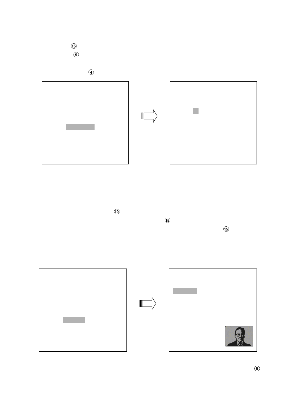
(5) There are 5 levels of recording range modes to choose from:
1 Hour, 10 Minutes, 1 Minute, 10
Seconds
button
button
(6) Once reaching the critical point at any level, the user can start playback by just clicking the
PLAY button .
and 1 Second. Select the specific field of your requirement and press the Enter
to enter the next level. If you want to return the previous level, please press the Setup
SEARCH
FULL LIST
ALARM LIST
TIME SEARCH
THUMBNAIL
SD CARD
THUMBNAIL
DD MM YEAR
22 / 12 / 2003
CHANNEL: 1
4.4.5 SD CARD Search
Take the following steps to proceed with the SD card search function.
(1) Insert a SD Card into the SD card slot of the rear unit.
(2) Press the
(3) Select the
(4) Highlight the specific JPG file of your requirement and press the
image.
(5) If you need another, please return to the SD card JPG file list page and repeat steps (3) and (4)
again for another search.
SEARCH
FULL LIST
ALARM LIST
TIME SEARCH
THUMBNAIL
SD CARD
Search button to enter the search mode.
SD CARD and press the Enter button to access the complete list of JPG files.
Enter button to display the
SD CARD JPG FILE
F0000.JPG
F0001.JPG
F0002.JPG
F0003.JPG
F0004.JPG
F0005.JPG
NOTE: If you would like to delete JPG file in the SD card, please return to SD CARD JPG FILE list
page and highlight the specific JPG file of your requirement and press the
and then select the
“Yes” to delete the image.
28
Setup button
Page 31
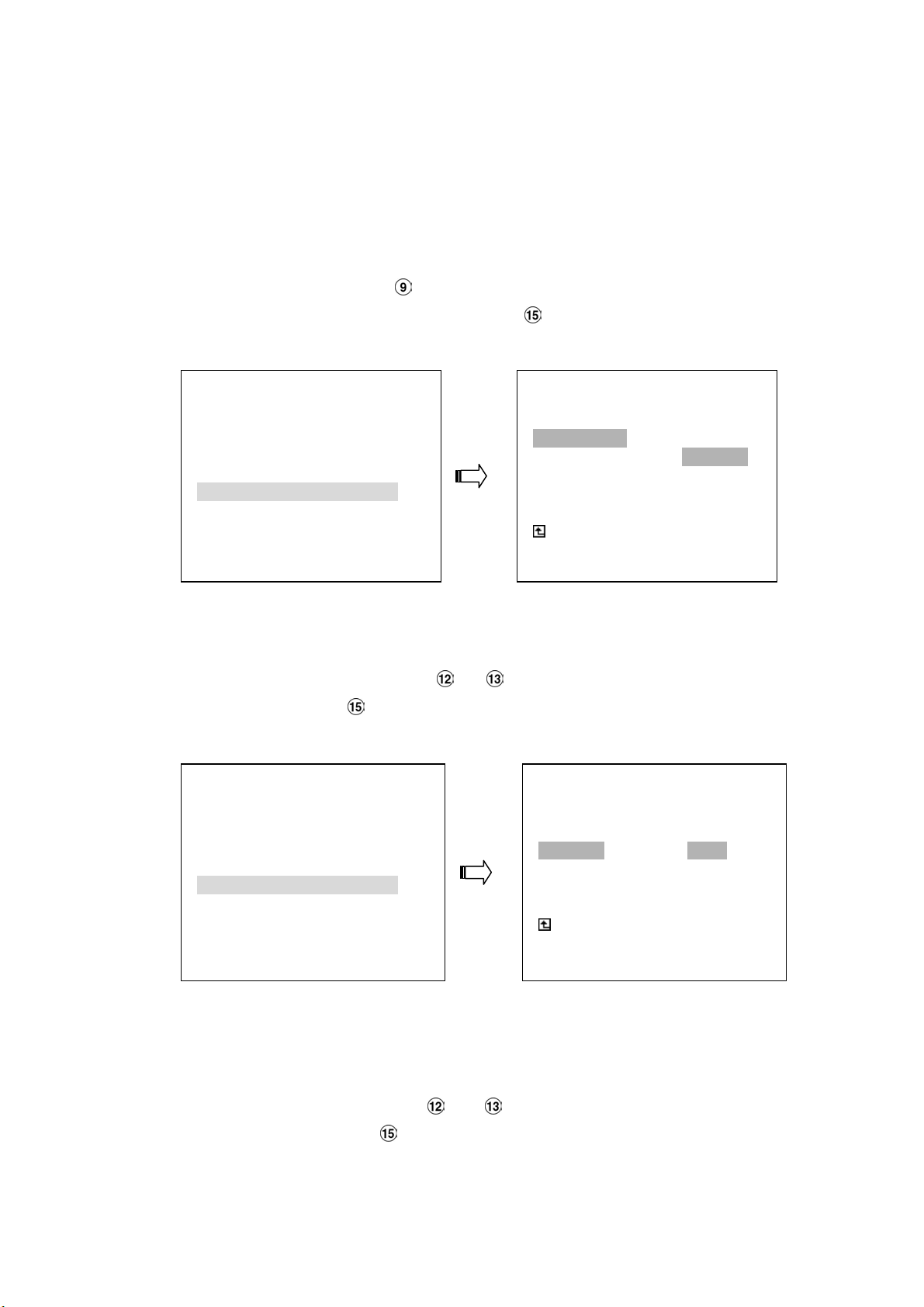
4.5 Backup Operations
4.5.1 Mobile Rack HD Backup Operations
There are three ways available to duplicate the recorded video from HD 1 (Fixed HD) to HD 2
(Mobile Rack HD). Please take the following steps to proceed.
(1) Set HD 2 to BACKUP first. Take the following steps.
Press the Setup button to enter the setup mode and select the DISK.
Highlight DISK and press the Enter button to enter the DISK SETTING page.
Then set HD 2 USAGE to BACKUP.
MAIN MENU
LAN CAMERA
RECORD / BANDWIDTH
CLOCK / TIMER / SEQ
ALARM
COMMUNICATION
DISK
SYSTEM
GOTO DISK PAGE
DISK SETTING
REFORMAT
HD 2 USAGE---------- REC
BACKUP BACKUP
MAIN PAGE
EXT DISK SET TO BACKUP
(2) FULL: Duplicate all the recorded video from HD1 to HD2.
Stay on the DISK SETTING page.
Use the “^” and “v” buttons, and , to highlight BACKUP, select FULL, then press
the
Enter button to proceed.
MAIN MENU
LAN CAMERA
RECORD / BANDWIDTH
CLOCK / TIMER / SEQ
ALARM
COMMUNICATION
DISK
SYSTEM
GOTO DISK PAGE
ALARM: Duplicate all the alarm-event recorded video from HD 1 to HD2.
DISK SETTING
REFORMAT
HD2 USAGE
BACKUP----------------FULL
ALARM
SELECT
MAIN PAGE
BACKUP ALL
Stay on the DISK SETTING page.
Use the “^” and “v” buttons, and , to highlight BACKUP; select ALARM, then
press the
Enter button to proceed.
29
Page 32
MAIN MENU
LAN CAMERA
RECORD / BANDWIDTH
CLOCK / TIMER / SEQ
ALARM
COMMUNICATION
DISK
SYSTEM
GOTO DISK PAGE
REFORMAT
HD2 USAGE
BACKUP----------------FULL
ALARM
SELECT
BACKUP ALARM
DISK SETTING
MAIN PAGE
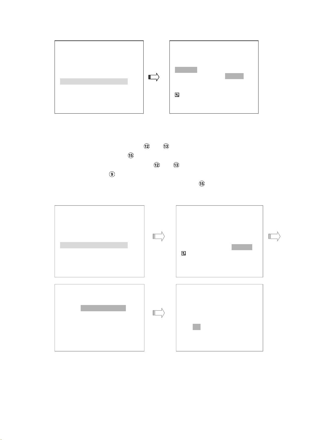
SELECT: Duplicate a particular recorded video from HD1 to HD2.
Stay on the DISK SETTING page.
Use the “^” and “v” buttons, and , to highlight BACKUP, select SELECT and then
press the
Press the “^” and “v” buttons, and , to select the desired clip and press the
Search
After completing the selection, press the Enter button to proceed.
Enter button to list all the recorded video.
button to mark it.
MAIN MENU
LAN CAMERA
RECORD / BANDWIDTH
CLOCK / TIMER / SEQ
ALARM
COMMUNICATION
DISK
SYSTEM
GOTO DISK PAGE
HD1
A 1 2001-02-01 12:20
2 2001-02-01 03:30 +
A 3 2001-03-02 04:20 +
4 2001-04-01 13:30
DISK SETTING
REFORMAT
HD2 USAGE
BACKUP----------------FULL
ALARM
SELECT
MAIN PAGE
BACKUP PART
TOTAL: 41 M
READY TO GO
OK CANCEL
NOTE: If the capacity of HD 2 is not sufficient to store all selected video, a warning message
“HD2 SPACE NOT ENOUGH” will be displayed on the screen. Please, insert a larger
capacity of hard-disk drive and start the process all over again.
30
Page 33

4.5.2 Secure Digital Card (SD Card) Backup Operations
The SD card slot of the rear unit has three functions as shown below:
1. Archive Single image Clips into SD Card
Please take the following steps to archive a critical image in a SD card.
(1) Insert a SD Card into the SD card slot of the rear unit.
(2) Start playing back the recorded video.
(3) Press the
(4) Press the
The quantity of pictures that can be stored depends on the SD card capacity. It depends
on SD card capacity how many pictures can be stored. You can have the saved images
printed out in any computer. The image is stored in the JPEG compressed format. If
more than one clip is stored in a SD card, file names will be assigned in sequence as
shown below.
SAVE TO J0001.JPG
…
SAVE TO J000N.JPG
2. Backup the System setting info into SD Card.
The NVR-2018 offers a quick setup method by using a SD card. If a user wants to set many
NVR-2018 devices with the same settings, the NVR-2018 could save the whole setting in the SD
card, then transfer it to another NVR.
Save the whole setting into the SD card:
Insert a SD card into the SD card slot.
Press the Setup button to enter the setup mode and select the SYSTEM.
Highlight SYSTEM and press the Enter button to enter the SYSTEM SETTING page.
Set SD SETUP to SAVE. Then the system setting info will auto save into SD card.
Transfer the system setting info of NVR to another:
Insert the SD card which has stored the system setting info into the NVR.
Press the Setup button to enter the setup mode and select the SYSTEM.
Highlight SYSTEM and press the Enter button to enter the SYSTEM SETTING page.
Then set SD SETUP to LOAD.
MAIN MENU
LAN CAMERA
RECORD / BANDWIDTH
CLOCK / TIMER / SEQ
ALARM
COMMUNICATION
DISK
SYSTEM
GOTO SYSTEM SETTING
PAUSE button to freeze the desired pictures.
Setup button to save the image in the SD Card.
SAVE TO J0000.JPG
OPERATION LOG : ENTER
OSD LANGUAGE : ENGLISH
MENU BACKGND : 2
BUZZER : ON
PASSWORD : SET
SETUP PWD : OFF
DEFAULT : LOAD
SD SETUP : SAVE
VERSION : ENTER
MAIN PAGE
VIEW OPERATION LOG
SYSTEM
3.
Updating System Software (Please refer to section 3.4 for more details.)
31
Page 34
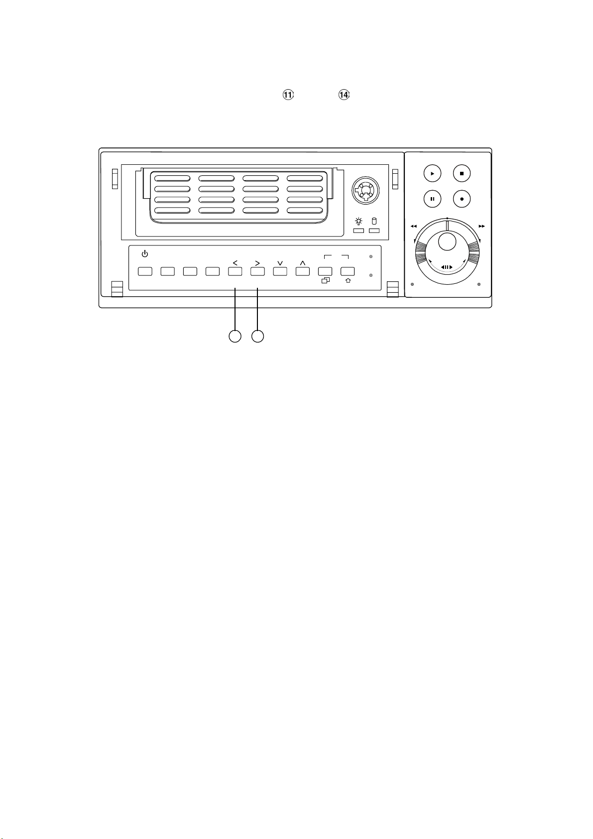
4.6 Key Lock Operation
The Key lock operation protects the unit against unauthorized use by disabling the entire front panel
controls. Simultaneously press these two
3 seconds to lock the unit; to release the
Power Display
Save
Setup
CH1
CH5
11 14
CH2
CH6
“<” and “>” buttons (as shown below) for at least
Key Lock, simultaneously press these two buttons again.
PLAY
STOP
PAUSE
Seq.
Enter
CH4
CH3
CH7
8
4
CH8
Shift
A-recSearch
T-rec
REC
FWDREV
POWERDISK
32
Page 35

5. MENU SETUP
There are 6 categories for operation setting in the setup menu system as shown below. The following
sections will instruct you step by step to configure the operation setting and state each menu’s purpose and
options. Press the
menu allows you to set up the key features of the unit. The functions of various buttons within the menu-setup
mode are described in the paragraphs below.
Setup button to access the setup menu. Once inside the menu system, the on-screen
LAN CAMERA
RECORD / BANDWIDTH
CLOCK / TIMER / SEQ
ALARM
COMMUNICATION
DISK
SYSTEM
MAIN MENU
KEY FUNCTIONS
Setup
Press to enter the setup menu. Press again to exit the setup mode.
“^” “v” buttons and :
Press to select the desired item or entry for setting.
“<” “>”
Press to highlight the desired option or to select the context for setting.
Enter button :
Press to enter the selected item and to save the setting.
button :
buttons and :
Shuttle Ring :
Turn to highlight the desired option or to select the context for setting.
Jog Dial :
Turn to select the desired item or entry for setting.
33
Page 36
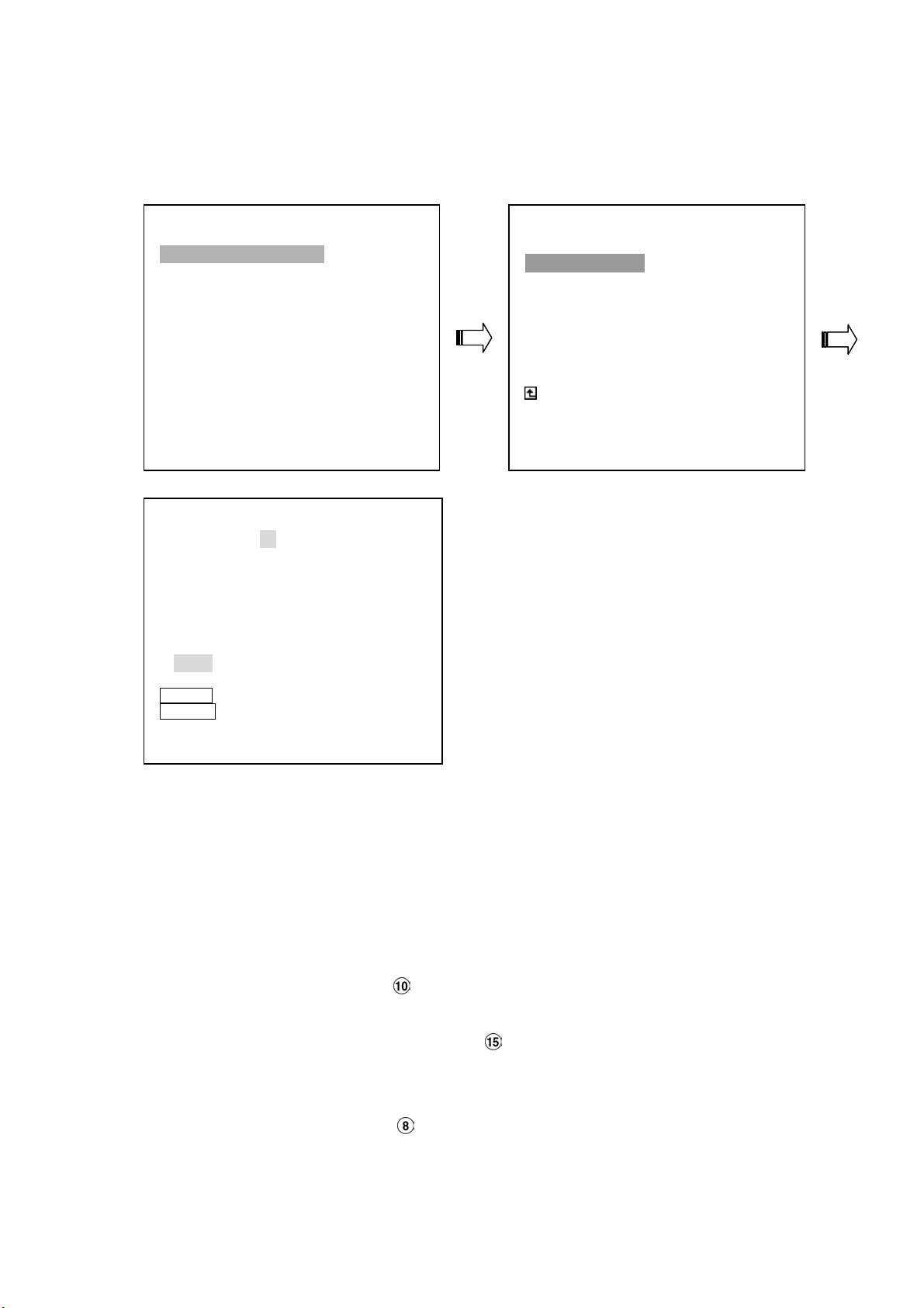
5.1 LAN CAMERA SETTING
This page allows you can select your desired LAN Camera, whose images you can save in the NVR
hard disk. The login name and password must be entered correctly.
LAN CAMERA
RECORD / BANDWIDTH
CLOCK / TIMER / SEQ
ALARM
COMMUNICATION
DISK
SYSTEM
LANCAM SETTING
CHANNEL : 1
CONNECTION : ON
IP : 192.168.001.133
LOGIN NAME [ admin ]
PASSWORD [ 9999 ]
TITLE [ CAM1 ]
OK CANCEL
Search FOR SCANNING
Display FOR TESTING
MAIN MENU
LANCAM SETTING
LANCAM SETTING
IP / ACCOUNT : SET
IMAGE : SET
AUDIO ENABLE : OFF
MOTION : OFF
MAIN PAGE
SET IP AND ACCOUNT
IP / ACCOUNT:
Set the desired channel, entering its number (1 to 8) in the given space. Turn the
“CONNECTION” to “
LAN Camera has its own individual IP. Each IP is a camera, whose “
“
PASSWORD” must be entered correctly.
NOTE: Press the “Search” button to activate “SCANNING” of all the LAN Cameras at
disposal. The screen will display a partial list of cameras, from the desired camera’s IP
can be selected. Push the Enter
that camera.
NOTE: Press the “Display” button
picture appears on a screen at bottom right.
ON”, Provide the corresponding “IP” address in the “IP” entry, because each
LOGIN NAME” and
button to automatically display the chosen IP of
to trigger the “TESTING” function. Immediately a
34
Page 37
MAIN MENU
LAN CAMERA
RECORD / BANDWIDTH
CLOCK / TIMER / SEQ
ALARM
COMMUNICATION
DISK
SYSTEM
LANCAM SETTING
IMAGE SETTING
RESOLUTION : 352 X 240
QUALITY : HIGHEST
LANCAM PAGE
SET IMAGE RESOLUTION
LANCAM SETTING
IP / ACCOUNT : SET
IMAGE : SET
AUDIO ENABLE : OFF
MOTION : OFF
MAIN PAGE
IMAGE SETTING
IMAGE SETTING
RESOLUTION : 352 X 240
720 X 480
SET
LANCAM PAGE
SET IMAGE RESOLUTION INDIVIDUALLY
RESOLUTION SETTING
CH1 CH2 CH3 CH4
352 X 240 352 X 240 352 X 240 352 X 240
CH5 CH6 CH7 CH8
352 X 240 352 X 240 352 X 240 352 X 240
OK CANCEL
IMAGE SETTING
QUALITY : HIGHEST
HIGH
MEDIUM
LOW
LOWEST
SET
LANCAM PAGE
SET QUALITY TO HIGHEST FOR EACH CH
QUALITY SETTING
CH1 CH2 CH3 CH4
HIGHEST HIGHEST HIGHEST HIGHEST
CH5 CH6 CH7 CH8
HIGHEST HIGHEST HIGHEST HIGHEST
OK CANCEL
35
Page 38

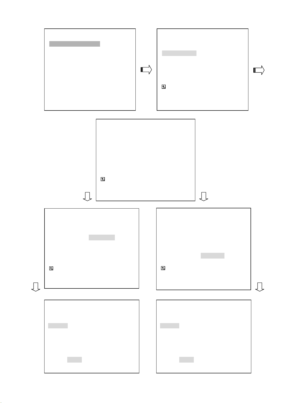
IMAGE:
(1) Press the
(2) Select the item termed "
LANCAM SETTING page.
(3) Select the item termed "
SETTING
(4) To regulate the image resolution function, set the "
"
720 x 480". In either case, all channels will convert to your desired mode. If, however, you
wish to set individual channels in different modes, please select "
set individual channels in different modes and then push the
legends "
and the “
your choice(s). If not, press "
(5) To regulate image quality, you can use the “
of the five levels of quality provided here, ranging from the "
you select any of these levels, all your channels will convert to that level. If, however, you
wish to set individual channels in different levels of quality, please got to “
function. After set individual channels in different modes and then push the
Setup button to enter the MAIN MENU.
LAN CAMERA" and press the Enter button to enter the
IMAGE" and push the Enter button to enter the IMAGE
page.
RESOLUTION" either to "352 x 240", or to
SET" for this function. After
Enter button . At once the
OK" and "CANCEL" appear at the bottom of the page. Now press the “<” button
>” button to confirm either "OK" or "CANCEL" respectively. Press "OK" to ratify
CANCEL".
^” button and the “v” button to select any
HIGHEST" to the "LOWEST". If
SET” for this
Enter button .
At once the legends "
“
<” button and the “>” button to confirm either "OK" or "CANCEL" respectively. Press
"
OK" to ratify your choice(s). If not, press "CANCEL".
OK" and "CANCEL" appear at the bottom of the page. Now press the
36
Page 39

MAIN MENU
LAN CAMERA
RECORD / BANDWIDTH
CLOCK / TIMER / SEQ
ALARM
COMMUNICATION
DISK
SYSTEM
LANCAM SETTING
LANCAM SETTING
IP / ACCOUNT : SET
IMAGE : SET
AUDIO ENABLE : OFF
MOTION : OFF
MAIN PAGE
SET AUDIO ENABLE
LANCAM SETTING
AUDIO ENABLE : OFF
MAIN PAGE
SET AUDIO ON/OFF INDIVIDUALLY
ON
SET
AUDIO ENABLE:
(1) Press the Setup button to enter the MAIN MENU.
(2) Select the item termed "
LAN CAMERA" and press the Enter button to enter the
LANCAM SETTING page.
(3) Select the item termed "
AUDIO ENABLE" and push the Enter button to select the
AUDIO ENABLE SETTING
CH1 CH2 CH3 CH4
OFF OFF OFF OFF
CH5 CH6 CH7 CH8
OFF OFF OFF OFF
OK CANCEL
AUDIO ENABLE.
(4) To activate the motion detection function, set "
function, set "
channels in the
AUDIO ENABLE" to " OFF" The items termed "OFF" and "ON" switch all the
AUDIO ENABLE SETTING page off and on respectively as well. If you wish
to select individual channels for sounds, select the item termed "
desired channels by pressing them "
ON" while turning the rest "OFF". After set individual
channels in different modes and then push the
and "
CANCEL" appear at the bottom of the page. Now press the “<” button and the “>”
button
choice(s). If not, press "
to confirm either "OK" or "CANCEL" respectively. Press "OK" to ratify your
CANCEL".
AUDIO ENABLE" to "ON". To deactivate the
SET" and activates your
Enter button . At once the legends "OK"
37
Page 40
LAN CAMERA
RECORD / BANDWIDTH
CLOCK / TIMER / SEQ
ALARM
COMMUNICATION
DISK
SYSTEM
LANCAM SETTING
MAIN MENU
LANCAM SETTING
IP/ACCOUNT : SET
IMAGE : SET
AUDIO ENABLE : OFF
MOTION : SET
MAIN PAGE
MOTION SETTING
MOTION SETTING
MOTION ENABLE : ON
SENSITIVITY/REGION : CH1
LANCAM PAGE
SET MOTION ENABLE
MOTION ENABLE : ON
SENSITIVITY/REGION : CH1
LANCAM PAGE
SET MOTION SENSITIVITY/REGION
MOTION SETTING
MOTION ENABLE : OFF
LANCAM PAGE
SET MOTION ENABLE
MOTION SETTING
ON
SET
MOTION ENABLE
SENSITIVITY/REGION : CH1
LANCAM PAGE
SET MOTION OF CH5
MOTION SETTING
CH2
CH3
CH4
CH5
CH6
CH7
CH8
MOTION ENABLE SETTING
CH1 CH2 CH3 CH4
ON ON ON ON
CH5 CH6 CH7 CH8
ON ON ON ON
SENSITIVITY / REGION SETTING
SENSITIVITY HIGHEST
REGION ( 30, 25 ) – ( 90, 70 )
OK CANCEL
38
OK CANCEL
Page 41

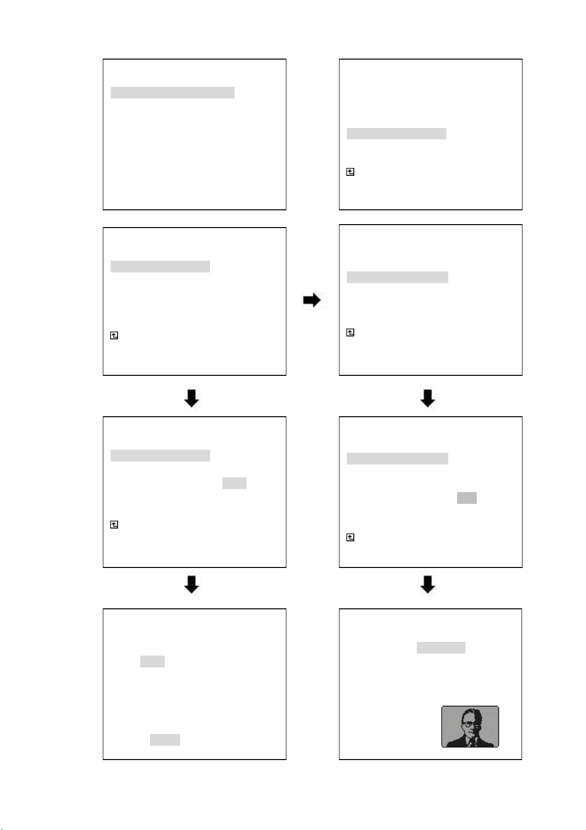
MOTION:
Take the steps detailed below to activate a programmed motion detection. For MOTION SETTING,
as well as its two distinct functions of
MOTION ENABLE and SENSITIVITY / REGION.
(1) Press the
(2) Select the item termed "
LANCAM SETTING page.
(3) Select the item termed "
SETTING
(4) To activate the motion detection function, set "
function, set "
channels in the
to select individual channels for viewing, select the item termed "
desired channels by pressing them "
by pressing "
(5) In the
the “>” button
Setup button to enter the MAIN MENU.
LAN CAMERA" and press the Enter button to enter the
MOTION" and push the Enter button to enter the MOTION
page.
MOTION ENABLE" to "ON". To deactivate the
MOTION ENABLE" to " OFF" The items termed "OFF" and "ON" switch all the
MOTION ENABLE SETTING page off and on respectively as well. If you wish
ON" while turning the rest "OFF". Confirm your choices
OK". If not, push "CANCEL".
MOTION SETTING page, select the entry termed "SENSITIVITY / REGION" and press
to show all the channels in their order, each in turn. Use the “^” button
SET" and activates your
and the “v” button
set the channel in the
other channels you choose.
(6) To set "
choose your degree of sensitivity and then push the
"
OK" and "CANCEL" appear at the bottom of the page. Now press the “<” button and the
“>” button
SENSITIVITY" and "REGION" for activation on the SENSITIVITY / REGION page,
to confirm either "OK" or "CANCEL" respectively.
to select a desired channel for setting. Press the Enter button and
SENSITIVITY / REGION SETTING page. Repeat the process for all
Enter button . At once the legends
5.2 REC SETTING
This page allows you to set the recording rate and recording quality, and enables you to continue
recording when the disk is full.
MAIN MENU
LAN CAMERA
RECORD / BANDWIDTH
CLOCK / TIMER / SEQ
ALARM
COMMUNICATION
DISK
SYSTEM
GOTO REC PAGE
MAX REC RATE : UNLIMIT
BANDWIDTH : UNLIMIT
DISK FULL : REWRITE
SET MAX REC RATE
REC / PLAY SETTING
MAIN PAGE
39
Page 42

MAX REC RATE:
This option is used for limiting the number of pictures recorded every second into a storage disk.
The recording rate controls the maximum of the frequency at which the number of video pictures
can be recorded.
● There are 4 different recording rates you can select from: UNLIMIT, 30F/S, 20F/S, and
10F/S.
NOTE: The maximum of pictures is averagely shared among all channels.
BANDWIDTH:
This option determines the bandwidth to be recorded. There are seven levels of bandwidth you
can select from:
50K, 100K, 200K, 300K, 400K, 500K,and UNLIMIT. Selecting the UNLIMIT for
use provides bandwidth unlimited for each channel recorded images, and normally records
more images than a 50K, 100K, 200K, 300K, 400K and 500K. To regulate bandwidth, you can
use the “
provided here, ranging from the "
^” button and the “v” button to select any of the seven levels of bandwidth
UNLIMIT" to the "50K". If you select any of these levels, all
your channels will convert to that level. If, however, you wish to set individual channels in
different levels of bandwidth, please got to “
in different modes and then push the
"
CANCEL" appear at the bottom of the page. Now press the “<” button and the “>” button
SET” for this function. After set individual channels
Enter button . At once the legends "OK" and
to confirm either "OK" or "CANCEL" respectively. Press "OK" to ratify your choice(s). If not,
press "
DISK FULL:
CANCEL".
This option determines the way to utilize storage media in case of a full disk.
REWRITE: When the hard-disk is full, the device continues recording by displacing the old data.
STOP: When the hard-disk is full, the device will stop recording.
40
Page 43
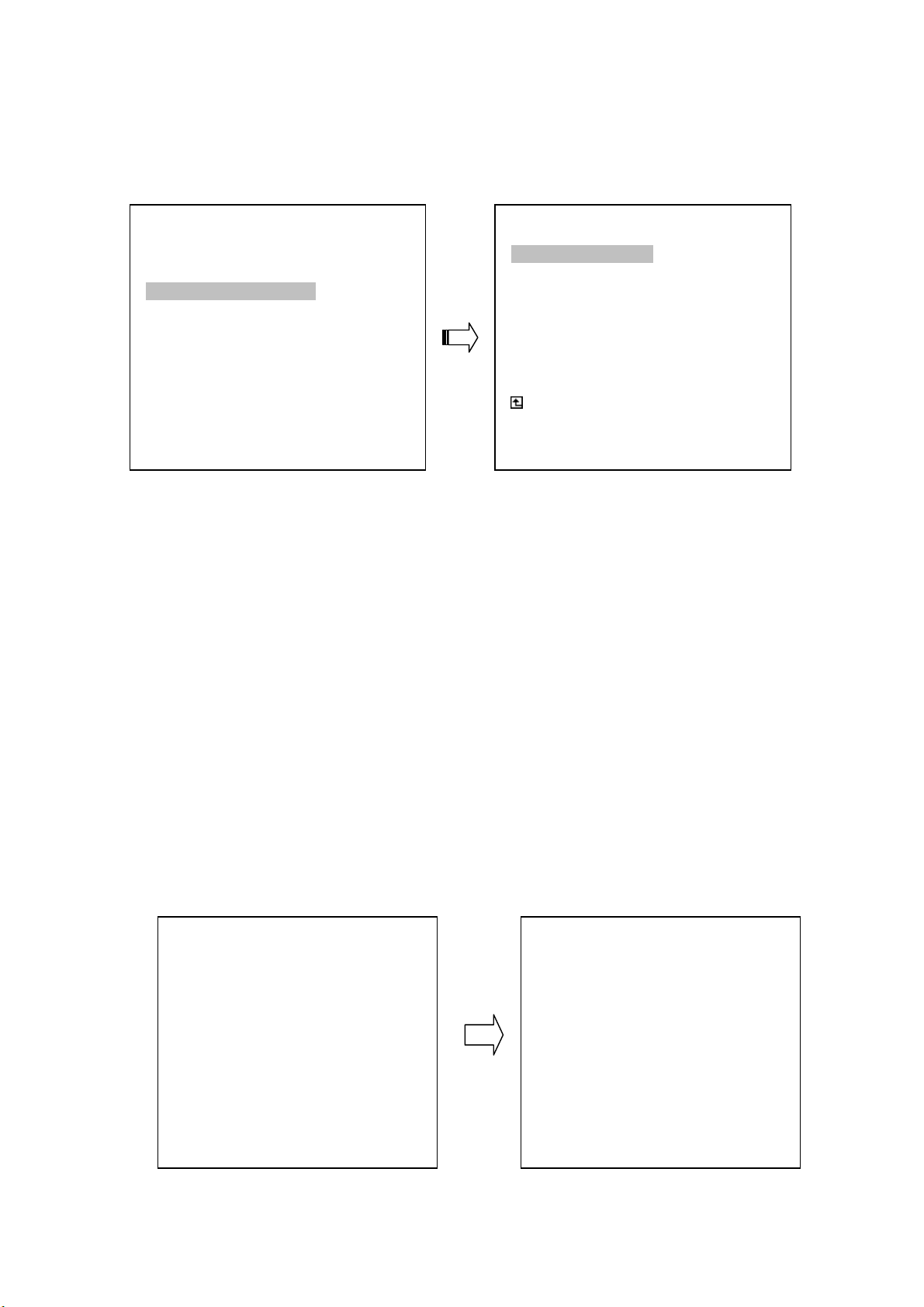
5.3 CLOCK / TIMER / SEQ SETTING
The NVR provides a weekly table, consisting of two periods of time each day for scheduled recording.
This option allows you to set the time each day that the NVR will start and stop recording.
MAIN MENU
LAN CAMERA
RECORD / BANDWIDTH
CLOCK / TIMER / SEQ
ALARM
COMMUNICATION
DISK
SYSTEM
CLOCK SETTING : SET
TIMER : SET
SEQUENCER : SET
GOTO CLOCK / TIMER / SEQ PAGE
CLOCK SETTING:
This entry allows users to set the system time.
NOTE: Clock data is retained for about 3 months after the 15-hour power supply is used up
(Operate On mode).
SET CURRENT CLOCK
CLOCK / TIMER / SEQ
MAIN PAGE
TIMER:
This entry allows users to program the time each day that the NVR will start and stop recording. There
are two time periods each day available for scheduling. The time is displayed in a 24-hour clock format.
If there is a time overlapping showing between two continual time period settings, the device will
automatically combine the two time-period settings into one combined time-period setting.
TIMER ENABLE: This option enables/disables the programmed scheduled recording.
ON: Enables the scheduled recording.
OFF: Disables the scheduled recording.
REC SCHEDULE
TIMER ENABLE: ON
START END START END
S 06:00-16:00 12:00-18:00
●
●
●
●
TIMER ENABLE: ON
START END START END
S 06:00-18:00 00:00-00:00
REC SCHEDULE
●
●
●
●
41
Page 44
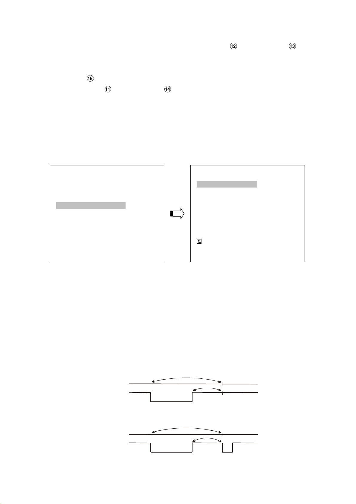
SEQUENCER:
A
g
A
g
To regulate dwell time of the sequencer, you can use the “
dwell time provided here, ranging from the "
00" to the "30".you can set individual channels in different
^” button and the “v” button to select
dwell time. After set individual channels, quad and multi screen in different modes and then push the
Enter button . At once the legends "OK" and "CANCEL" appear at the bottom of the page. Now
press the “
"
OK" to ratify your choice(s). If not, press "CANCEL".
<” button and the “>” button to confirm either "OK" or "CANCEL" respectively. Press
5.4 ALARM SETTING
This menu allows users to program the configuration of alarm recording only when an alarm input is
activated. The device will record as long as the alarm input is activated.
MAIN MENU
LAN CAMERA
RECORD / BANDWIDTH
CLOCK / TIMER / SEQ
ALARM
COMMUNICATION
DISK
SYSTEM
GOTO ALARM PAGE
ALM OPERATION : OFF
ALM DURATION : 30 SEC
MAX REC RATE : UNLIMIT
PRE- ALARM : ON
MAIN PAGE
ALARM REC ENABLE
ALARM SETTING
ALM OPERATION:
This option determines whether to activate/deactivate the alarm recording when it detects an alarm input.
ON: The device activates the alarm recording when it detects an alarm signal from LANCAM.
OFF: The device ignores the alarm signal when it detects an alarm signal from LANCAM.
ALM DURATION:
This option allows users to set alarms for a certain duration. You can select one of the six following
options:
0 SEC, 30SEC, 1 MIN, 5 MIN, 10 MIN, and NON-STOP.
Duration
Setting
Non-Stop
Alarm
activated
larm recordin
Alarm
deactivated
larm recordin
Duration
Duration
Alarm
activated
Alarm
deactivated
Reset
42
Page 45

MAX REC RATE:
This option is the number of pictures recorded every second into a storage disk when an alarm input is
activated. There are 2 different record speeds you can select
REMAIN for use, the device will record images at the same speed as set on the REC page.
PRE- ALARM:
This option determines that images prior to an alarm occurs will be recorded in the hard-disk drive.
When an alarm is triggered the device will record the image prior to the alarm for up to 256 images.
ON: Enables this function.
OFF: Disables this function.
NOTE: If the device is already under recording mode before alarm occur, the pre-alarm
recording would not take effect.
UNLIMIT or REMAIN. If you select
43
Page 46
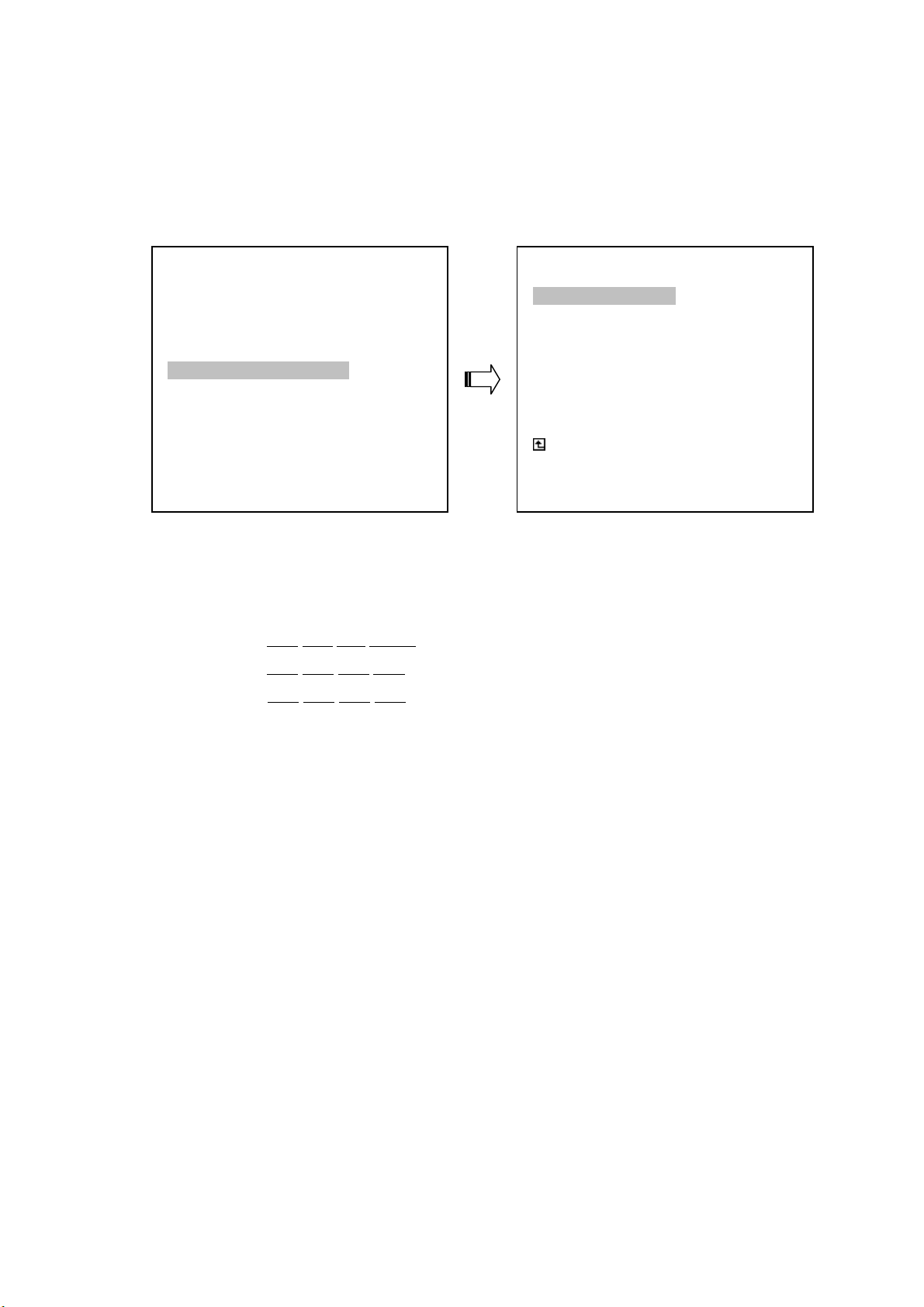
5.5 COMMUNICATION
This option allows you to configure the status of the RS-232 communication port when connected to an
external device, and the Ethernet communications settings. (Please refer to the RS-232 Protocol and
Network Function for more details)
MAIN MENU
LAN CAMERA
RECORD / BANDWIDTH
CLOCK / TIMER / SEQ
ALARM
COMMUNICATION
DISK
SYSTEM
GOTO COMM PAGE
NET IP : SET
NET DHCP : SERVER
LEASED IP TABLE : ENTER
IP POOL RANGE : SET
COMM ID : 01
RS232 : ON
MAIN PAGE
SET NETWORK
COMM SETTING
NET IP:
This option is used to configure the Ethernet communication settings. This is required for the purpose of
making a network connection. Please consult with a qualified MIS professional to configure it.
IP: XXX.YYY.ZZZ.WWW
MASK: XXX.XXX.XXX.XXX
GATEWAY:
XXX.XXX.XXX.XXX
NET DHCP:
This option selects CLIENT, SERVER or OFF for the DHCP communication function.
OFF: Disables it.
CLIENT: Disables it.
SERVER: Enables it.
NOTE: The range of available IP to be leased by DHCP server is from XXX.YYY.ZZZ.1 to
XXX.YYY.ZZZ.254 except for NVR’s IP XXX.YYY.ZZZ.WWW.
NOTE:
LEASED IP TABLE:
Show DHCP leased IP table.
If provided with a DHCP server, the NVR-2018 can get an IP automatically by setting this
option to CLIENT.
44
Page 47
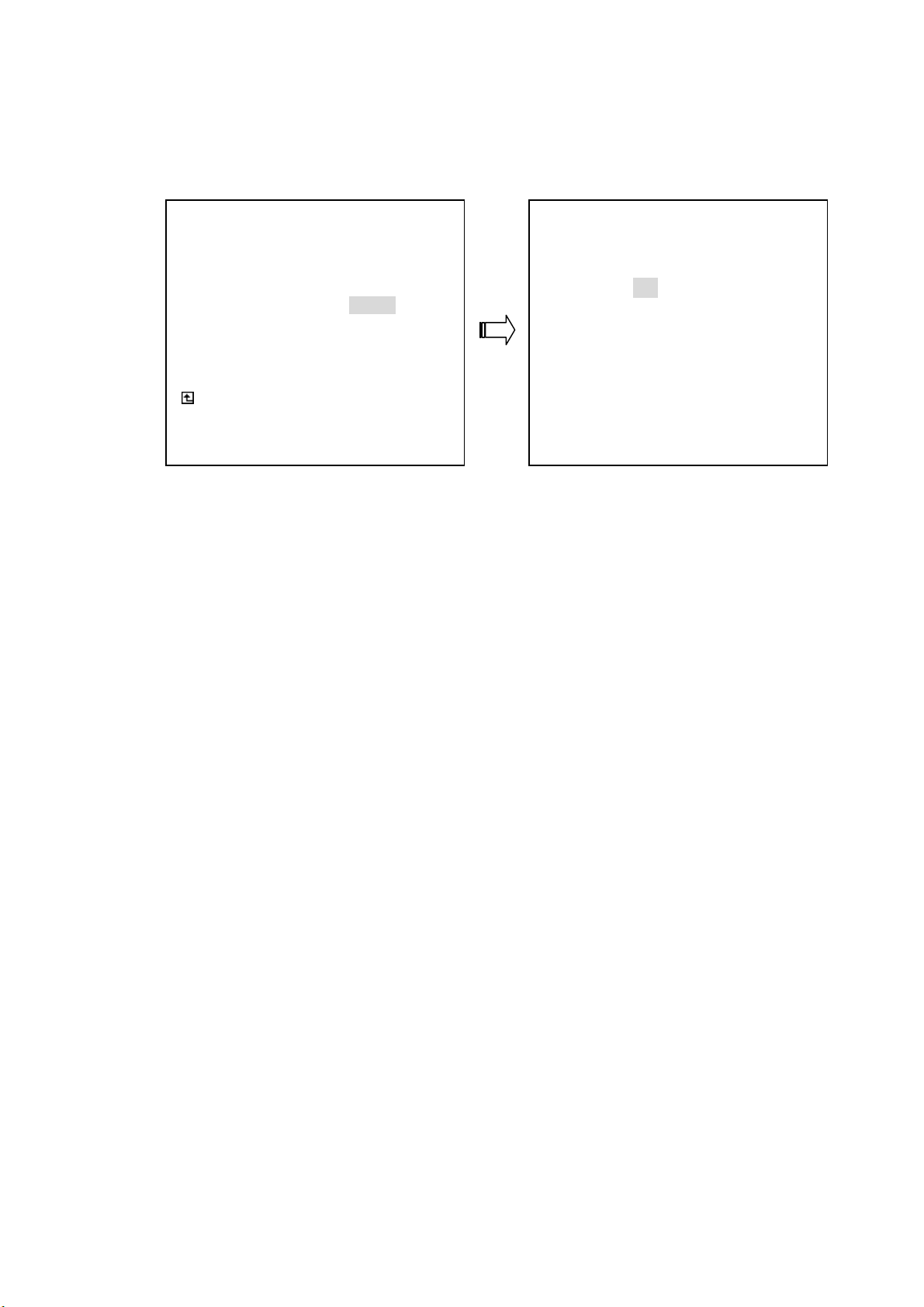
IP POOL RANGE:
You can set your DHCP IP address by changing only the last part of the four - part IP address given
below. The last part can be any number selected from a range between 1 and 254.
NET IP
NET DHCP
LEASED IP TABLE
IP POOL RANGE SET
COMM ID
RS232
MAIN PAGE
SET IP POOL RANGE
COMM ID:
Communication ID for RS232 communication. After the NVR-2018 receives a RS232 command,
it checks if the <Dest ID> within the code is the same as the COMM ID, in which case the
particular command can be accept.
RS-232:
COMM SETTING
IP POOL RANGE SETTING
192.168. 1. 1 ― 192.168. 1.254
SET IP POOL RANGE
The RS-232 communication port can be either in an importing or exporting mode according to your
applications.
ON: Enables the RS-232 communication port. When you wish the unit to be controlled
by an external device, please select this entry for use.
OFF: Disables the RS-232 communication port.
45
Page 48
5.6 DISK SETTING
MAIN MENU
LAN CAMERA
RECORD / BANDWIDTH
CLOCK / TIMER / SEQ
ALARM
COMMUNICATION
DISK
SYSTEM
GOTO DISK PAGE
REFORMAT:
This option allows you to clear out all the data in the hard-disk drive. You will be required to enter the
pre-set password before proceeding with clearing out the data. Enter the standard password “9999” if
you don’t set your individual password. To set your individual password, please refer to section 5.7
PASSWORD option.
REFORMAT : HD 1
HD 2 USAGE : REC
HD BACKUP : FULL
MAIN PAGE
DISK REFORMAT/CLEAR
DISK SETTING
HD 1 : Clears out all the data stored in HD 1 and HD 2.
BACKUP HD: Clears out all the data stored in HD 2, which is set to backup purpose only.
(This function has to be proceeded with when the
BACKUP.)
HD2 USAGE:
This option determines the way to utilize the hard-disk drive in the mobile compartment.
BACKUP: Used for data backup only, which will not be part of regular recording hard-disk
drive.
REC: Used for the regular recording hard-disk drive.
NOTE: When you wish to play back a recorded video from a HD2, this option must be set to
REC. For more details, please refer to section 4.3.4.
HD BACKUP:
This function allows you to duplicate data from HD 1 to HD 2. Please set HD 2 as BACKUP first. (For
operation details, please refer to section 4.5.1)
HD 2 USAGE option is set to
FULL: Duplicates all the recorded video from HD1 to HD2.
ALARM: Duplicates all the alarm-event recorded video from HD 1 to HD2
SELECT: Duplicates a particular recorded video from HD1 to HD2.
46
Page 49
5.7 SYSTEM SETTING
This page is used for accessing the history of the operation status, setting the password, resuming
factory default, and determining the menu display background.
MAIN MENU
LAN CAMERA
RECORD / BANDWIDTH
CLOCK / TIMER / SEQ
ALARM
COMMUNICATION
DISK
SYSTEM
GOTO SYSTEM SETTING
OPERATION LOG:
This log shows the history of the operation status in chronological order. What the following entries
represent is detailed below.
ON: Powers up the device.
OFF: Powers off the device.
REC: Starts recording.
STOP: Ceases recording.
PLAY: Shows recorded video.
P-LOSS: Power interruption occurs.
A-IN: Detects an alarm input.
LOCK:
Disables the entire front panel controls.
OPERATION LOG : ENTER
OSD LANGUAGE : ENGLISH
MENU BACKGND : ON
BUZZER : ON
PASSWORD : SET
SETUP PWD : OFF
DEFAULT : LOAD
SD SETUP : SAVE
VERSION : ENTER
MAIN PAGE
VIEW OPERATION LOG
05/15/03 18:19:32 ON
05/15/03 18:19:32 OFF
05/15/03 18:19:32 REC
05/15/03 18:19:32 STOP
05/15/03 18:19:32 PLAY
05/15/03 18:19:32 M-IN 1
05/15/03 18:19:32 C-BRK 1
05/15/03 18:19:32 P-LOSS
SYSTEM
UNLOCK:
UPDATE:
M-IN 1:
M-OUT 1:
C-BRK 1:
Note: The log keeps an operation history on a revolving basis because of a limit is 4000. When
the log is full, the newly registered record of an operation will replace the existing records
Releases the key lock.
Updates system software.
Detects a motion input in channel 1.
Detects a motion stop in channel 1.
Connecter interruption occurs in channel 1.
47
Page 50

from the oldest one.
OSD LANGUAGE:
This option allows you to select the OSD language display as English, or Chinese.
MENU BACKGND:
There are 3 levels of background color transparency, you can choose from : level 1 is totally
transparent, level 3 is opaque, and level 2 is between level 1 and 3. The background color is
used in setup menu and search function.
BUZZER:
This option determines the embedded buzzer sounding a tone to signal the following situations.
A tone lasts about two seconds long.
ON: Enables buzzer.
OFF:
Disables buzzer.
Situation
Alarm occurs
Video loss occurs
Disk is full
Load factory default
Buzzer set to ON
Enable/disable key lock function
Power on /off mobile rack HDD
Backup operation complete
Timer activate/deactivate
Recording switching between HDD
PASSWORD:
This option allows you to set a password to prevent any unauthorized re-formatting of the hard
disk drives or use by a network viewer. The standard password is “9999”.
OLD PASSWORD: Enter the pre-set password (or the standard password if this is the
initial setting) to access the password setting system.
NEW PASSWORD: Enter a 4-digit-number password of your choosing which will replace
the pre-set password (or the standard password “9999”).
SETUP PWD:
When this option is on, user must pass the password check before entering the setup menu.
ON: Enables it.
OFF: Disables it.
48
Page 51

DEFAULT:
This option allows you to reload the factory default setting. Please do note that the
password can not be changed in the factory default setting.
SD SETUP:
The NVR-2018 offers a quick setup method by using a SD card. If the user wants to set up many a
number of the same devices with the same settings, he can save the whole settings to a SD card,
then transfer to another NVR.
SAVE: Saves the whole setting to the SD card.
LOAD: Loads the whole setting to the SD card.
VERSION:
This item is in the setup menu reveal network MAC, BIOS version, and software version, and last
updated date.
MAC : 00 : 0c : 0c : 00 : 00 : 07
BIOS : 1.03
S/W : 0.35
DATE : Dec 24 2003
49
Page 52
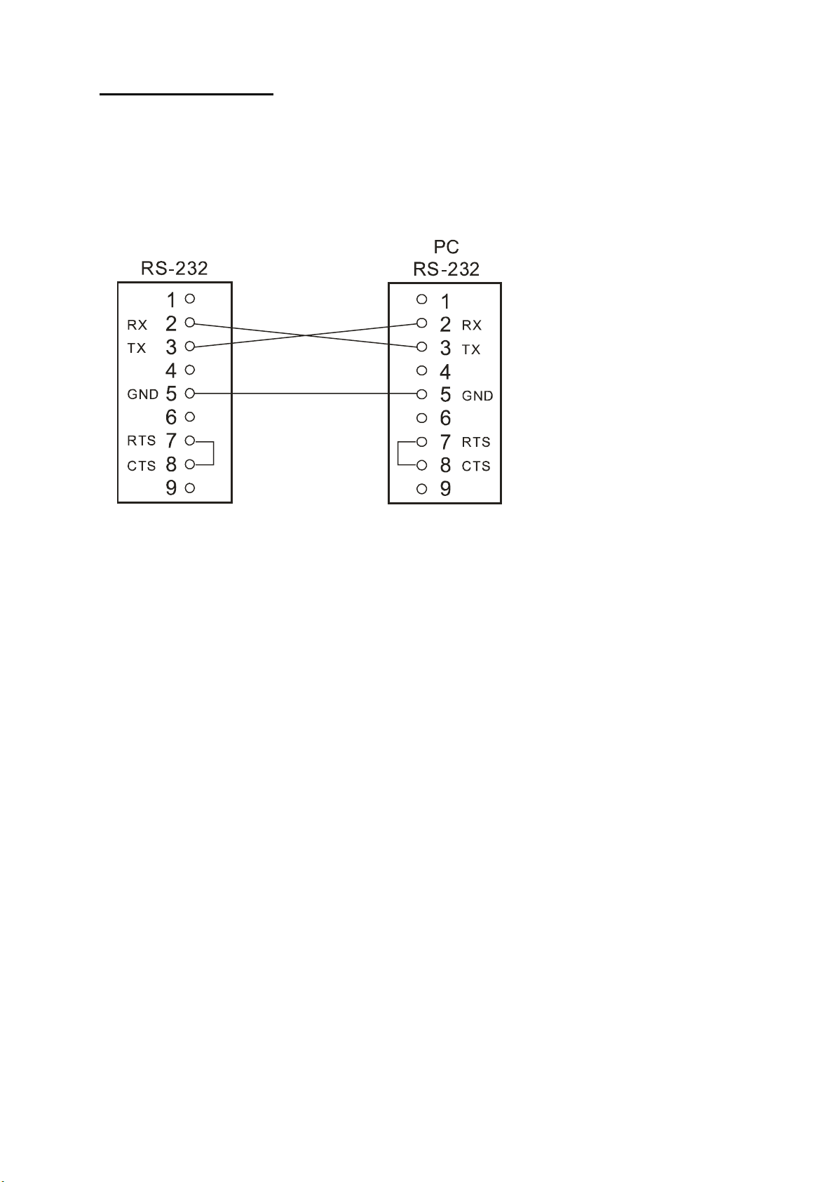
6. RS-232 Protocol
6.1 Setup
6.1.1
Use a Null Modem cable (the standard RS-232 9 Pin Cable with Pin 2 and Pin 3 exchanged, see
pin configuration chart below for details) to connect the COM 1 on the rear panel of the NVR to a
PC.
NVR
6.1.2 Set the RS-232 option to ON in the COMMUNICATION page of the setup menu.
6.1.3 Set the PC communication parameters: 9600 bps, No Parity, 8 Data Bits, 1 Stop Bit.
6.2 Communication Protocol
6.2.0 General Command Format
<Lead Code = 0x41>, < Dest ID >, < Src ID >, <Main category >, <Second category >, {<Number of
parameters>,<Parameter 1>, <Parameter 2> ..,} <End Code= 0x4f>
Lead Code = 0x41
Dest ID = 0x01
Src ID = 0x20
Main Category = 0x01
Second Category = 0x01 Handshake
= 0x02 Request Time/Set Time
= 0x06 Request System State
End Code= 0x4f
6.2.1 Keys and signals
= 0x02 Command
The different command types and their corresponding parameters are as follows:
PC Send: <0x41>, <0x01>, <0x20>, <0x01>, <Key Value(Low byte)>,
<Key Value(High byte)>,<0x4f>
Keys and Signals
= 0x0b Time Search
50
Page 53

< The value of a specific front panel key >
KEY_PLAY 1
KEY_STOP 3
KEY_PAUSE 4
KEY_POWER 5
KEY_REC 6
KEY_SETUP 7
KEY_ENTER 8
KEY_SEARCH 10
KEY_DISPLAY 11
KEY_UP 13
KEY_DOWN 14
KEY_LEFT 15
KEY_RIGHT 16
KEY_SHIFT 36
JOG_L 128
JOG_R 129
KEY_SHIFT_LEFT 140
KEY_SHIFT_RIGHT 141
KEY_SHIFT_DOWN 142
KEY_SHIFT_UP 143
KEY_SHIFT_ENTER 144
KEY_SHIFT_DISPLAY 145
KEY_SHIFT_SEARCH 146
KEY_SHIFT_SETUP 147
KEY_SHIFT_POWER 148
KEY_SHIFT_PLAY 149
KEY_SHIFT_PAUSE 150
KEY_SHIFT_REC 151
KEY_SHIFT_STOP 152
KEY_SHUT_L8 160
KEY_SHUT_L7 161
KEY_SHUT_L6 162
KEY_SHUT_L5 163
KEY_SHUT_L4 164
KEY_SHUT_L3 165
KEY_SHUT_L2 166
KEY_SHUT_L1 167
KEY_SHUT_CT 168
KEY_SHUT_R1 169
KEY_SHUT_R2 160
KEY_SHUT_R3 161
KEY_SHUT_R4 162
KEY_SHUT_R5 163
KEY_SHUT_R6 164
KEY_SHUT_R7 165
SIGNAL_POWER 256
SIGNAL_REC_IN 257
SIGNAL_REC_OUT 258
6.2.2 COMMAND Types
6.2.2.1 Handshake (Second Category=0x01)
6.2.2.0 Command (Main Category=0x02)
PC Request: <0x41>, <0x01>, <0x20>, <0x02>, <0x01>, <0x00>, <0x4f>
NVR Response: <0x41>, <0x20>, <0x01>, <0x02>, <0x08>, <0x00>, <0x4f>
51
Page 54

PC Request: <0x41>, <0x01>, <0x20>, <0x02>, <0x02>, <0x07>, < 7 Time Value >, <0x4f>
2001/06/20 17:05:00 = <0xD1>, <0x07>, <0x06>, <0x14>, <0x11>, <0x05>, <0x00>
NVR Act: Changing the time and date.
6.2.2.2 Request Time (Second Category=0x02)
PC Request: <0x41>, <0x01>, <0x20>, <0x02>, <0x02>, <0x00>, <0x4f>
NVR Response: <0x41>, <0x20>, <0x01>, <0x02>, <0x02>, <0x07>, <7 Time Value >, <0x4f>
The following case is an illustration of
2001/06/20 17:05:00 = <0xD1>, <0x07>, <0x06>, <0x14>, <0x11>, <0x05>, <0x00>
6.2.2.3 Set Time (Second Category=0x02)
The following case is an illustration of < 7 Time Value>
6.2.2.4 Request State (Second Category=0x06)
PC Request: <0x41>, <0x01>, <0x20>, <0x02>, <0x06>, <0x00>, <0x4f>
NVR Response: <0x41>, <0x20>, <0x01>, <0x02>, <0x06>, <0x01>,
<System State = 0..>, <0x4f>
Description of <System State>:
STATE_INIT 0
STATE_LIVE 1
< 7 Time Value>
STATE_REC 2
STATE_PLAY 3
S_STATE_PAUSE 4
STATE_NET_PLAY 5
STATE_NET_PAUSE 6
STATE_RESTART 7
STATE_SETUP 8,9
STATE_MENU 10,11,12,13,14,15
STATE_DHCP_WAIT 16
STATE_SEARCH 17
STATE_BACKUP 18,19
6.2.2.5 Time Search (Second Category=0x0b)
PC send: <0x41>, <0x01>, <0x20> ,<0x02>, <0x0b>, <0x06>, <6 Bytes Date/Time>, <0x4f>
where < 6 bytes Date/Time >, = year(2 bytes, =LowByte + HighByte*256), month ( 1 byte),
day (1 byte), hour(1 byte),min(1 byte)
Example: to search 06/12/2002 17:00 the Date/Time =
<0xd2>,<0x07><0x06>,<0x0b>,<0x11>,<0x00> where 2003= 210(=0xd3) + 7(=0x07) *256
NOTE: The NVR accepts RS-232 time search commands only under the live or playback Mode.
52
Page 55
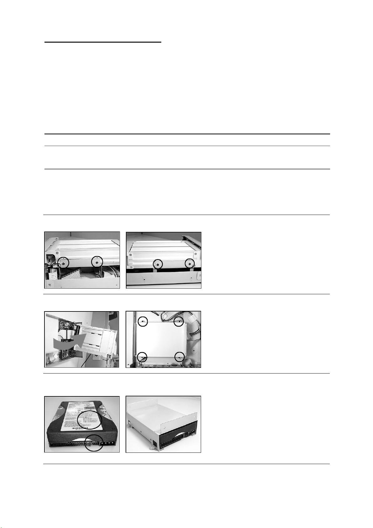
7. IDE Hard Disk Installation
Usually, the unit comes with one hard-disk drive installed in compartment HD 1, which is default-configured as a
master. The jumper settings configuration of the installed hard-disk drives for the unit and compatible drives
which can be used with this unit are listed in the table below. To install two hard disk drives in compartment HD 1
and HD 2, please take the following steps.
The jumper settings of hard-disk drives for the system
IDE 1 Compartment HD 1 Master
IDE 2 Compartment HD 2 Master
7.1 Built-in hard disk
1.
2.
Location Jumper
1. Unscrew all the mounting screws on the
mobile rack of the unit and detach it.
3.
2. Carefully lift the mobile rack to a vertical
4.
position.
3. Unscrew the secured screws to detach
the hard disk rack.
4. Setting the jumper of your hard disk
5.
driver. The way to set the jumper of the
drive varies between manufacturers;
please refer to the instructions on the
driver to set the jumpers in the master
position.
5. Place the hard disk in the rack.
53
Page 56
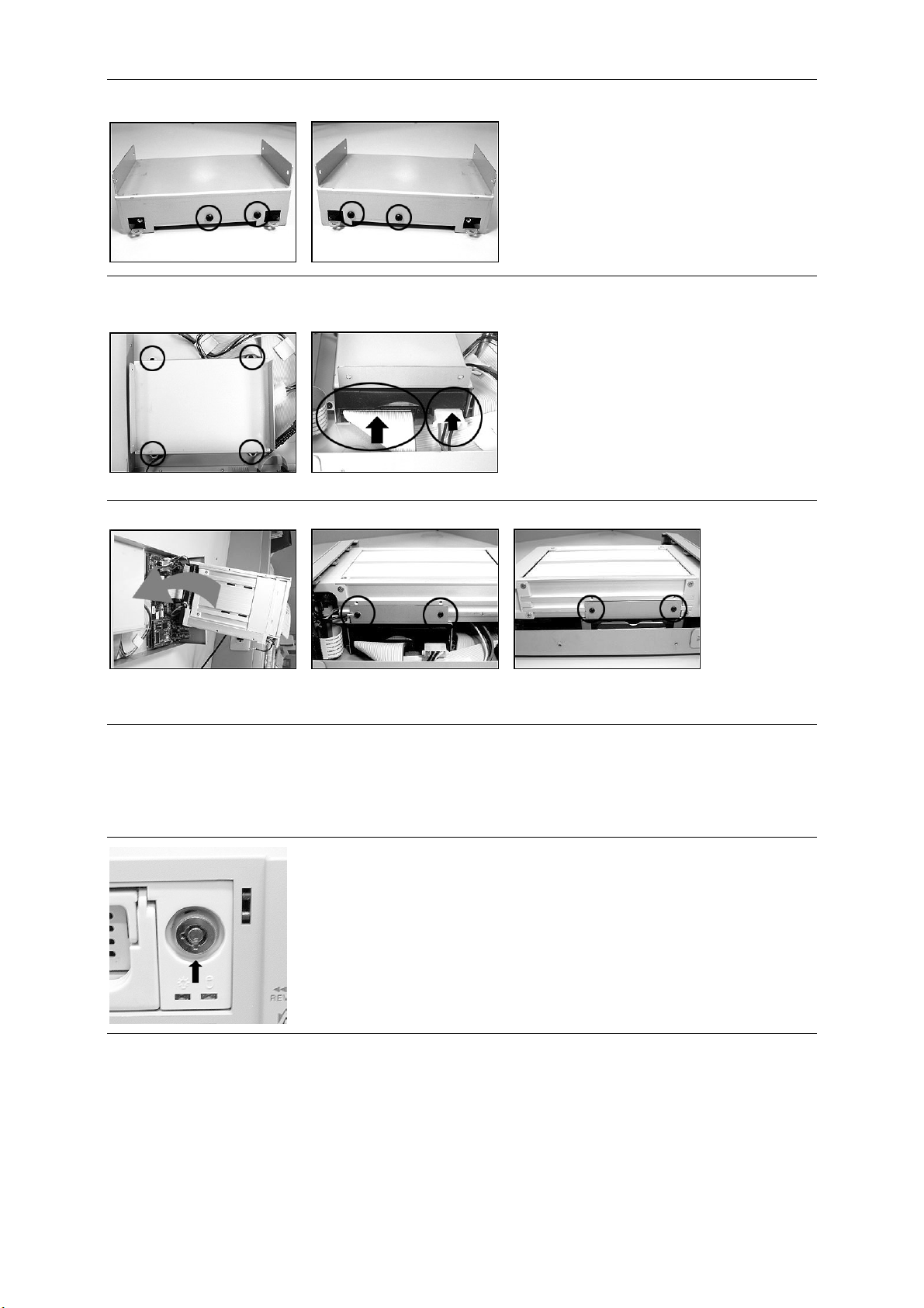
6.
A
6. Secure the driver in the rack using two
mounting screws in both the
side-mounting holes. Please don’t
tighten the screws too much, otherwise
that may damage the driver.
7.
8.
10.
Place the mobile rack back onto the device and screw it in.
7. Screw the rack into the device, screwing
in all the four screws.
8.
ttach the interface connector and the
power connector to the drive. Please
note the red lining of the IDE cable and
the red wire of power cable must line up
side by side.
7.2 Mobile Rack
1. Make sure that the key unlocked.
54
Page 57
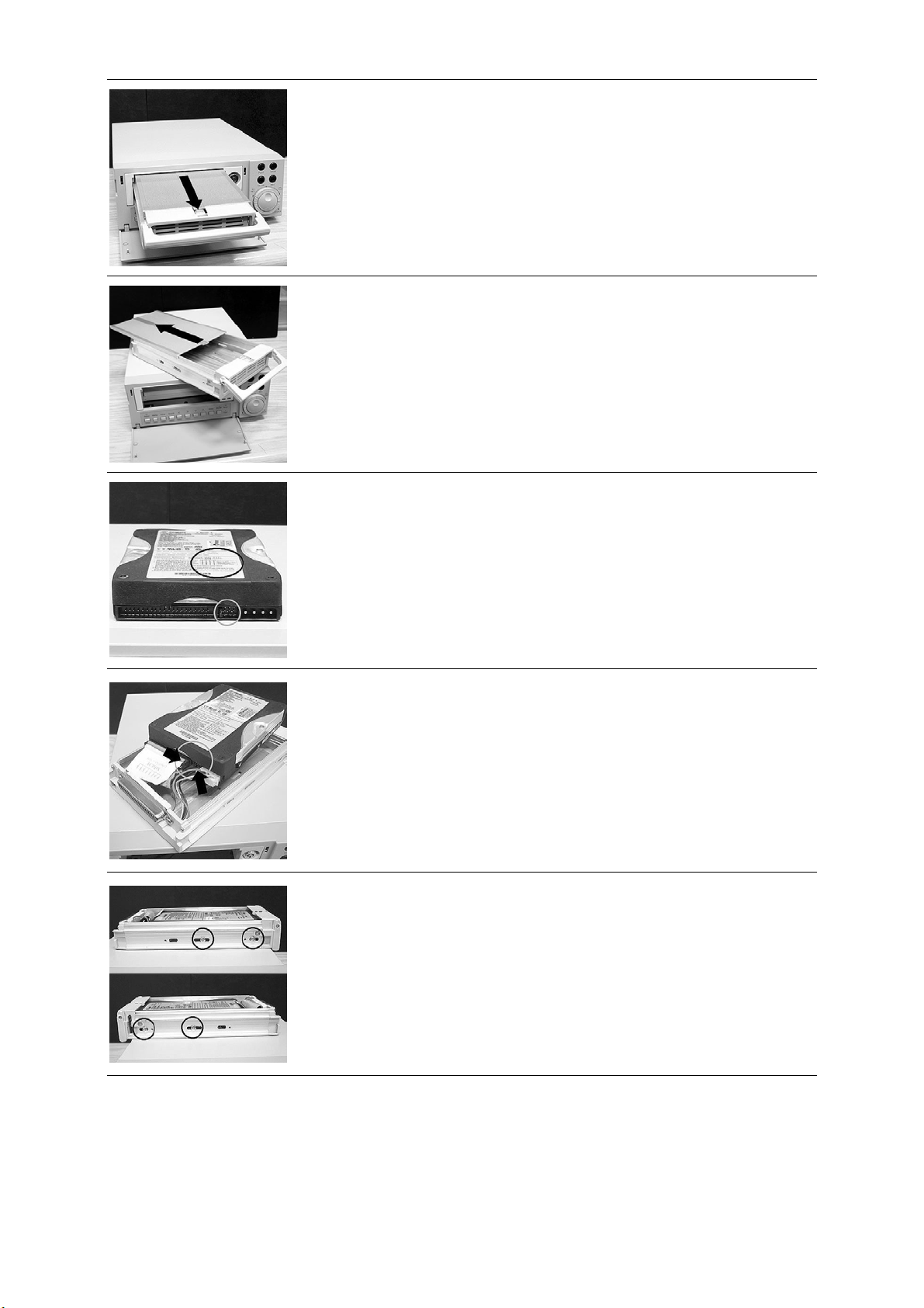
2. Pull the active-handle outward to remove the carrier body away from
the mobile rack
3. Slide the top cover backward and remove.
4. Setting the jumper of your hard disk driver. The way to set the jumper
of the drive varies between manufacturers; please refer to the
instructions on the driver to set the jumpers in the master position.
5. Attach the interface connector and the power connector to the drive.
Please note the red lining of the IDE cable and the red wire of power
cable must line up side by side.
6. Place the HDD inside mobile rack, Use four of the provided screws.
55
Page 58
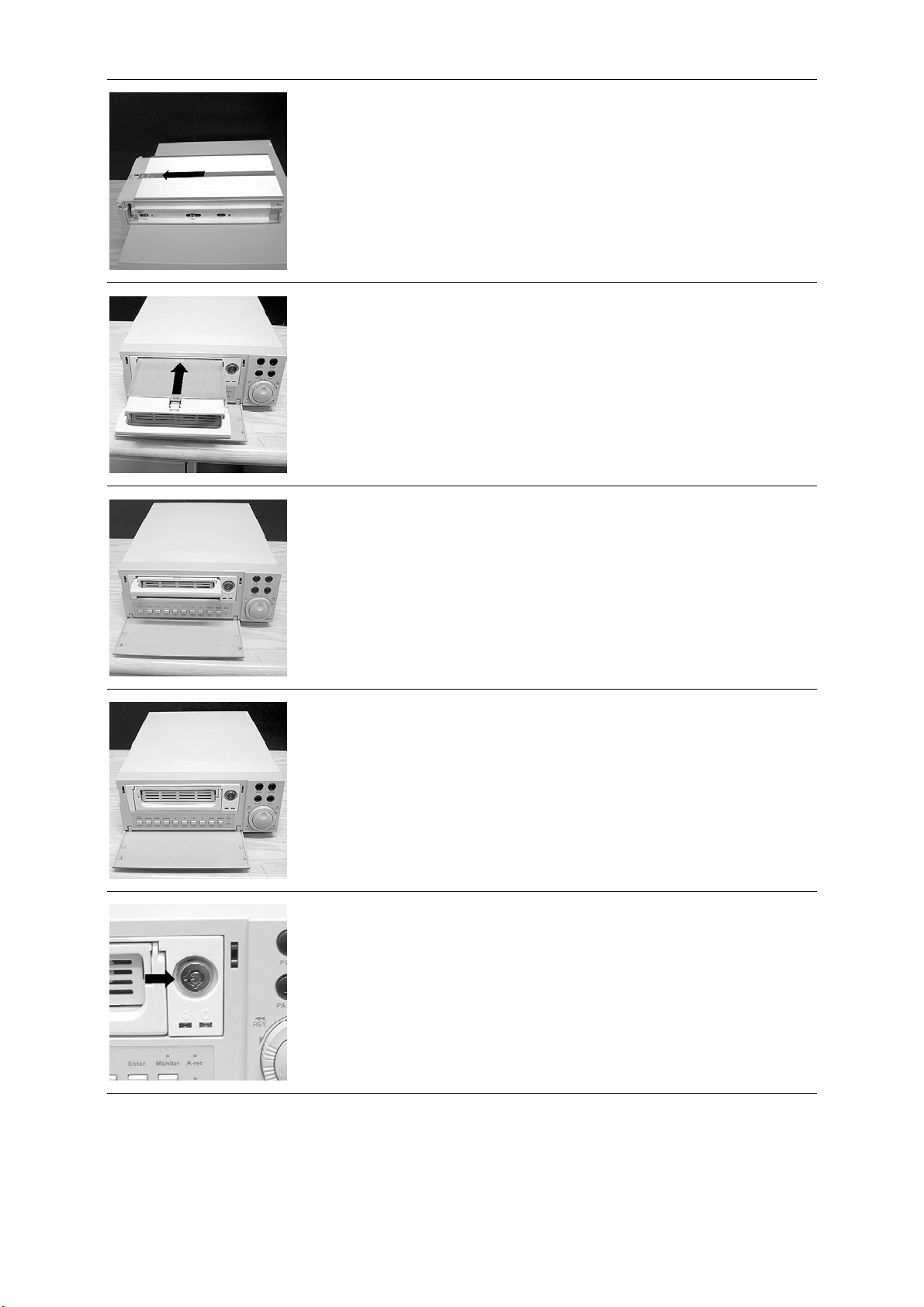
7. Place the top cover back to the carrier body by sliding forward to
secure.
8. Slide the carrier body back in the mobile rack.
9. Push the carrier body further into the mobile rack until fully inserted.
10. Push the active-handle inward.
11. Lock the Key.
56
Page 59

8. O.S.D Message
No. O.S.D Message Meanings
1 NO DISK No hard-disk detected after power activated
2 BATTERY LOW Suggest change the battery and reset the system time
3 LOADING System Boot up
4 KEY LOCKED Key lock function is on
5 KEY UNLOCKED Key lock function is off
6 n1 OF n2 ITEMS PROGRESS n3 % BACKUP n1/n2 NOW
7 BACKUP COMPLETE Backup complete
8 HD2 SPACE NOT ENOUGH HD2 has not enough space for backup
9 NO ENTRY FOR BACKUP No backup is possible.
10 BACKUP INCOMPLETE
11 NOT FOUND The system cannot find a video in the Search function.
12 END Playback of recorded video has reached the end point
13 DISK FULL
14 EMPTY
15 SET TO NTSC, PLS RESTART
16 SOFTWARE UPDATE Software update
17 PLEASE RESTART
18 NO DISK
19 DATA NOT CONTINUOUS
20 DISK ATTACHED HD2 has been attached.
21 DISK REMOVED HD2 has been removed.
Backup incomplete, since the user has pressed the STOP
button to stop it
Hard-disks are full; this happens only when the DISK FULL
item in the setup menu is set to STOP.
The user presses the PLAY button or uses the SEARCH
function, but no video can be played.
System has to be set to NTSC, please reboot (PAL is
similar)
The system should be rebooted after the software has
been updated
The user has pressed the Save key without putting in a SD
card, or there is a disk error.
The system finds data in installed HDs cannot be used
contiguously. Suggest you remove HD2 from the system.
22 FAN STOPPED The chassis fan has stopped for over 30 seconds.
23 HDn ERROR AT xxxxx
24 NOT PRESENT
25 SAVE TO DISK Start saving to the JPEG file.
26 SAVE TO Fnnn. JPG Save to Fnnn. JPG (where nnn= 0..999)
27 SAVE OK Save to the JEPG is ok.
28 SD CARD WRITE PROTECT A SD card is write-protected; or there is an error
There is a hard-disk error during recording, where n is the
hard-disk number and xxxxx is the hexadecimal location.
When the user tries to clear a disk that was not attached in
the setup menu.
57
Page 60

9. Network Viewer and Image Viewer
t
This section provides instructions for installing and using the Network Viewer, and Image Viewer, which are
included with the NVR. The programs can be operated by a selected PC equipped with the following
requirements.
1. Intel Pentium 233MHz at least.
2. 32 MB RAM
3. Window 95, 98, NT, and ME.
4. 4 MB Video card capable of 24-bit true color display.
5. 5 MB free hard-disk space for software installation.
6. 10-base T network for LAN operation.
9.1 The Network Viewer
9.1.1 Introduction to Network Viewer
The Network Viewer allows you to potentially access unit of the NVR from a remote desktop or a laptop in a
TCP/IP networking environment. It can perform the following functions.
View live images from the NVR
Store, search, and review recorded video from the NVR HDD.
Change the regular record, event record, and timer properties.
Before you are ready to view images from a desktop, you need to have your NVR networked by obtaining a
10 base Ethernet data cable (Standard RJ-45) to connect the NVR to your LAN/WAN. Now enter the main
menu to set the IP address.
NVR-2018
RJ-45
PC
RJ-45 PIN configuration for Ethernet
PIN NO. PIN Assignment
1. TX +
2. TX -
3. RX +
4. Not Connected
5. Not Connected
6. RX -
7. Not Connected
8. Not Connected
RJ-45 socke
1 2 3 4 5 6 7 8
58
Page 61

Physical specification for Ethernet
Wire Type
Connector Type
Max. Cable Length
Hub Wiring Configuration
PC Wiring Configuration
NOTE: For more details on network connections, please refer to the following document.
Cat. 5
RJ-45
30 m
Straight Through
Cross Over
9.1.2 Install the Network Viewer in your PC
Install the Network Viewer from the supported CD-R.
1. Exit all applications currently running in the selected PC.
2. Insert the supported CD in the CD-ROM drive. The program will execute the installation automatically.
Follow the on-screen instructions to proceed with the rest of the installation procedure as they appear.
3. After the installation is complete, pop up the
/ APPRO NVR Network Viewer
to open up the program selection page as shown below. Click the
START menu from your computer, and point to Programs
APPRO NVR Network Viewer tag to start the APPRO NVR Network Viewer program.
Install the Network Viewer for the ZIP file.
1. Save the ZIP file to your PC and extract the file to a designated directory.
2. Open the extracted folder.
3. Click on the
icon to execute the installation and then follow the on-screen instructions to
proceed with the rest of the installation procedure as they appear.
4. After the installation is complete, pop up the
/ APPRO NVR Network Viewer
NOTE: Please make sure the TCP/IP communication software has been properly set and configured
in your computer. To check your TCP/IP settings, refer to the following document.
to start the APPRO NVR Network Viewer program.
START menu from your computer, and point to Programs
59
Page 62
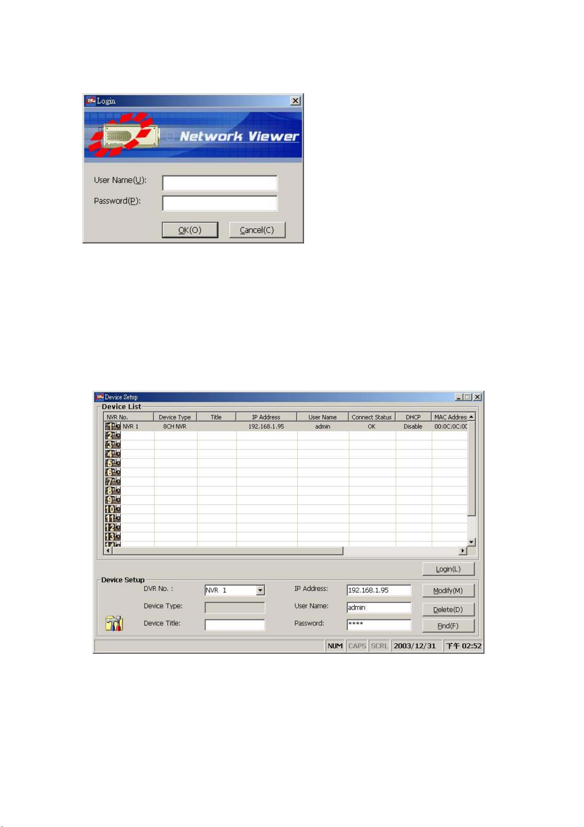
9.1.3 View the NVR video from a remote PC
Once Network View is executed a Login prompt will
appear, you must enter the default User Name:
admin, password: 9999 into the respective field and
click on OK to log into the application.
Follow the instructions below to use the Network
Viewer to browse a NVR video from a remote
location. Upon entering the Network Viewer, the
connection box will appear as follows.
1. Click the
2. Choose a channel number from the Channel drop-down list.
3. Type in the user name for the chosen NVR.
4. Type in the password of the device and click the
5. Please repeat steps 2 to 4
6. Select the NVR to enter this device.
7. Click the
Find tag to connection of the all NVR device in the LAN.
again for another desire.
Login tag to begin viewing images.
Modify tag to add the device to the Device List.
NOTE: Upon connection, the connection status box indicates the name and IP address of the
selected device. If there’s a failure to connect, a “Fail” message appears on the screen
right after the device IP address; otherwise an “OK” appears. To add more connections or
units to the NVR, please repeat the above instructions.
60
Page 63
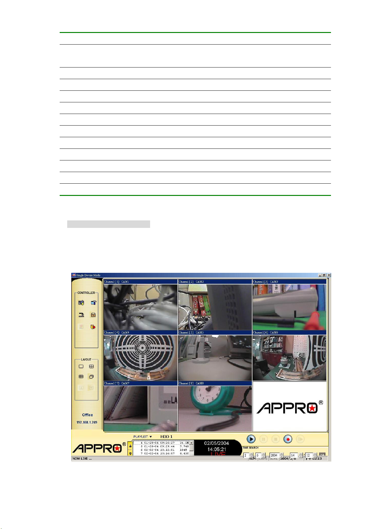
Functions Description
Device List
NVR Number
Device Type
Device Title
IP Address
User Name
Password
Add
Modify
Delete
Find
Login
Viewing images
View the connected device
Displays the entire list of connected devices if and as necessary. This list
includes a lot of information about all the connected devices.
Assigns a display location when you have multiple devices connected.
Displays the device type.
This blank allows you to assign a label to the chosen device.
Type in the IP address which you preset for the device
This space allows you to assign a name to the chosen device.
Type in the preset password for making a connection.
Click to add the settings of a chosen device.
Click to change the settings of a chosen device.
Click to remove the connection of a chosen device.
Click to find the connection of the all NVR device in the LAN.
Click to access the display page of the Network Viewer.
Once the connection has been established, click the Login tag to enter the single-device mode window.
(See the sample screen below) This window displays the connected device in the sequence which has
been arranged when you established the connection.
61
Page 64
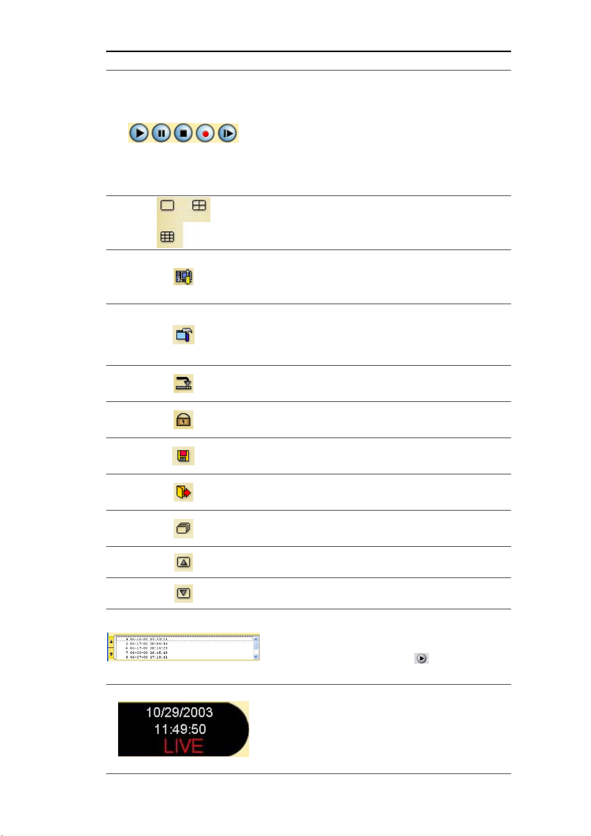
Function Buttons Description
Playback function bar.
Play- Click to a recorded video from the PLAY
LIST.
Pause- Click to freeze the image.
Stop- Click to stop playing back the recorded video
or cease recording.
REC- Click to activate the recording function of the
device.
Step- Click to view images picture-by-picture.
The Split-Screen display function bar. This allows you to
display the connected device in the multi-format screens
of 1, 2x2 and 8.
Press to enter the PC SYSTEM SETUP window, which
allows you to program the System Setup, Record Setup,
and Alarm Setup.
Press to enter the LANCAM setting window, to open the
device setting page to add more devices for viewing,
Which allows you to program the Record Setting and
Record Schedule.
Click to minimize the Network Viewer into a PC system
tray.
Click to lock the system.
Click to save a viewing image in the local computer.
Press to leave the Network Viewer program.
The single sequence.
Click to page up.
Click to page down.
Recorded video list box. This box allows you to access
all recorded video, which are stored in the HDD of the
connected devices. To review a recorded video, just click
an entry from the list and click the
PgUp/PgDn: To scroll up and down the list.
button.
NVR Status Box. This box indicates the selected device
status.
PLAY: The device is in the playback mode.
LIVE: The device is in the live display mode.
WAIT: The device is processing the command.
PAU SE: Pauses the image.
62
Page 65
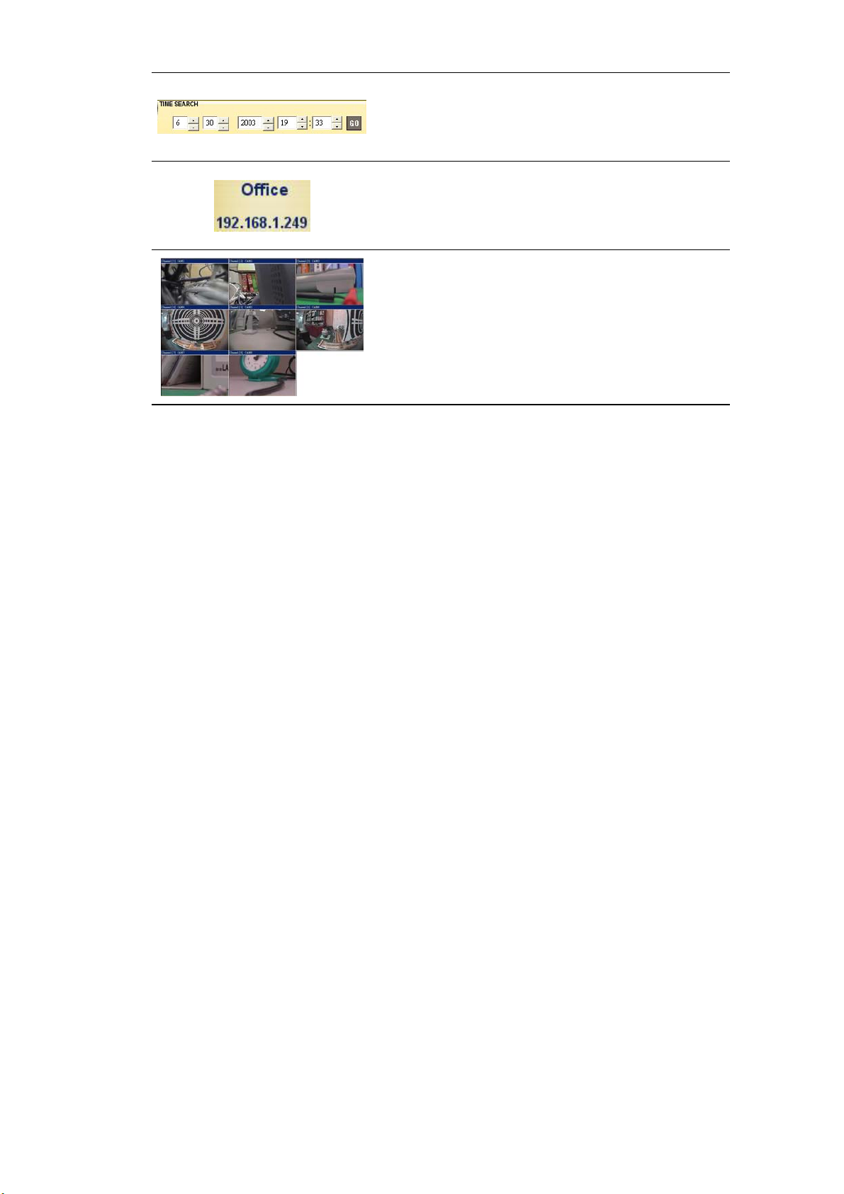
This allows you to search a recorded video kept in the
HDD of the device. Enter the MONTH/DAY/YEAR
HOUR: MINUTE you wish to search and click GO to
proceed.
Every NVR has to own an IP address and a title to be
identified on the network. This area displays the title and
the IP address of the NVR.
Image display area. Displays the images of each camera
and the title information on the top blue bar. Double click
the image to view a full screen of the camera.
63
Page 66
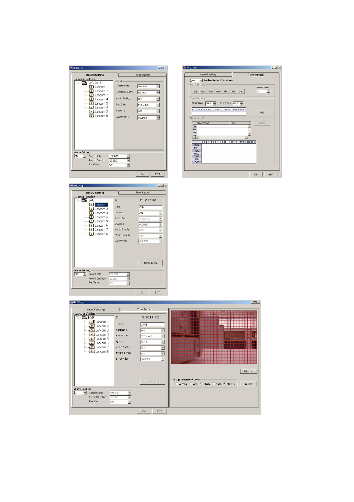
9.1.4 Change the Record & Timer Properties Via the Network
Follow the instructions below to reconfigure the record and schedule recording settings via the network.
A. B.
C
D
64
Page 67

Set the regular record settings
1. When in the single –device mode, click to enter the SETUP page. (See the sample screen as in A
above)
2. Select a desired recording rate and Quality from the corresponding drop-down list
3. At the left of the page are itemized Lancam 1(
screen as in C above), each of which is connected to the corresponding camera. So, if you click any
of them, the corresponding camera’s information will appear in the blank spaces of all the items on
the screen.
4. Adjust the LANCAM setup, including all the items on the screen given below:
Title
Connect LanCam
Motion (See the sample screen as in D above)
The information in all the above items’ attached spaces can be sent to the NVR.
5. Click the
Set the Alarm record settings
1. When in the single –device mode, click
above)
2. Set the ALRM SETTING to ON to enable the drop-down list in the ALARM SETTING area.
3. Select a desired recording rate and Quality from the corresponding drop-down list.
4. Click the OK tag to proceed.
OK tag to proceed.
to enter the SETUP page. (See the sample screen as in A
) to 8( ) (See the sample
Set the Record Schedule
1. When in the single –device mode, click
B above)
2. Set the
3. Click the
&
4. When all required settings are completed, click
Record Schedule to ON to enable the Record Schedule setting area.
Time-Period button to set the schedule for recording for each day. Go to both the START TIME
END TIME boxes, enter a specific Hour: Minute and click Add button to add to the Record List.
to enter the SETUP page. (See the sample screen as in
OK to proceed.
65
Page 68
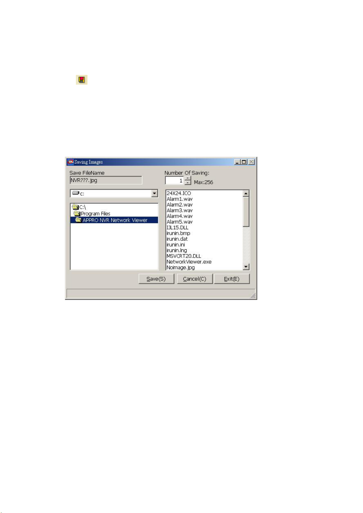
9.1.5 Archive Images to the Computer
Playback images can be stored in a local PC in the JPEG format. Follow the instructions below to save
the viewed images to your PC.
1. Press
2. Select a folder in the computer for copying images in.
3. Enter the number of images into the
4. Click the
folder. The images are saved in the NVRxxx.jpg file name, which is displayed in the box on the
right-hand side. To view a saved image, please follow the instructions in the next section to proceed.
to enter the following sample screen whenever in the playback mode.
NUMBER OF SAVING box you wish to save in.
SAVE tag; the program will automatically copy the displayed images into the designated
66
Page 69
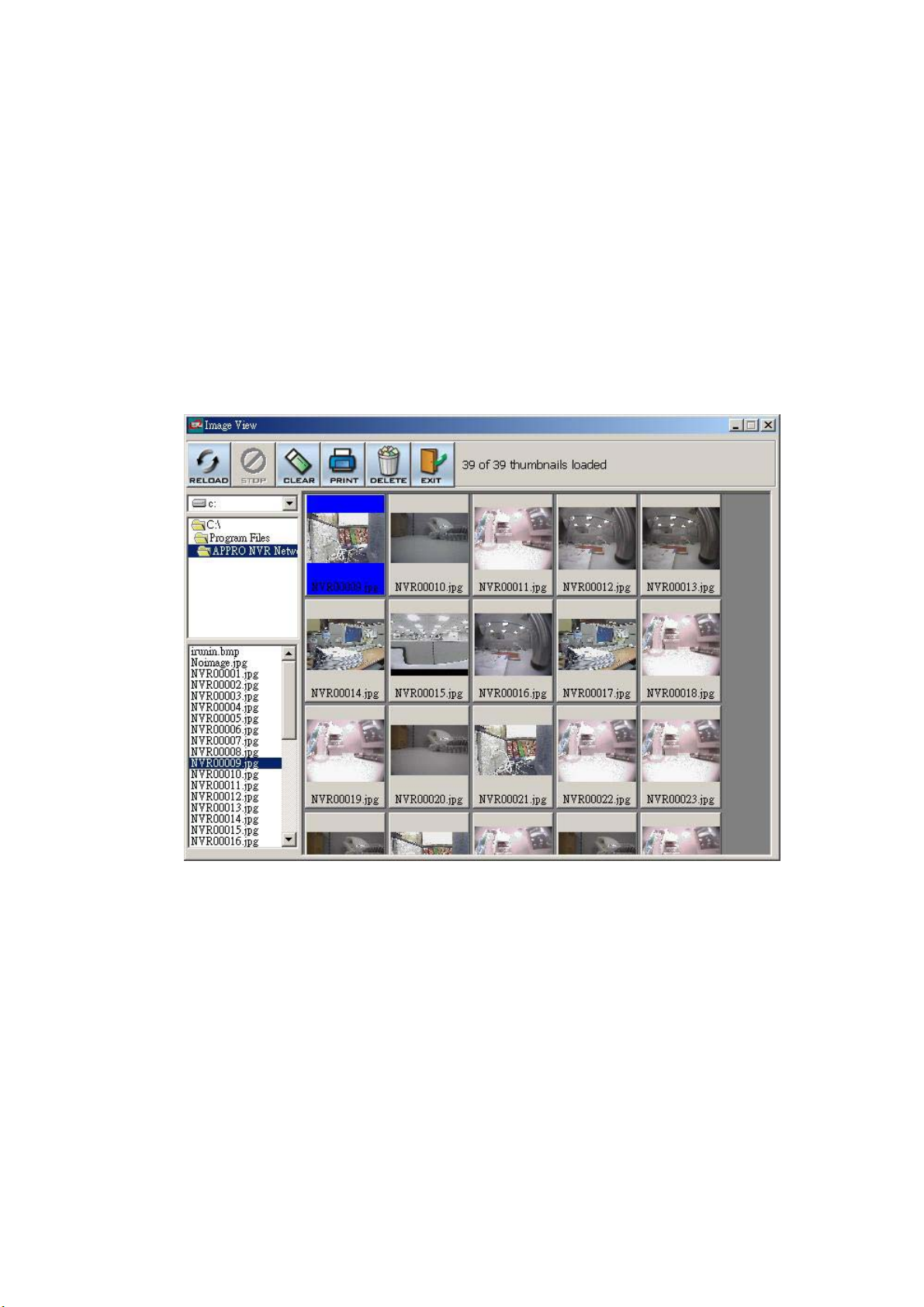
9.2 The Image Viewer
This is image integrity-protect software. It not only allows you to view an archived image from the SD
card or HDD of a computer, but also protects an archived image from reproduction or interpolation. If
an image isn’t in the original format made by a NVR, the Image Viewer won’t display the image and
instead will send a warning message”
open an archived image from a SD card or a HDD.
1. Pop up the
Network Viewer
the
Image Viewer program. (See a sample screen below.)
2. Click the
START menu from your computer, and point to Programs / APPRO NVR
to open up the program selection page. Click the Image Viewer tag to start
PRINT tag to get a displayed image printed out from a printer.
Wrong File, Can’t Open”. Follow the instructions below to
67
Page 70

10. Index Table
The following description details how the NVR manages an index table issue.
The NVR will generate a time index table indicating recorded data is kept in a particular HDD. This
allows to individually selecting recorded data to be displayed via the alarm list search and full list
search. The maximum number of lists, for a given HDD, is 3000. When the list of any given HDD is
used up-and the disk is not full, The unit will still use the rest of the space for recording. In such a
case, an index for the recent recorded data will be generated and the index of the next oldest data
will be erased so that the list does remain 3000 in total. And the next oldest data will be kept in the
index of the corresponding oldest data. For any newly-recorded data, this approach will be applied
until the disk becomes full.
3000 LISTS
In the rewrite recording mode, when the archived hard disk drive is full, the NVR will start overwriting
the oldest data recorded. As the previous recorded data was partially overwritten by the recent
recording, the indicating time index of that data will be changed corresponding to the starting time of
the remaining session. The index of the session will be deleted from the table when it is fully
overwritten.
Previously
recorded data
overwritten
HD1
1 12-02-02 12:20:55
2 12-02-02 13:30:33
3 01-30-03 16:00:34
: :
: :
:
3000 02-03-03 16:00:56
:
HD1
1 12-02-02 12:20:55
2 01-30-03 16:00:34
2999 02-03-03 16:00:56
3000 02-08-03 17:30:58
3000 LISTS
The point stops recording
Previously recorded data remaining
68
Page 71
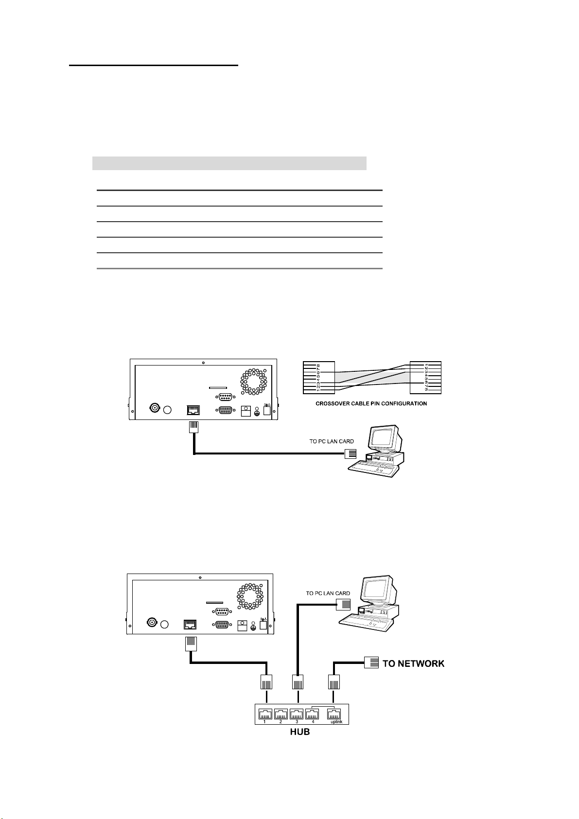
11. Network Configuration
11.1 Cable Connections
Please follow the instructions below to connect your NVR to a computer or a network and to choose a
proper RJ-45 cable configuration for connections.
Physical specification of RJ-45 cable for Ethernet
Wire Type Cat. 5
Connector Type RJ-45
Max. Cable Length 30 m
Hub Wiring Configuration Straight Through
PC Wiring Configuration Cross Over
11.1.1 Connect to a computer
Use a crossover LAN cable to connect directly to a computer.
SD Card
RJ-45
RS-232
I/O
ALARM
CROSSOVER CABLE
DC12V
ETHERNET
MONITOR AUDIO
11.1.2 Connect to a LAN Hub (INTRANET)
The RJ-45 PIN configuration for connecting with a LAN Hub is shown below.
SD Card
RJ-45
RS-232
I/O
ALARM
DC12V
ETHERNET
MONITOR AUDIO
69
Page 72
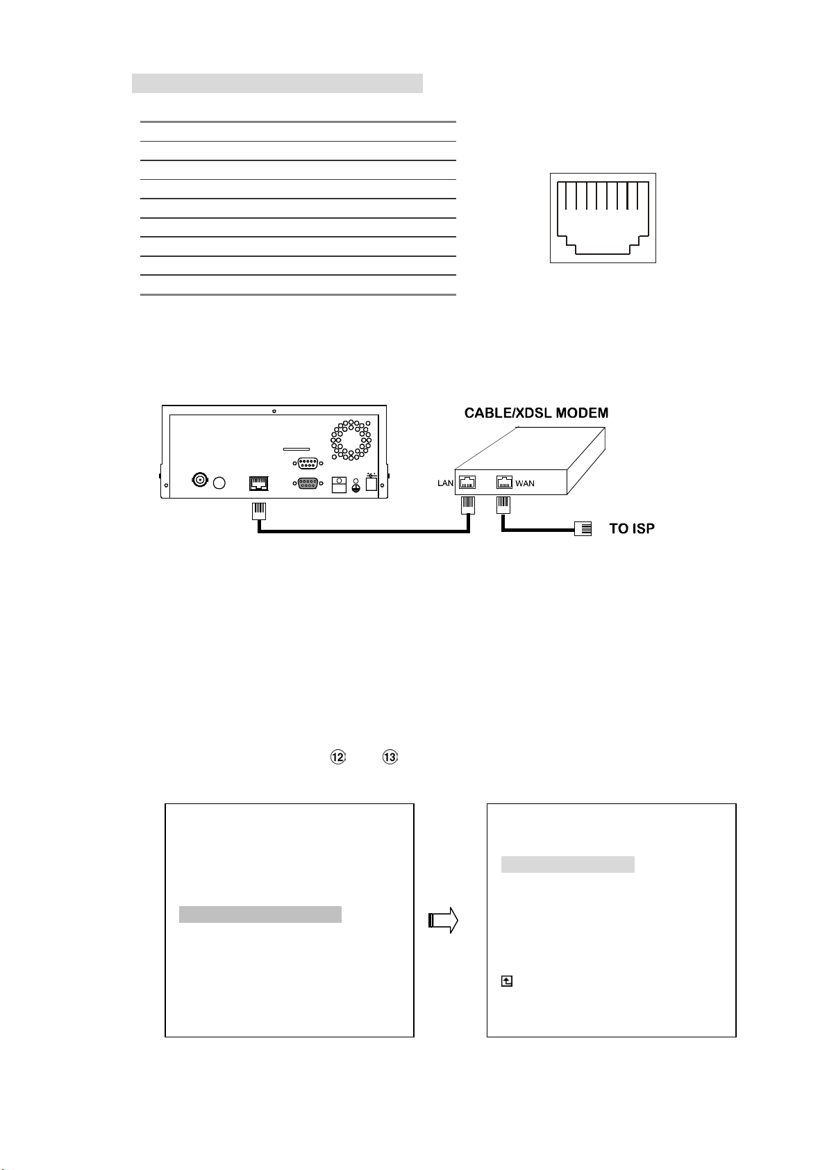
RJ-45 PIN configuration for LAN Hub
t
PIN NO. PIN Assignment
1. TX +
2. TX -
RJ-45 socke
3. RX +
4. Not Connected
5. Not Connected
1 2 3 4 5 6 7 8
6. RX -
7. Not Connected
8. Not Connected
11.1.3 Connect to WAN (INTERNET)
The RJ-45 PIN configuration for connecting to a WAN is the same as connecting to a LAN.
SD Card
RJ-45
RS-232
ALARM
I/O
DC12V
ETHERNET
MONITOR AUDIO
11.2 Configure Your NVR Network Settings
Upon network hardware connection, you need to activate the network function and configure
the proper network settings of the NVR.
11.2.1 Enable DHCP Function
Use the “^” and “v” buttons , and , to highlight NET DHCP; select ON. Then press the
Enter button to proceed.
MAIN MENU
LAN CAMERA
RECORD / BANDWIDTH
CLOCK / TIMER / SEQ
ALARM
COMMUNICATION
DISK
SYSTEM
GOTO COMM PAGE
NET IP : SET
NET DHCP : SERVER
LEASED IP TABLE : ENTER
IP POOL RANGE : SET
COMM ID : 01
RS232 : ON
MAIN PAGE
SET ETHERNET DHCP
COMM SETTING
70
Page 73
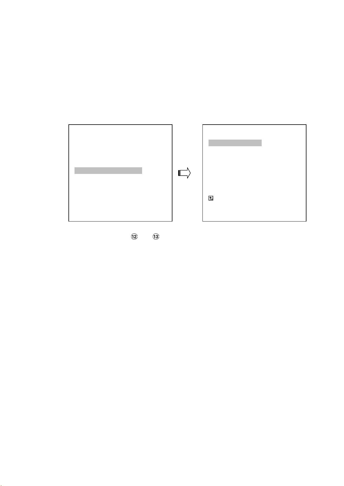
NOTE: This function can only work if the LAN which the unit is connected to has a DHCP
server. If the DHCP server is working, the NVR will obtain an IP address automatically
from the DHCP server. In that case please skip the section 11.2.2 (Set IP address) and
follow section 3. (TCP/IP Communication Software).
11.2.2 Set IP Address
You don’t need to set a NET IP for the unit if the LAN which the unit is connected to has a
DHCP server. Otherwise, please follow the instructions given below:
MAIN MENU
LAN CAMERA
RECORD / BANDWIDTH
CLOCK / TIMER / SEQ
ALARM
COMMUNICATION
DISK
SYSTEM
GOTO COMM PAGE
Use the
enter the NET IP page
“^” and “v” buttons , and , to highlight the NET IP. Press the Enter button to
NET IP : SET
NET DHCP : OFF
LEASED IP TABLE : ENTER
IP POOL RANGE : SET
COMM ID : 01
RS232 : ON
SET NETWORK
COMM SETTING
MAIN PAGE
Set the IP, MASK and GATEWAY. Then press the Enter button to proceed. The following
is a sample setting.
IP: 192.168.0.1
MASK: 255.255.255.0
GATEWAY: 0.0.0.0
NOTE: When only one unit of the NVR is connected to a computer or LAN, you can freely
assign an IP address for the NVR. For example, there is a range of NVR IP
addresses from 192.168.0.1 to 192.168.0.255. You can pick one for use from the
range of the IP. It’s not necessary to set MASK and GATEWAY; leave the settings
as default.
When a NVR is connected to a WAN, you must acquire a unique, permanent IP
address and correctly configure the MASK and GATEWAY settings according to
your network architecture. If you have any questions regarding those settings,
please contact a qualified MIS professional or your ISP.
71
Page 74
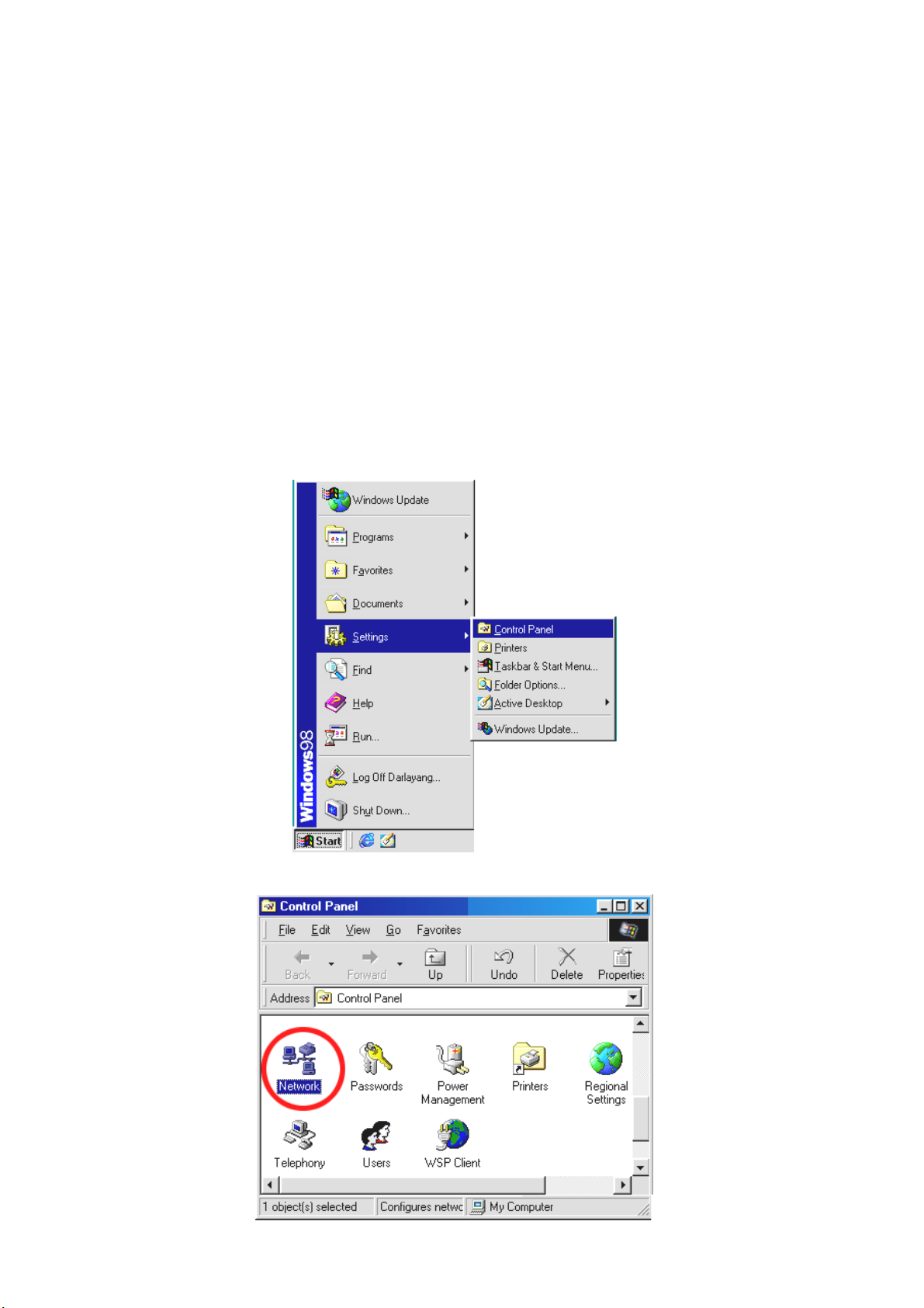
NOTE: When connecting to a network, each connected NVR must be assigned a unique
IP, which must be in the same class type as your network address. IP addresses
are written as four sets of numbers separated by periods; for example,
192.168.0.1 Therefore, if the connected network is identified as Class C, for
example, the first three sets of numbers of the NVR IP address must be the same
as the network address. If the connected network is identified as Class B, the
first two sets of numbers of the NVR IP address must be the same as the network
address. If you have any questions regarding these settings, please contact a
qualified MIS professional or your ISP.
11.3 TCP/IP Communication Software
Follow the instructions below to install the TCP/IP communication program into your computer.
Click the Start Menu from your computer, and point to the Settings/Control panel.
Click the NETWORK icon twice to enter the NETWORK setting windows.
72
Page 75
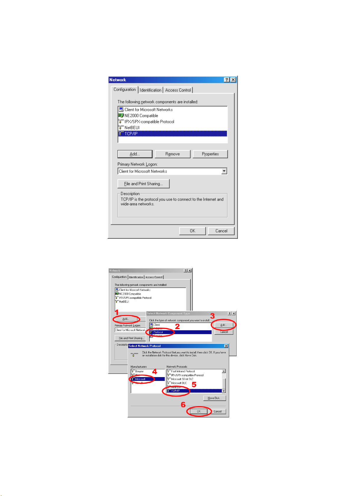
Click on the Configuration tag; check if the TCP/IC is included among the network
components list. If the TCP/IP is included, please process step 5. If it is not included,
please follow step 4 to install the TCP/IP.
11.4 TCP/IP installation
During the installation, you will be requested to insert the windows 98 CD ROM. After
installation, the PC will be restarted.
73
Page 76
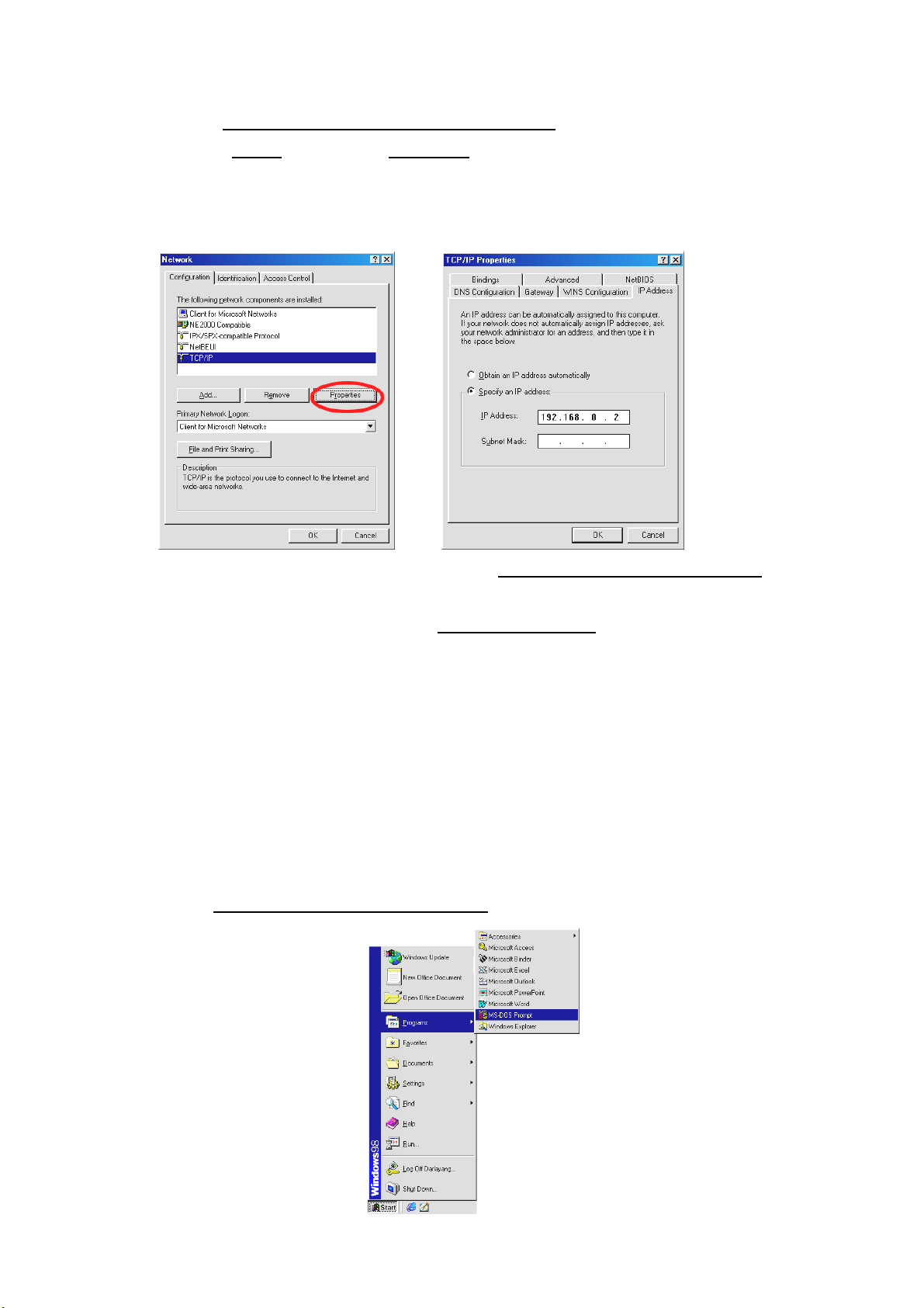
11.5 TCP/IP Configuration setting
Click Start Settings Control Panel Network.
Select TCP/IP, and then click Properties.
Before processing the NVR installation in a WAN, please make sure the Internet
connection works properly. If not, please contact your ISP provider.
If you are using a DHCP server, please select Obtain an IP address automatically. Any
assigned IP address for the connected NVRs must be in the same class type as the server. If
there is no DHCP server, please select
your PC. This IP address must be different from the NVR IP but in the same class type.
NOTE: The IP address of a NVR in a network must be unique to itself as opposed to
those of the other chosen PCs, but in the same class type
specify an IP address and type in the IP address of
11.6 Connection Testing
With the previous settings, follow the instructions below to ensure whether you have established
the connection successfully.
Click Start Programs MS-DOS Prompt
74
Page 77
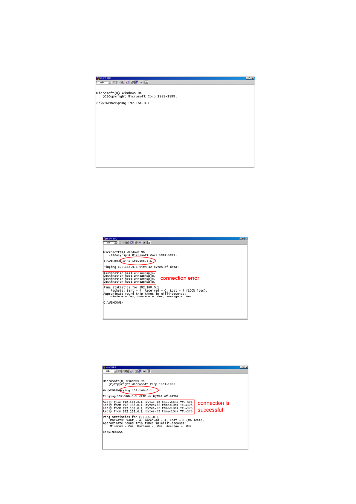
Type in ping 192.168.0.1 then Enter. (See the sample screen below)
**
This IP is the NVR IP address that is assigned for the connected NVR in step 2.
If you receive a response as in the sample screen below, the connection hasn’t been
successfully established. Please re-check all the hardware and software installation by
repeating steps 1 to 5. If you still can’t establish the connection after rechecking, please
contact your dealer.
If you receive a response as in the sample screen below, you have successfully made the
connection.
75
Page 78
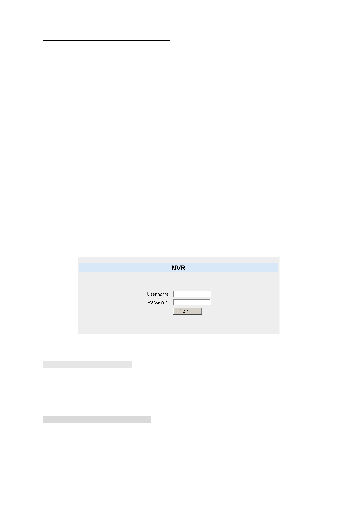
12. Microsoft Internet Explorer
This section provides instructions for using the Microsoft Internet Explorer, which are included with
the NVR-2018.
12.1 Connecting the NVR-2018
Start up the Microsoft Internet Explorer, and then follow the steps given below to connect the
NVR-2018:
1. Click the URL block at the top of the screen.
2. Type in the URL address of the NVR-2018 into the URL block and press the “
to enter the login page. The default User Name and password is
respectively.
3. Enter the user name (Login Name).
4. Fill in the password (Password).
5. Click the “
and password must be provided correctly.
Login” button and enter the home page of the NVR-2018: both the user name
Enter” button
admin and 9999
Description of functional keys:
Login Name:
Password: Fill in the password in the blank space.
Login: Click to enter the home page of the NVR-2018.
Browsing images from the NVR-2018:
The images from the NVR-2018 will be displayed on the home page while going online with the
NVR-2018. There are some buttons provided on the bottom of the home page for further
setting:
Enter the user name in the blank space.
76
Page 79
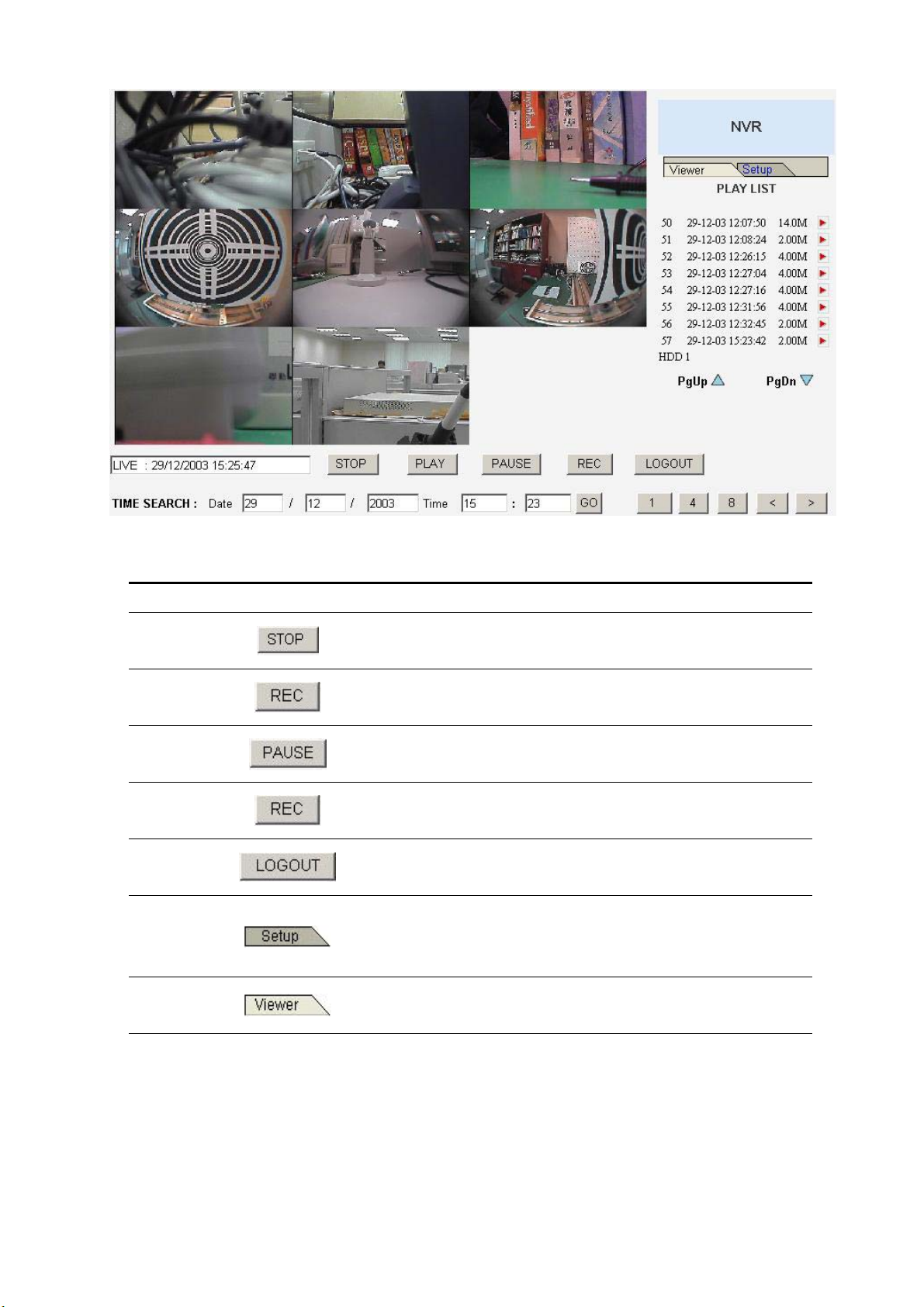
Function Buttons
Description
Click to stop playing back the recorded video or to
cease recording.
Click to a recorded video from the PLAY LIST.
Click to freeze the image.
Click to activate the recording function of the device.
Click to leave the home page of the NVR-2018.
Press to enter the SETUP window, and open the
device setting page in order to add more devices for
viewing. This allows you to program the Record
Setting and Record Schedule.
Press to enter the IMAGE window and open the
device home page for viewing.
77
Page 80
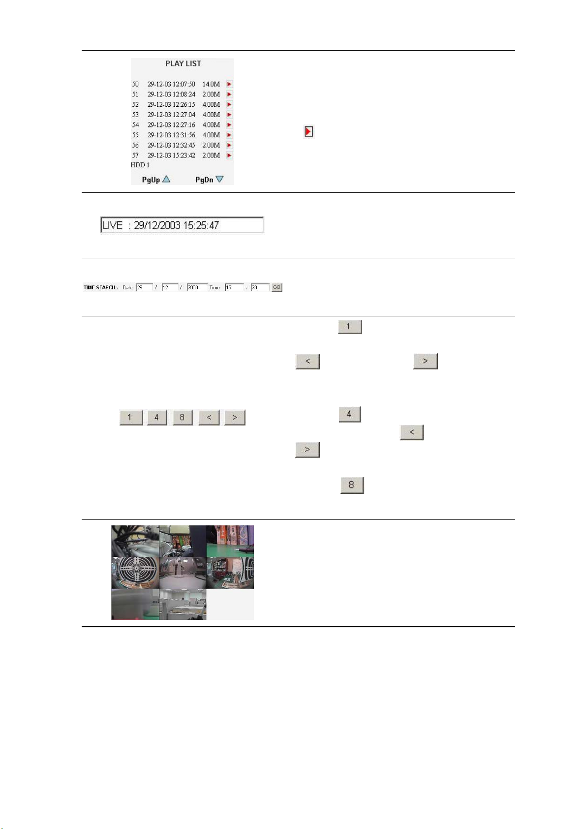
Recorded video list box. This box allows you to
access all recorded video, which are stored in the
HDD of the connected devices. To review a recorded
video, simply select an entry from the list and click
the
PgUp/PgDn: Enables you to scroll up and down the
button.
list.
NVR-2018 Time & Status Box. This box indicates the
selected device status.
PLAY: The device is in the playback mode.
LIVE: The device enters the live display mode.
This allows you to search a recorded video stored in
the HDD of the device. Enter the
YEAR/MONTH/DAY HOUR: MINUTE you wish to
search and click the GO button to proceed.
Click the button to see images in the single
channel mode. Channel 1 is the default. Click the
(left) button or the (right) button to
view images in the next channels in either the
forward or the reverse directions.
Click the button to see images in the quad
mode. Use either the
(left) button or the
(right) button to view the next four channels
in either the forward or the reverse directions.
Click the button to view images in the 8
channel mode.
Image display area. Displays images from the 8ch
cameras.
78
Page 81
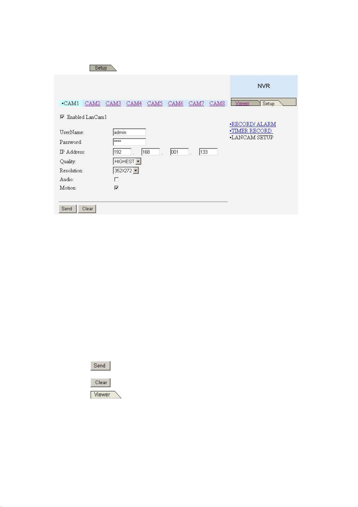
12.2 Change LANCAM SETUP Setting
Please follow the steps given below to change the LANCAM setting through the network as and
when necessary.
(1) Click the
(2) At the top of the page are itemized CAMs 1 to 8, each of which is connected to the
corresponding camera. So, if you click any of them, the corresponding camera’s information
will appear in the blank spaces of all the items on the screen.
button on the home page to enter the setup mode.
(3) Adjust the LANCAM setup, including all the items on the screen given below:
Enabled LanCam
UserName
Password
IP Address
Quality
Resolution
Audio
Motion
The information in all the above items’ attached spaces can be sent to the NVR.
(4) Click the
(5) Click the
(6) Click the
the images to effect the desired changes instantly. (If the setting has not been changed by
the above steps, any (re)entry onto the home page will find images in their earlier or original
button to submit the new LANCAM setting.
button to delete all information given against all the items on the screen.
button to return to the home page while the new image setting acts on
setting. )
79
Page 82
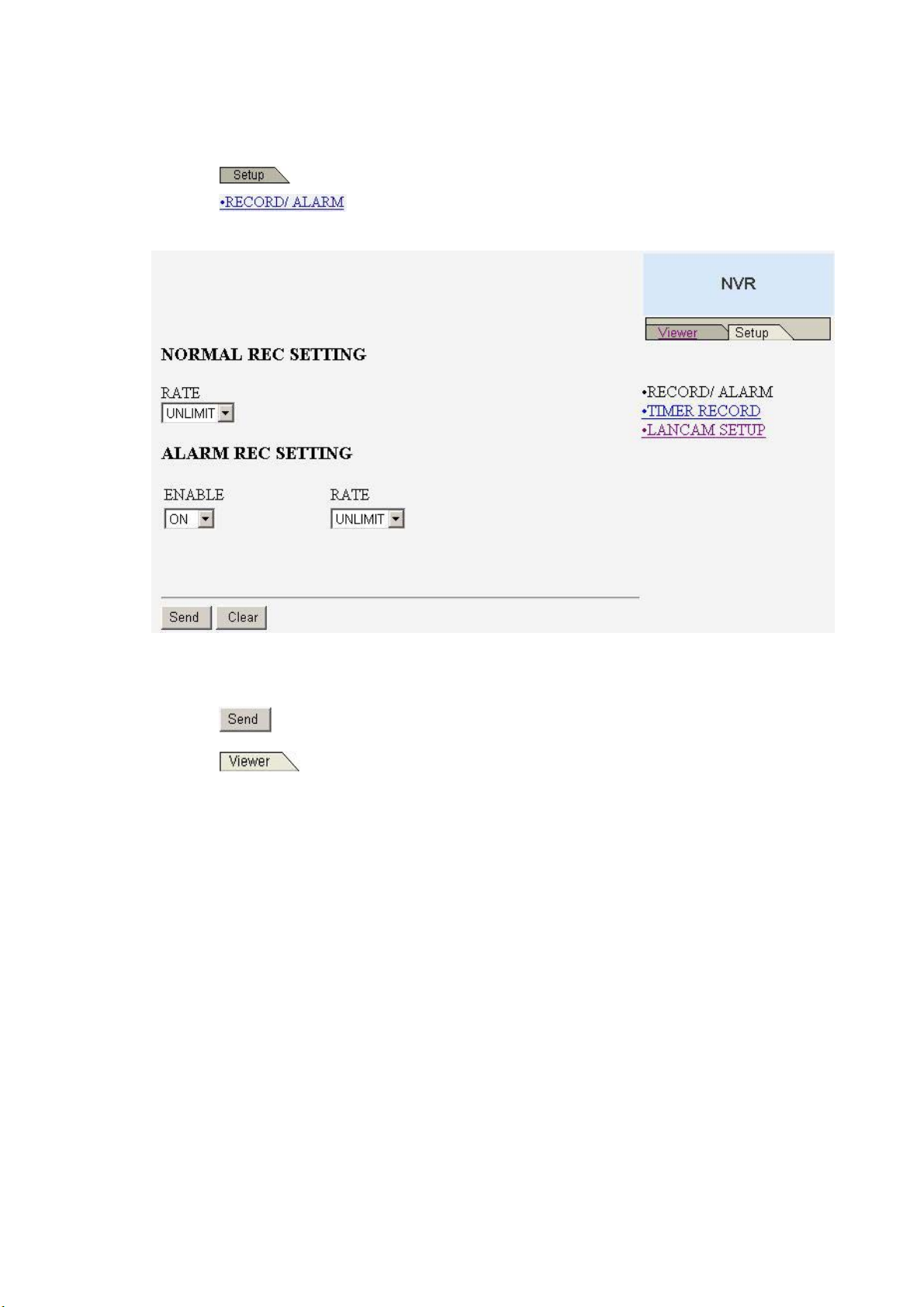
12.3 Change Record / Alarm Setting
Please follow the steps given below to change the RECORD / ALARM setting through the network
as and when necessary.
1. Click the
2. Click the
setting page.
3. Adjust the Record / Alarm setting, including the “NORMAL REC SETTING RATE”, “ALARM
button on the home page to enter the setup mode.
connection on the setting page to enter the RECORD / ALARM
REC SETTING ENABLE”, and “ALARM REC SETTING RATE” as and when necessary.
4. Click the
5. Click the
images to effect the desired changes instantly. (If the setting has not been changed by the
above steps, any (re)entry onto the home page will find images in their earlier or original
setting. )
button to submit the new Record / Alarm setting.
button to return to the home page while the new image setting acts on the
80
Page 83
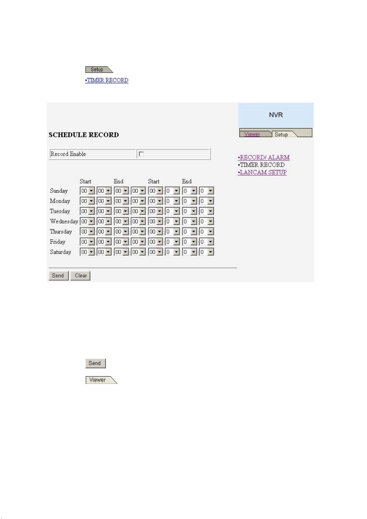
12.4 Change Timer Record Setting
Please follow the steps below to change the Timer Record setting through the network as and when
necessary.
1. Click the
2. Click the
page.
button on the home page to enter the setup mode.
connection on the setting page to enter the Timer Record setting
3. Set the
4. There are two time-periods available for scheduling each day. The Timer Record setting page
allows users to program the time each day that the NVR-2018 will start and stop recording. The
time is displayed in a 24-hour clock format. If there is a time overlap showing between two
continual time-period settings, the device will automatically combine the two time-period
settings into one combined time-period setting.
5. Click the
6. Click the
the images to effect the desired changes instantly. (If the setting has not been changed by
the above steps, any (re)entry onto the home page will find images in their earlier or original
setting. )
SCHEDULE RECORD to ON to enable the SCHEDULE RECORD function.
button to submit the new Timer Record setting.
button to return to the home page while the new image setting acts on
81
Page 84

13. SPECIFICATIONS
Model Number 8CH NVR-2018
Lancam Connection Lancam x 8
Image System NTSC PAL
Image Resolution
Video Input interface RJ-45 (bit stream from Lancam)
Video Out Mon1 (BNC)
Audio Input interface RJ-45 (bit stream from Lancam)
Audio Out RCA x 1
Compression MJPEG
Storage Media > 320 GB / 1 Fixed HDD, 1 Removable HDD
Memory Card SD Card
Archive Hot Swappable Removable HD
Watermark Digital Signature
Max Recording Rate
Image Size 4 ~ 64 KB
Recording Mode Schedule / Manual / Alarm / Circular
Alarm Recording Motion / Event(image) / Pre-Alarm / Post Alarm
Max Pre-Alarm Recording 256 Pictures
Playback Speeds Frame Stepping, 1/32x,1/16x,1/8x,1/4x,1/2x,1x,2x,4x,8x,16x,32x,100x
Record Search Alarm / Time / Filter(thumbnail) / SD card
OSD Language English / Chinese(T)
Set-up Menu Multi-layer / Network setting
Log list 2048 records
Alarm In/Out 1 Alarm Output
Built-in Buzzer Yes
Motion Detection Yes
Communication Port RS-232 and Ethernet Port
Network Interface Ethernet (RJ-45 10/100 base-Tx) x 1
Network Protocol TCP/IP, DHCP, HTTP, UDP, ARP, ICMP
Software Upgrade Upgrade via Memory Card(SD Card)
Password Protection Menu Setup / Remote Access / Format HDD
Network Capabilities
Power Supply (AC adapter) Input: 100V-240V, 50 Hz/60 Hz; Output: DC12V max 5A
Dimensions 220 mm x 94 mm x 340 mm EIA 19" 2U Half Size Mountable
Weight About 3.9 kg (without HDD)
Operation Temperature 5∘C ~ 40∘C (41∘F ~ 104∘F)
Regulation FCC, CE
Provided Accessories
720 x 480 pixels
352 x 240 pixels
20 ips (720x480)
50
ips (352x240)
Archive image as JPEG formats,
Remote system setup and control
View live or recorded images
AC Adapter x 1
Instruction manual x 1
Power cord x 1
CD-R x 1
Screw ( #6-32UNC ) x 4, Screw ( M3 ) x 8(not in use)
Mobile Rack Key x 2
720 x 576 pixels
352 x 288 pixels
ips (720x576)
20
50
ips (352x288)
*Design and specifications subject to change without notice.
82
Page 85
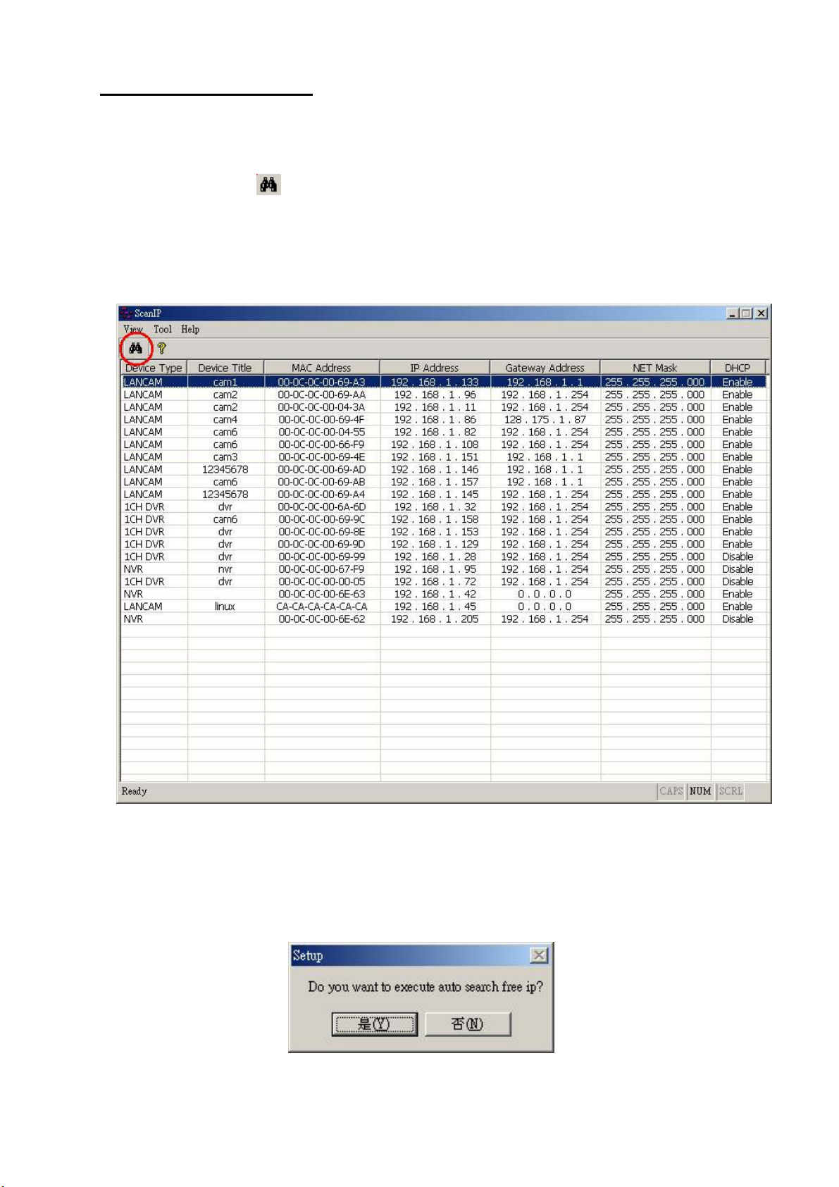
APPENDIX 1. –SCANIP
Follow the instructions below to use the SCANIP software to search the NVR devices from a local
location.
1. Click the
Device List will display the connection of the all-type device.
2. Select the desired device from the
3. Click the desired device to show the window while the NVR information acts to
display the desired changes instantly.
button to discover the connection of the all-type device in the LAN. The
Device List.
4. Do you want to execute auto search free IP?
If and when you want to auto search the free IP, select “Yes” or “No”. If clicked “Yes” the
software will provide the “Free IP Address” boxes on the right side of the window. If you click
“No”, these address boxes will not show.
83
Page 86
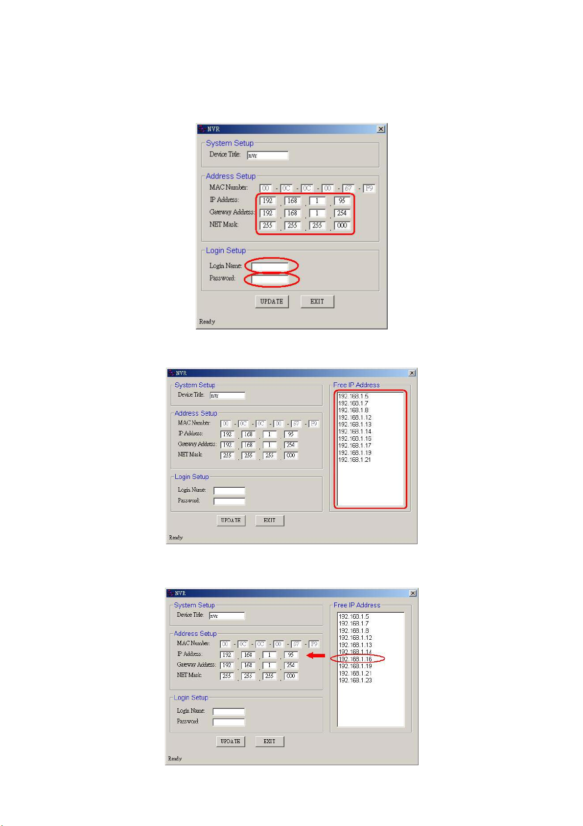
5. Manual insertion of “Free IP Address”.
If you have clicked “No”, please manually type in insertions as required in the “Free IP
Address”, “Gateway Address”, and “NET Mask”. Follow each insertion you make by typing in
the “Login Name” and “Password”, and click “UPDATE” to send your alterations to the NVR.
6. Auto search “Free IP Address”.
If you clicked “Yes” the “Free IP Address” box will appear on the right.
7. Select and double click any of the addresses in the “Free IP Address” box on the right to
enter it into an IP Address on the left.
84
Page 87
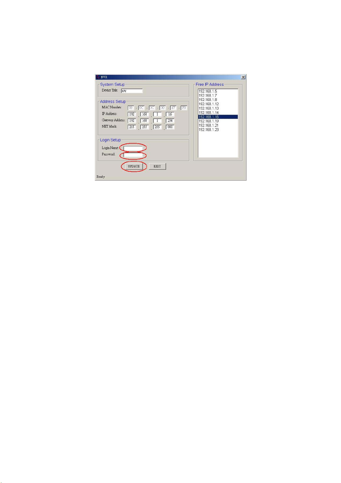
8. To change any IP address, type in the new address in the “Free IP Address” box on the right
as well as the device “Login Name” and “Password” in their respective blanks at bottom left,
then click “UPDATE”, and the new address will automatically be sent to the device.
9. Click “Exit” at bottom right to shut the device.
RMN040200230_V2.2
85
 Loading...