

Page 1
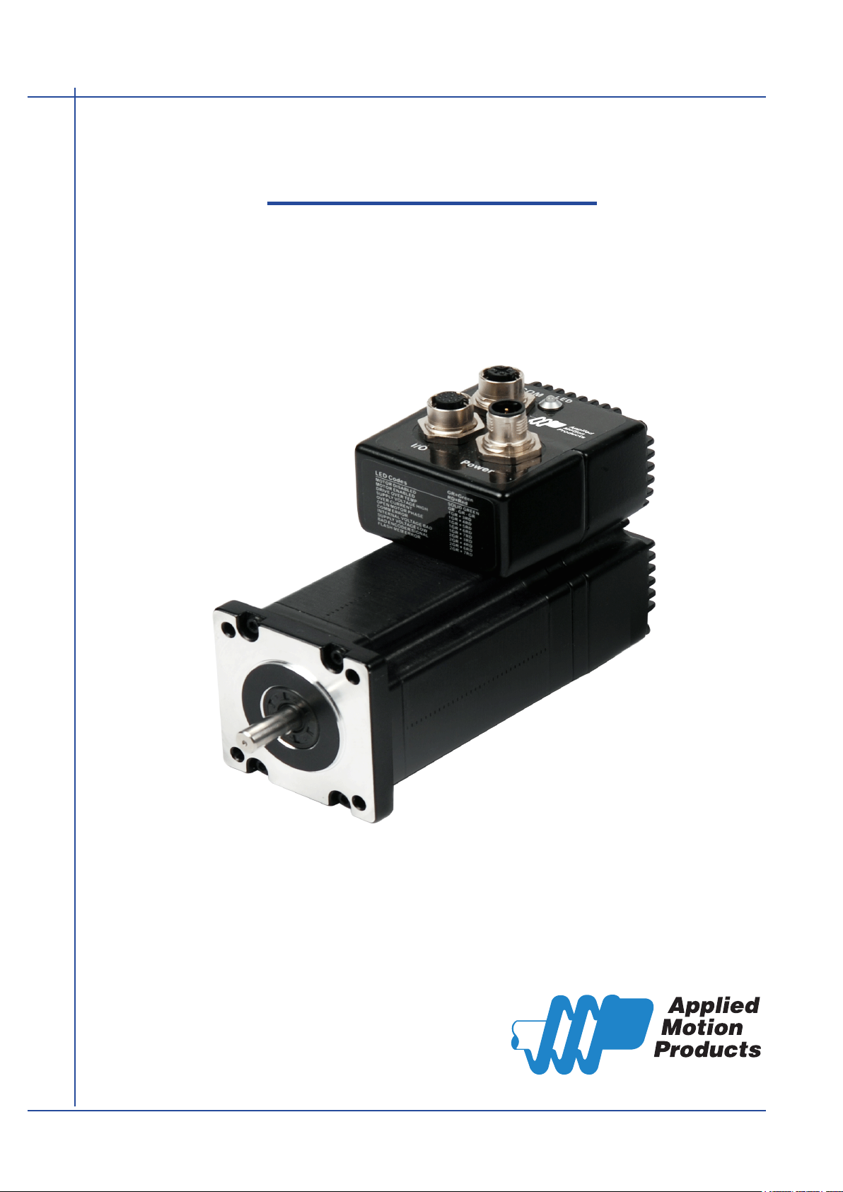
TXM24 Ethernet
Integrated Step-Servo Motor
Hardware Manual
920-0089
Rev. C
Page 2

TXM24 Ethernet Hardware Manual
Contents
1 Introduction ................................................................................................................... 3
1.1 Features ............................................................................................................3
1.2 Block Diagram ................................................................................................... 4
1.3 Safety Instructions ............................................................................................. 5
2 Getting Started ..............................................................................................................6
2.1 Installing Software ............................................................................................. 6
2.2 Mounting the Hardware ..................................................................................... 6
2.3 Choosing a Power Supply ................................................................................. 7
2.3.1 Voltage .............................................................................................7
2.3.2 Regeneration Clamp .........................................................................7
2.3.3 Current ..............................................................................................8
3 Installation/Connections................................................................................................11
3.1 Connecting the Power Supply ........................................................................... 11
3.2 Connecting the TXM24 Communications .......................................................... 12
3.2.1 Connecting to the PC using Ethernet ................................................ 12
3.3 Connecting the Drive to Your PC using Ethernet ..............................................13
3.3.1 Addresses, Subnets, and Ports .........................................................13
3.3.2 Option 1: Connect a Drive to Your Local Area Network .....................14
3.3.3 Option 2: Connect a Drive Directly to Your PC ..................................15
3.3.4 Option 3: Use Two Network Interface Cards (NICs) .......................... 16
3.4 Inputs and Outputs ............................................................................................ 17
3.4.1 Connector Pin Diagram ..................................................................... 17
3.4.2 STEP & DIR Digital Inputs ................................................................. 18
3.4.3 EN Digital Input .................................................................................19
3.4.4 AIN Input ............................................................................................20
3.4.5 Programmable Output ....................................................................... 21
4 Troubleshooting ............................................................................................................22
5 Reference Materials ......................................................................................................23
5.1 Torque-Speed Curves .......................................................................................23
5.2 Mechanical Outlines .......................................................................................... 24
5.3 Technical Specications ....................................................................................25
5.4 Accessories ....................................................................................................... 26
6 Contacting Applied Motion Products .............................................................................26
Rev. C
920-0089
2
Page 3

TXM24 Ethernet Hardware Manual
1 Introduction
Thank you for selecting the Applied Motion Products TXM24 Integrated
Motor.The TXM line of integrated step-servo motors combines servo
technology with an integrated motor to create a product with exceptional
feature and broad capability. We hope our commitment to performance,
quality and economy will result in a successful motion control project.
1.1 Features
• Programmable, Digital servo driver and motor in an integrated
package
• Operates from a 12 to 70 volt DC power supply
• Control Modes:
Torque Control
* Analog input
* SCL commanded
Velocity Control
* Digital input Control Velocity
* Analog velocity
* SCL Commanded Velocity (Jogging)
Position Control
* Digital Signal type
• Step & Direction
• CW & CCW pulse
• A/B Quadrature (Encoder Following)
* Analog Position
* Serial Commanded Position
Q Programming(Q Verision only)
* Stand alone operation
• Communications:
* Ethernet UDP/TCP, EtherNet/IP
• 5000 line (20,000 counts/rev) encoder feedback
• Available torque:
* TXM24S/Q/IP-3EG: Up to 2.4N•m Continuous (3.0 N•m Boost)
* TXM24S/Q/IP-1EG: Up to 0.82N•m Continuous (1.03N•m Boost)
• I/O:
3 optically isolated digital inputs, with adjustable bandwidth digital noise rejection lter, 5
to 24 volts
1 optically isolated digital output, 30V/100 mA max.
1 analog input for speed and position control, 0 to 5 volts
• Technological advances:
Full servo control, Closed loop
Efcient, Accurate, Fast, Smooth
Intelligent, Compact
• IP65 protected with three M12 connectors.
3
Rev. C
920-0089
Page 4
TXM24 Ethernet Hardware Manual
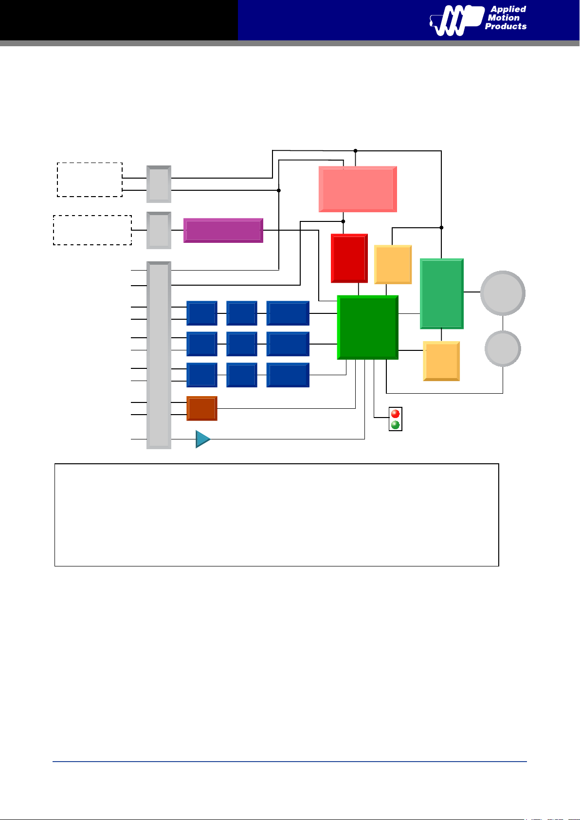
1.2 Block Diagram
TXM24 Ethernet
Block Diagram
12 - 70 VDC
External
Power Supply
Ethernet
TX+,TX-,RX+,RX-
GND
+5V
STEP+
STEP-
DIR+
DIR-
EN+
EN-
OUT+
OUT-
AIN
+
-
Conn
Power
Conn
Comm
Ethernet
GND
+5VDC (100mA max)
Optical
Iso
Digital
Filter
Software
Filter
5 Volt DC
Power Supply
3.3VDC
Internal
Logic
Supply
DSP
Voltage
Temp
Detect
MOSFET
PWM
Power
Amplifier
motor
Driver
Optical
Iso
Optical
I/O Connector
Iso
Optical
Iso
Digital
Filter
Digital
Filter
Software
Filter
Software
Filter
Controller
Status
Over
Current
Detect
encoder
I/O Configurations
STEP (5 to 24 volts)
Step
CW step
A quadrature (encoder following)
CW limit
CW jog
Start/stop (oscillator mode)
General purpose input
DIR (5 to 24 volts)
Direction
CCW step
B quadrature (encoder following)
CCW limit
CCW jog
Direction (oscillator mode)
General purpose input
EN (5 to 24 volts)
Enable
Alarm/fault reset
Speed 1/speed 2 (oscillator mode)
General purpose input
OUT (30V, 100mA)
Fault
Motion
Tach
In position
Brake
General purpose programmable
Rev. C
920-0089
4
Page 5

TXM24 Ethernet Hardware Manual
1.3 Safety Instructions
Only qualied personnel should transport, assemble, install, operate, or maintain this equipment.
Properly qualied personnel are persons who are familiar with the transport, assembly, installation,
operation, and maintenance of motors, and who meet the appropriate qualications for their jobs.
To minimize the risk of potential safety problems, all applicable local and national codes regulating
the installation and operation of equipment should be followed. These codes may vary from area
to area and it is the responsibility of the operating personnel to determine which codes should be
followed, and to verify that the equipment, installation, and operation are in compliance with the
latest revision of these codes.
Equipment damage or serious injury to personnel can result from the failure to follow all applicable
codes and standards. Applied Motion Products does not guarantee the products described in
this publication are suitable for a particular application, nor do they assume any responsibility for
product design, installation, or operation.
• Read all available documentation before assembly and operation. Incorrect handling of the
products referenced in this manual can result in injury and damage to persons and machinery.
All technical information concerning the installation requirements must be strictly adhered to.
• It is vital to ensure that all system components are connected to earth ground. Electrical safety
is impossible without a low-resistance earth connection.
• This product contains electrostatically sensitive components that can be damaged by incorrect
handling. Follow qualied anti-static procedures before touching the product.
• During operation keep all covers and cabinet doors shut to avoid any hazards that could
possibly cause severe damage to the product or personal health.
• During operation, the product may have components that are live or have hot surfaces.
• Never plug in or unplug the Integrated Motor while the system is live. The possibility of electric
arcing can cause damage.
Be alert to the potential for personal injury. Follow recommended precautions and safe operating
practices emphasized with alert symbols. Safety notices in this manual provide important
information. Read and be familiar with these instructions before attempting installation, operation,
or maintenance. The purpose of this section is to alert users to the possible safety hazards
associated with this equipment and the precautions necessary to reduce the risk of personal injury
and damage to equipment. Failure to observe these precautions could result in serious bodily
injury, damage to the equipment, or operational difculty.
5
Rev. C
920-0089
Page 6

TXM24 Ethernet Hardware Manual
2 Getting Started
The following items are needed:
• a 12 - 70 volt DC power supply, see the section below entitled “Choosing a Power Supply” for
help in choosing the right one
• a PC running Microsoft Windows XP, Vista, or Windows 7 or 8
2.1 Installing Software
Before utilizing the TXM24 Integrated Step-Servo Motor and Step-Servo Quick Tuner Software in
an application, the following steps are necessary:
• Download and install the Step-Servo Quick Tuner software from Applied Motion Products
website.
• Connect the drive to the PC using the Ethernet communication cable.
• Connect the drive to the power supply. See instructions below.
• Launch the software by clicking Start...Programs...Applied Motion Products...Step-Servo Quick
Tuner
• Apply power to the drive.
2.2 Mounting the Hardware
As with any step motor, the TXM24 must be mounted so as to provide maximum heat sinking and
airow. Keep enough space around the Integrated Motor to allow for airow.
• Never use the drive where there is no airow or where other devices cause
the surrounding air to be more than 40°C (104°F).
• Never put the drive where it can get wet.
• Never use the drive where metal or other electrically conductive particles can
inltrate the drive.
• Always provide airow around the drive.
Rev. C
920-0089
6
Page 7
TXM24 Ethernet Hardware Manual
2.3 Choosing a Power Supply
The main considerations when choosing a power supply are the voltage and current requirements
for the application.
2.3.1 Voltage
The TXM24 is designed to give optimum performance between 24 and 48 Volts DC. Choosing the
voltage depends on the performance needed and motor/drive heating that is acceptable and/or
does not cause a drive over-temperature. Higher voltages will give higher speed performance but
will cause the TXM24 to produce higher temperatures. Using power supplies with voltage outputs
that are near the drive maximum may signicantly reduce the operational duty-cycle.
The extended range of operation can be as low as 10 VDC minimum to as high as 75 VDC
maximum. When operating below 18 VDC, the power supply input may require larger capacitance
to prevent under-voltage and internal-supply alarms. Current spikes may make supply readings
erratic. The supply input cannot go below 10 VDC for reliable operation. Absolute minimum power
supply input is 10 VDC. If the Input supply drops below 10 VDC the low voltage alarm will be
triggered. This will not fault the drive.
Absolute maximum power supply input is 75 VDC at which point an over-voltage alarm and fault
will occur. When using a power supply that is regulated and is near the drive maximum voltage
of 75 VDC, a voltage clamp may be required to prevent over-voltage when regeneration occurs.
When using an unregulated power supply, make sure the no-load voltage of the supply does not
exceed the drive’s maximum input voltage of 75 VDC.
2.3.2 Regeneration Clamp
If a regulated power supply is being used, there may be a problem with regeneration. When a load
decelerates rapidly from a high speed, some of the kinetic energy of the load is transferred back to
the power supply, possibly tripping the over-voltage protection of a regulated power supply,
causing it to shut down. This problem can be solved with the use of an Applied Motion Products
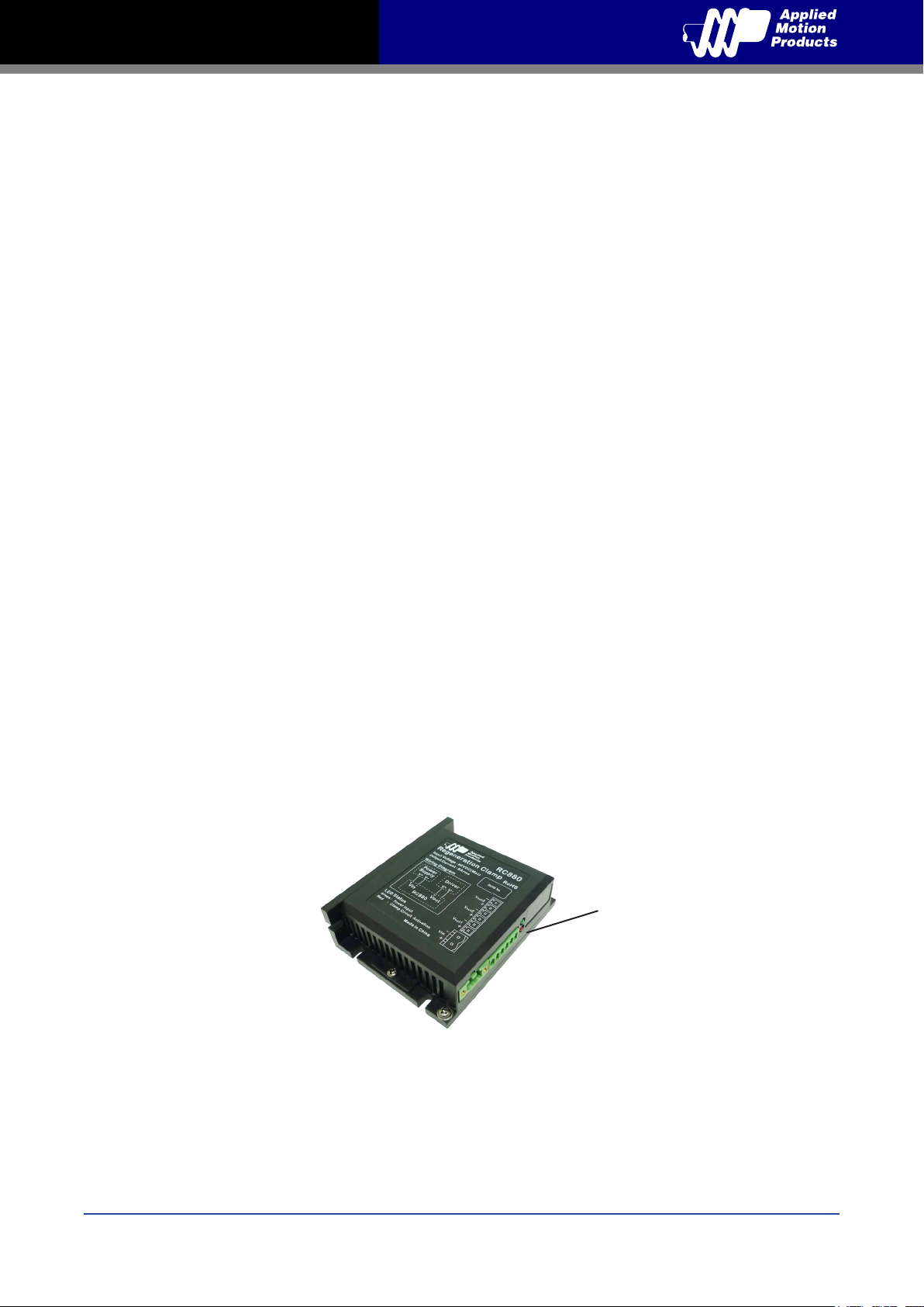
RC880 Regeneration Clamp. It is recommended that an RC880 initially be installed in an
application. If the “regen” LED on the RC880 never ashes, the clamp is not necessary.
LEDs
Green - Power
Red - Regen on
RC880 Regen Clamp
7
Rev. C
920-0089
Page 8
TXM24 Ethernet Hardware Manual
2.3.3 Current
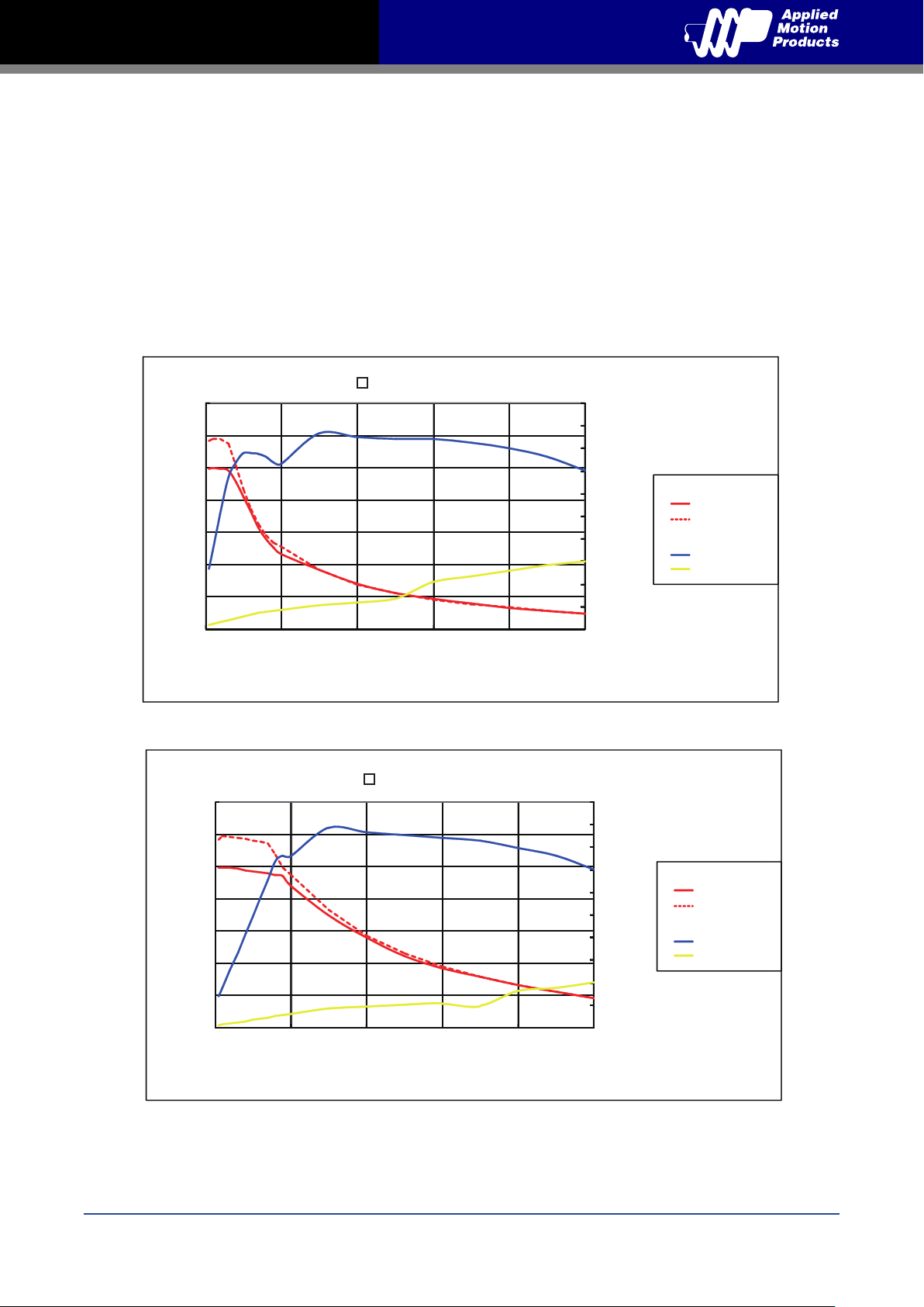
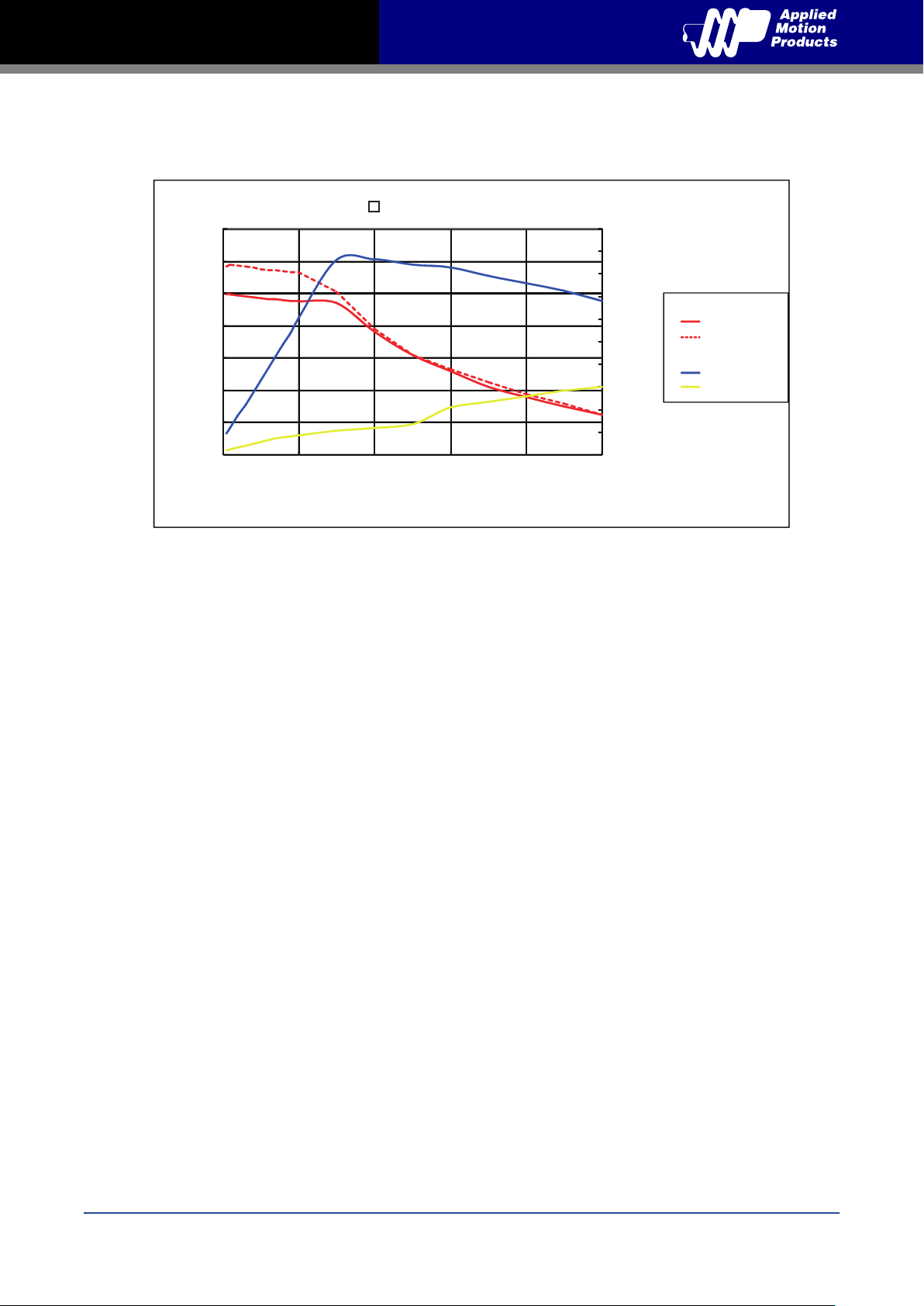
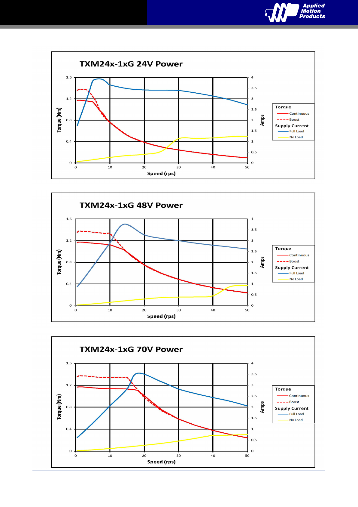
The maximum supply currents required by the TXM24 are shown in the charts below at different
power supply voltage inputs. The TXM24 power supply current is lower than the winding currents
because it uses switching ampliers to convert a high voltage and low current into lower voltage
and higher current. The more the power supply voltage exceeds the motor voltage, the less
current will be required from the power supply.
It is important to note that the current draw is signicantly different at higher speeds depending
on the torque load to the motor. Estimating how much current is necessary may require a good
analysis of the load the motor will encounter.
TXM24□-3EG 24V Power
3.5
3
2.5
2
1.5
1
Torque(N.m)
0.5
0
0 10 20 30 40 50
Speed(RPS)
5
4.5
4
3.5
3
2.5
2
1.5
1
0.5
0
Torque
Supply Current
Amps
Continuous
Boost
Full Load
No Load
TXM24□-3EG 48V Power
3.5
3
2.5
2
1.5
Torque(N.m)
1
0.5
0
0 10 20 30 40 50
Speed(RPS)
5
4.5
4
3.5
3
2.5
2
1.5
1
0.5
0
Torque
Supply Current
Amps
Continuous
Boost
Full Load
No Load
Rev. C
920-0089
8
Page 9
TXM24 Ethernet Hardware Manual
TXM24□-3EG 70V Power
3.5
3
2.5
2
1.5
1
Torque(N.m)
0.5
0
0 10 20 30 40 50
Speed(RPS)
5
4.5
4
3.5
3
2.5
2
1.5
1
0.5
0
Torque
Supply Current
Amps
Continuous
Boost
Full Load
No Load
9
Rev. C
920-0089
Page 10
TXM24 Ethernet Hardware Manual
Rev. C
920-0089
10
Page 11
TXM24 Ethernet Hardware Manual
3
4
3 Installation/Connections
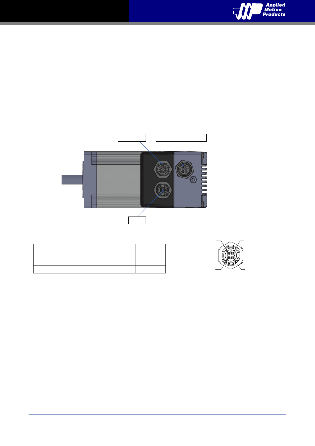
To meeting the IP65 protection, a suitable mating connector should be chosen.
For more information, please see the Accessories section.
3.1 Connecting the Power Supply
Use 16 to 20-gauge wire to connect the TXM24 to a power supply. It contains an internal fuse
connected to the “+” terminal that is not user replaceable. If a user serviceable fuse is desired,
install a 6.3 amp fast acting fuse in line with the “+” power supply lead.
Be careful not to reverse the wires. Reversing the connection may open the internal fuse on the
drive and void the warranty.
Digital I/O
Power
Signal
V+ BN\BU 1\3
V- WH\BK 2\4
Color of mating cable
Phoenix P/N 1431678
Power
Ethernet COMM port1
Pin no.
2
1
J2
View of motor side connector
11
Rev. C
920-0089
Page 12
TXM24 Ethernet Hardware Manual
3.2 Connecting the TXM24 Communications
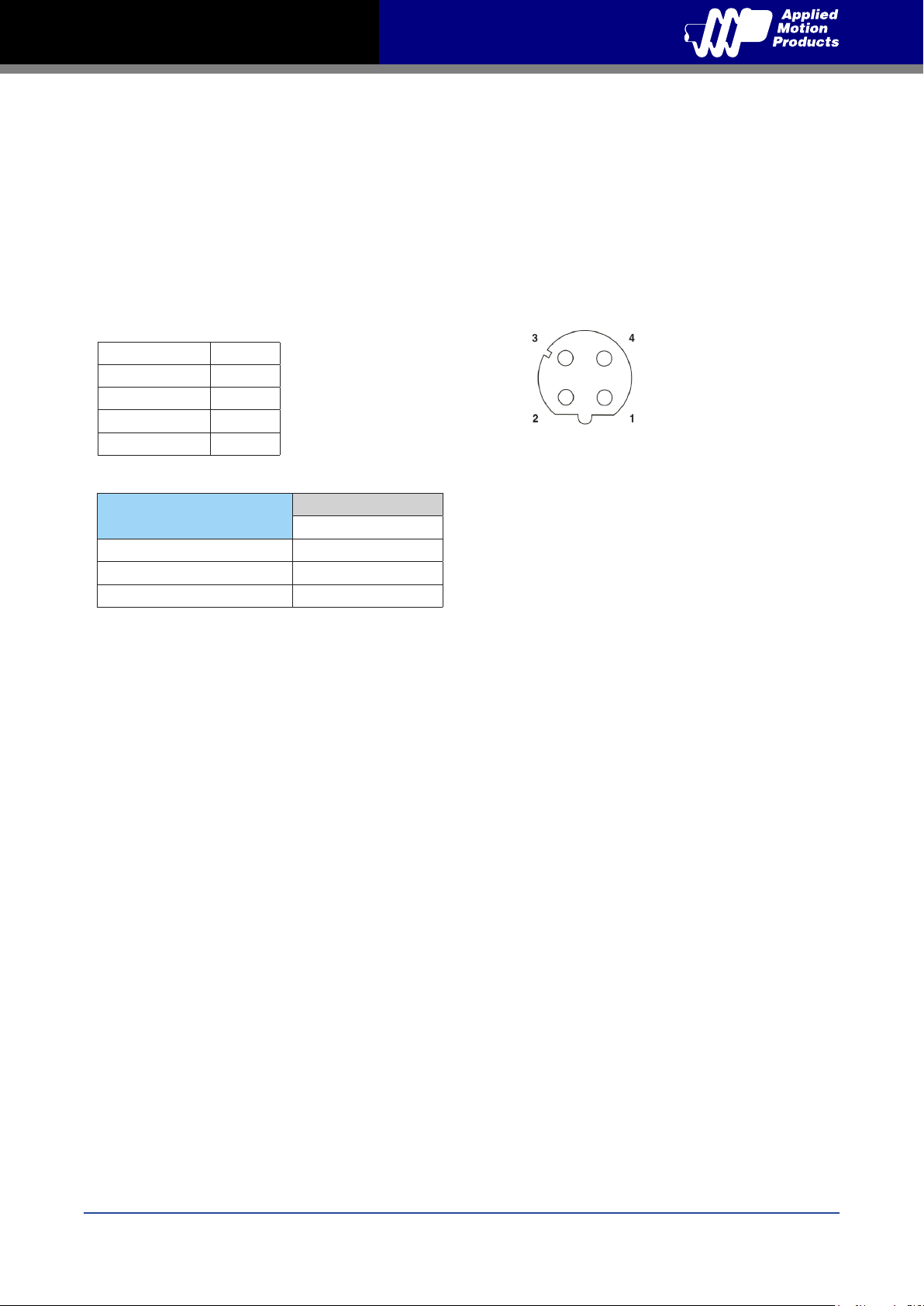
The communications interface for the TXM24 Ethernet is one standard 4-pin M12 connectors. The
TXM24 is congured by Step-Servo Quick Tuner with Ethernet link, and then may be deployed on
a distributed Ethernet network. Below are descriptions of how to interface Ethernet communication
type to a PC.
3.2.1 Connecting to the PC using Ethernet
Communication port
Signal Pin no.
TX+ 1
RX+ 2
TX- 3
RX- 4
View of motor side connector 1551529
Model
TXM24S-3EG, TXM24S-1EG
TXM24Q-3EG, TXM24Q-1EG
TXM24IP-3EG, TXM24IP-3EG
Communications
Ethernet
Rev. C
920-0089
12
Page 13

TXM24 Ethernet Hardware Manual
3.3 Connecting the Drive to Your PC using Ethernet
This process requires three steps:
• Physically connect the drive to your network (or directly to the PC)
• Set the drive’s IP address
• Set the appropriate networking properties on your PC.
3.3.1 Addresses, Subnets, and Ports
Every device on an Ethernet network must have a unique IP address. In order for two devices to
communicate with each other, they must both be connected to the network and they must have
IP addresses that are on the same subnet. A subnet is a logical division of a larger network.
Members of one subnet are generally not able to communicate with members of another unless
they are connected through special network equipment (e.g. router). Subnets are dened by the
choices of IP addresses and subnet masks.
If you want to know the IP address and subnet mask of your PC, select Start…All Programs…
Accessories…Command Prompt. Then type “ipcong” and press Enter. You should see something
like this:
If your PC’s subnet mask is set to 255.255.255.0, a common setting known as a Class C subnet
mask, then your machine can only talk to another network device whose IP address matches
yours in the rst three octets. (The numbers between the dots in an IP address are called octets.)
For example, if your PC is on a Class C subnet and has an IP address of 192.168.0.20, it can talk
to a device at 192.168.0.40, but not one at 192.168.1.40. If you change your subnet mask to
255.255.0.0 (Class B) you can talk to any device whose rst two octets match yours. Be sure to
ask your system administrator before doing this. You network may be segmented for a reason.
Your drive’s IP Address is stored internally in nonvolatile memory. The factory default address is
192.168.1.10. This address can be changed using our Step Servo Quick Tuner software.
If someone were to change the setting and not write it down or tell anyone then you will not be
able to communicate with your drive. The only way to “recover” it is to apply power to the TXM24
with the network cable unplugged. The TXM24 will detect this condition and revert to a recovery
address of 10.10.10.10. You may then connect your cable to the network and use Step Servo
Quick Tuner to upload and change the stored address (using IP Table in the menu). Your PC, or
any other device that you use to communicate with the drive, will also have a unique address.
Use the standard class B subnet mask (i.e. “255.255.0.0”). The mask for the recovery address
is the standard class A (i.e. “255.0.0.0”). One of the great features of Ethernet is the ability for
many applications to share the network at the same time. Ports are used to direct trafc to the
right application once it gets to the right IP address. The UDP eSCL port in our drives is 7775. To
send and receive commands using TCP, use port number 7776. You’ll need to know this when you
begin to write your own application. You will also need to choose an open (unused) port number
13
Rev. C
920-0089
Page 14
TXM24 Ethernet Hardware Manual
for your application. Our drive doesn’t care what that is; when the rst command is sent to the
drive, the drive will make note of the IP address and port number from which it originated and
direct any responses there. The drive will also refuse any trafc from other IP addresses that is
headed for the eSCL port. The rst application to talk to a drive “owns” the drive. This lock is only
reset when the drive powers down.
If you need help choosing a port number for your application, you can nd a list of commonly used
port numbers at http://www.iana.org/assignments/port-numbers.
One nal note: Ethernet communication can use one or both of two “transport protocols”: UDP and
TCP. eSCL commands can be sent and received using either protocol. UDP is simpler and more
efcient than TCP, but TCP is more reliable on large or very busy networks where UDP packets
might occasionally be dropped.
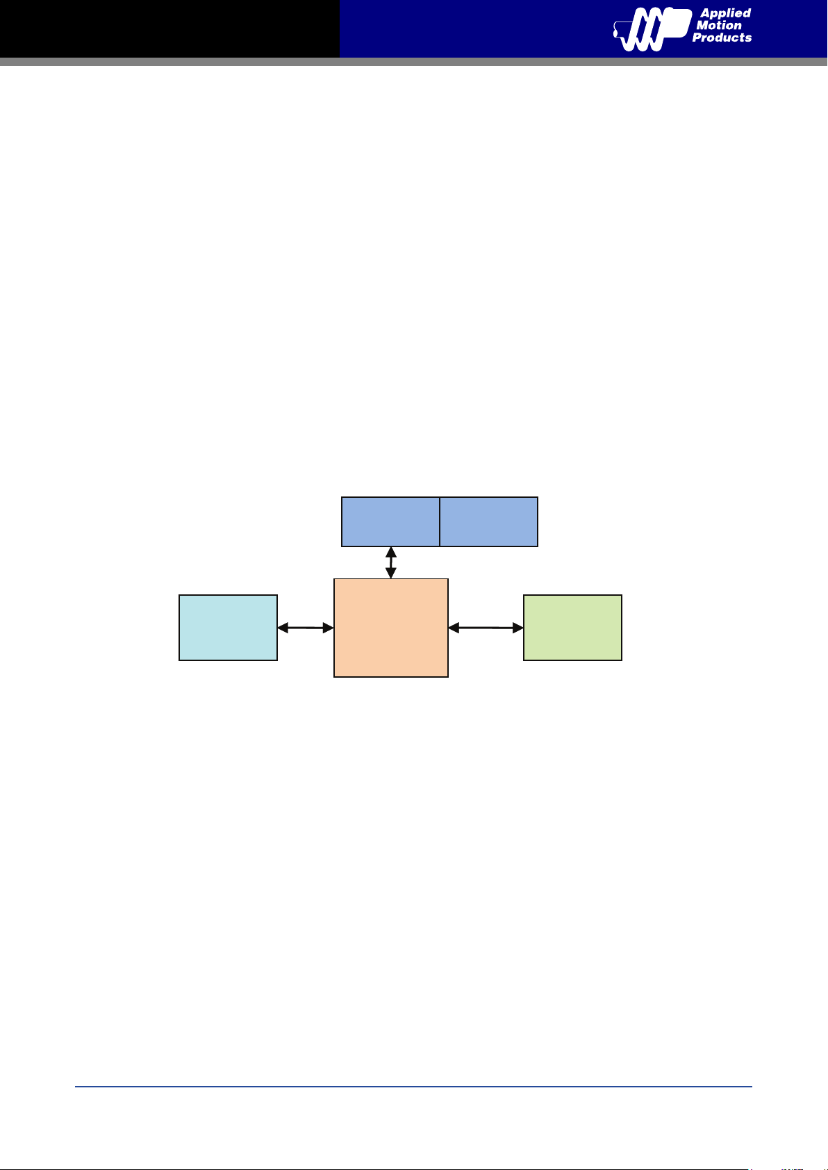
3.3.2 Option 1: Connect a Drive to Your Local Area Network
If you have a spare port on a switch or router and if you are able to set your drive to an IP address
that is compatible with your network, and not used by anything else, this is a simple way to get
connected. This technique also allows you to connect multiple drives to your PC. If you are on a
corporate network, please check with your system administrator before connecting anything new
to the network. He or she should be able assign you a suitable address and help you get going.
PC NIC
SWITCH
LAN DRIVE
or
RETUOR
Once you’ve chosen an appropriate IP address for your drive, set the IP address using Step-Servo
Quick Tuner. If the default address is not acceptable for you network, you can enter a new IP
address using Step-Servo Quick Tuner.
If your PC address is not in 192.168.1. subnet, you will have to change your subnet mask to
255.255.0.0 in order to talk to your drive. To change your subnet mask:
1. On Windows XP, right click on “My Network Places” and select properties. On Windows 7, click
Computer. Scroll down the left pane until you see “Network”. Right click and select properties.
Select “Change adapter settings”
2. You should see an icon for your network interface card (NIC). Right click and select properties.
3. Scroll down until you see “Internet Properties (TCP/IP)”. Select this item and click the Properties
button. On Windows 7 and Vista, look for “(TCP/IPv4)”
4. If the option “Obtain an IP address automatically” is selected, your PC is getting an IP address
and a subnet mask from the DHCP server. Please cancel this dialog .
Rev. C
920-0089
14
Page 15

TXM24 Ethernet Hardware Manual
5. If the option “Use the following IP address” is selected, life is good. Change the subnet mask to
“255.255.0.0” and click OK.
3.3.3 Option 2: Connect a Drive Directly to Your PC
It doesn’t get much simpler than this:
1. Connect one end of a CAT5 Ethernet cable into the LAN card (NIC) on your PC and the other
into the drive. You don’t need a special “crossover cable”; the drive will automatically detect the
direct connection and make the necessary physical layer changes.
2. The factory default IP address of the drive is “192.168.1.10”.
3. To set the IP address of your PC:
a. On Windows XP, right click on “My Network Places” and select properties.
b. On Windows 7, click Computer. Scroll down the left pane until you see “Network”. Right click
and select properties. Select “Change adapter settings”
4. You should see an icon for your network interface card (NIC). Right click and select properties.
a. Scroll down until you see “Internet Properties (TCP/IP)”. Select this item and click the
Properties button.
b. On Windows 7 and Vista, look for “(TCP/IPv4)”
5. Select the option “Use the following IP address”. Then enter the address “192.168.1.11”. This
will give your PC an IP address that is on the same subnet as the drive. Windows will know to
direct any trafc intended for the drive’s IP address to this interface card.
6. Next, enter the subnet mask as “255.255.255.0”.
7. Be sure to leave “Default gateway” blank. This will prevent your PC from looking for a router on
this subnet.
15
Rev. C
920-0089
Page 16
TXM24 Ethernet Hardware Manual
8. Because you are connected directly to the drive, anytime the drive is not powered on your PC
will annoy you with a small message bubble in the corner of your screen saying “The network
cable is unplugged.”
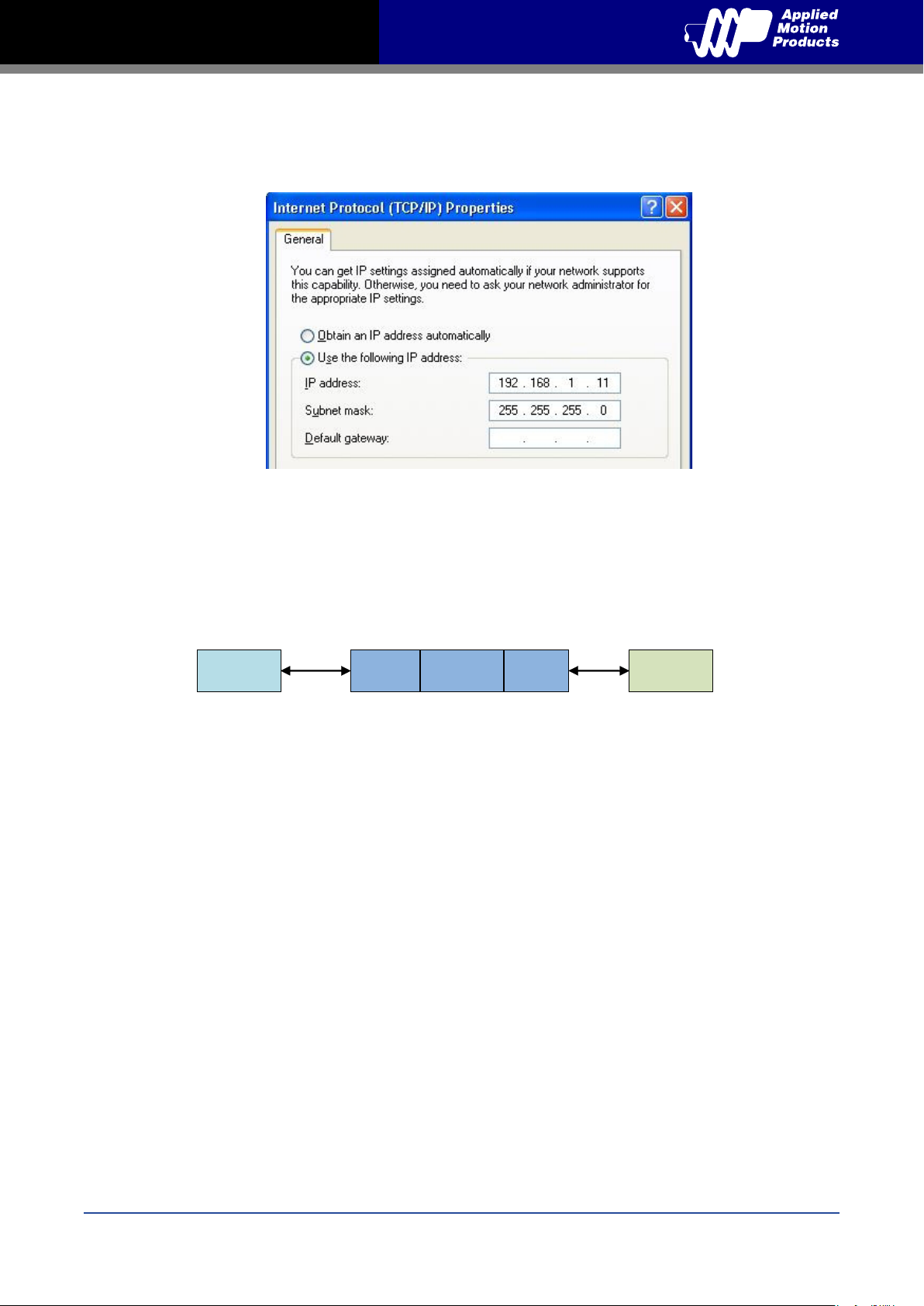
3.3.4 Option 3: Use Two Network Interface Cards (NICs)
This technique allows you to keep your PC connected to your LAN, but keeps the drive off the
LAN, preventing possible IP conicts or excessive trafc.
1. If you use a desktop PC and have a spare card slot, install a second NIC and connect it
directly to the drive using a CAT5 cable. You don’t need a special “crossover cable”; the drive will
automatically detect the direct connection and make the necessary physical layer changes.
PC NIC1 NIC2 LAN DRIVE
2. If you use a laptop and only connect to your LAN using wireless networking, you can use the
built-in RJ45 Ethernet connection as your second NIC.
3. The factory default IP address of the drive is “192.168.1.10”.
4. To set the IP address of the second NIC:
a. On Windows XP, right click on “My Network Places” and select properties.
b. On Windows 7, click Computer. Scroll down the left pane until you see “Network”. Right click
and select properties. Select “Change adapter settings”
5. You should see an icon for your newly instated NIC. Right click again and select properties.
a. Scroll down until you see “Internet Properties (TCP/IP)”. Select this item and click the
Properties button.
b. On Windows 7 and Vista, look for “(TCP/IPv4)”
6. Select the option “Use the following IP address”. Then enter the address “192.168.1.11”. This
will give your PC an IP address that is on the same subnet as the drive. Windows will know to
direct any trafc intended for the drive’s IP address to this interface card.
7. Next, enter the subnet mask as “255.255.255.0”. Be sure to leave “Default gateway” blank. This
will prevent your PC from looking for a router on this subnet.
8. Because you are connected directly to the drive, anytime the drive is not powered on your PC
will annoy you with a small message bubble in the corner of your screen saying “The network
cable is unplugged.”
Rev. C
920-0089
16
Page 17
TXM24 Ethernet Hardware Manual
3.4 Inputs and Outputs
The TXM24 has three types of inputs:
• High speed digital inputs for step & direction commands or encoder following, 5 to 24 volt logic
• Low speed digital input for other signals, 5 to 24 volt logic
• Analog input for analog speed and positioning modes
All drives include 3 digital inputs and 1 analog input
• STEP & DIR are high-speed digital inputs for commanding position. Quadrature signals from
encoders can also be used. When not being used for the Step & Direction function these
inputs can be used for CW & CCW Limit, CW & CCW Jogging and Run/Stop & Direction
Velocity modes.
• EN is a low speed software programmable input and can be used for Motor Enable and/or
Alarm Reset. This input can also be connected to a sensor, switch or other device for use with
Wait Input (WI), Seek Home (SH), Feed to Sensor (FS), On Input (OI) and other commands.
• AIN is an analog input for a velocity or position command signal. It can accept 0-5 volts and
has gain, ltering, offset and dead-band settings.
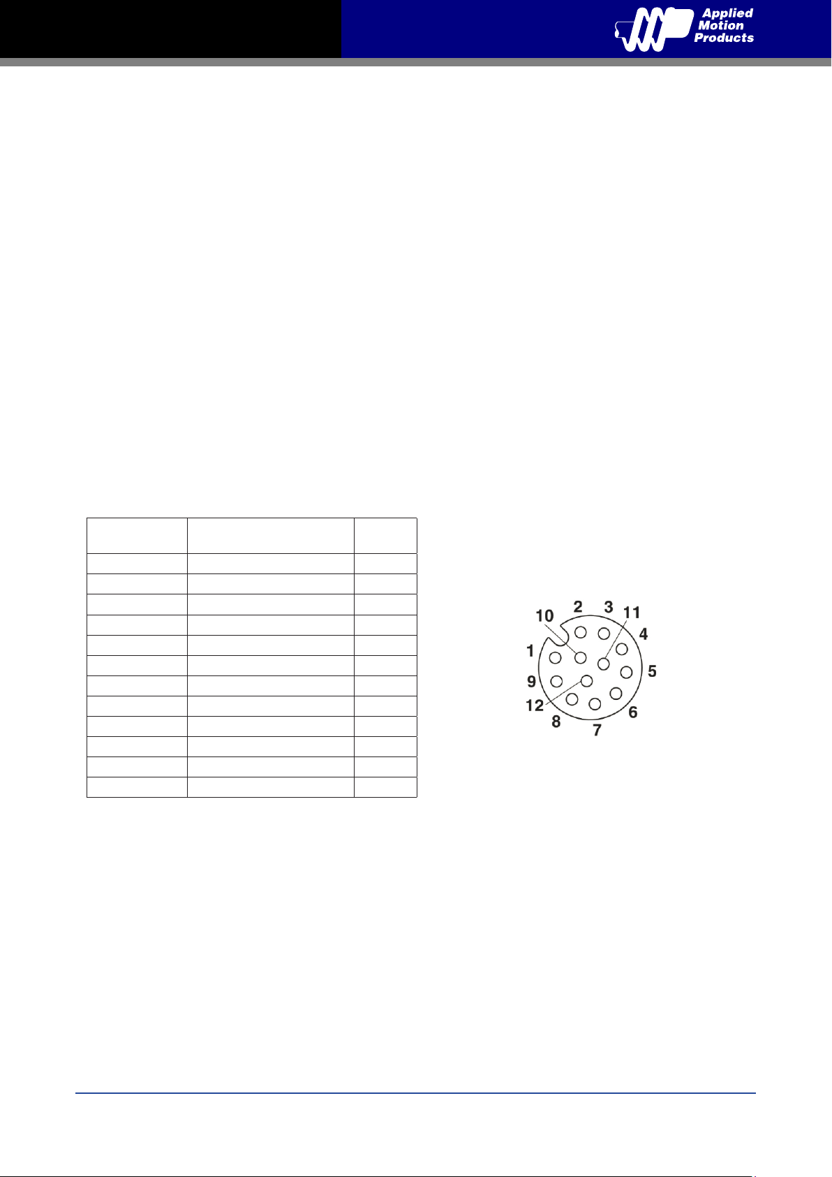
3.4.1 Connector Pin Diagram
IO
Signal
Step+ BN 1
Step- WH 3
Dir+ PK 5
Dir- GY 8
En+ YE 6
En- GN 4
OUT+ GYPK 11
OUT- RDBU 12
+5V RD 9
AIN VT 10
GND BK 7
N/C BU 2
Color of mating cable
Phoenix P/N 1554775
Pin no.
View of motor side connector
17
Rev. C
920-0089
Page 18
TXM24 Ethernet Hardware Manual
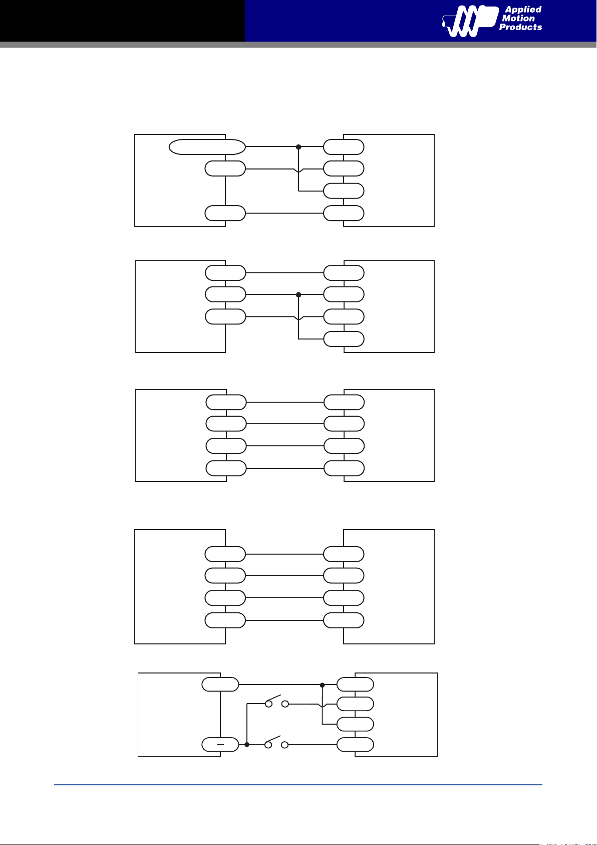
3.4.2 STEP & DIR Digital Inputs
The diagrams below show how to connect the STEP & DIR Inputs to various commonly used
devices.
+5v to +24v out
Indexer
DIR
DIR+
DIR-
with
Sinking
Outputs
STEP
STEP+
STEP-
Connecting to Indexer with Sinking Outputs
DIR
DIR+
Indexer
with
Sourcing
COM
STEP
DIR-
STEP+
Outputs
STEP-
Connecting to Indexer with Sourcing Outputs
DIR+
DIR+
Indexer
with
Differential
DIR-
STEP+
DIR-
STEP+
Outputs
STEP-
STEP-
TXM24
TXM24
TXM24
Connecting to Indexer with Differential Outputs
Many high-speed indexers have differential outputs
Master
Encoder
A+
A-
B+
B-
STEP+
STEP-
DIR+
DIR-
Wiring for Encoder Following
5 - 24
volt DC
Power
Supply
+
direction switch
run/stop switch
(closed = run)
Using Mechanical Switches
DIR+
DIR-
STEP+
STEP-
TXM24
TXM24
Rev. C
920-0089
18
Page 19
TXM24 Ethernet Hardware Manual
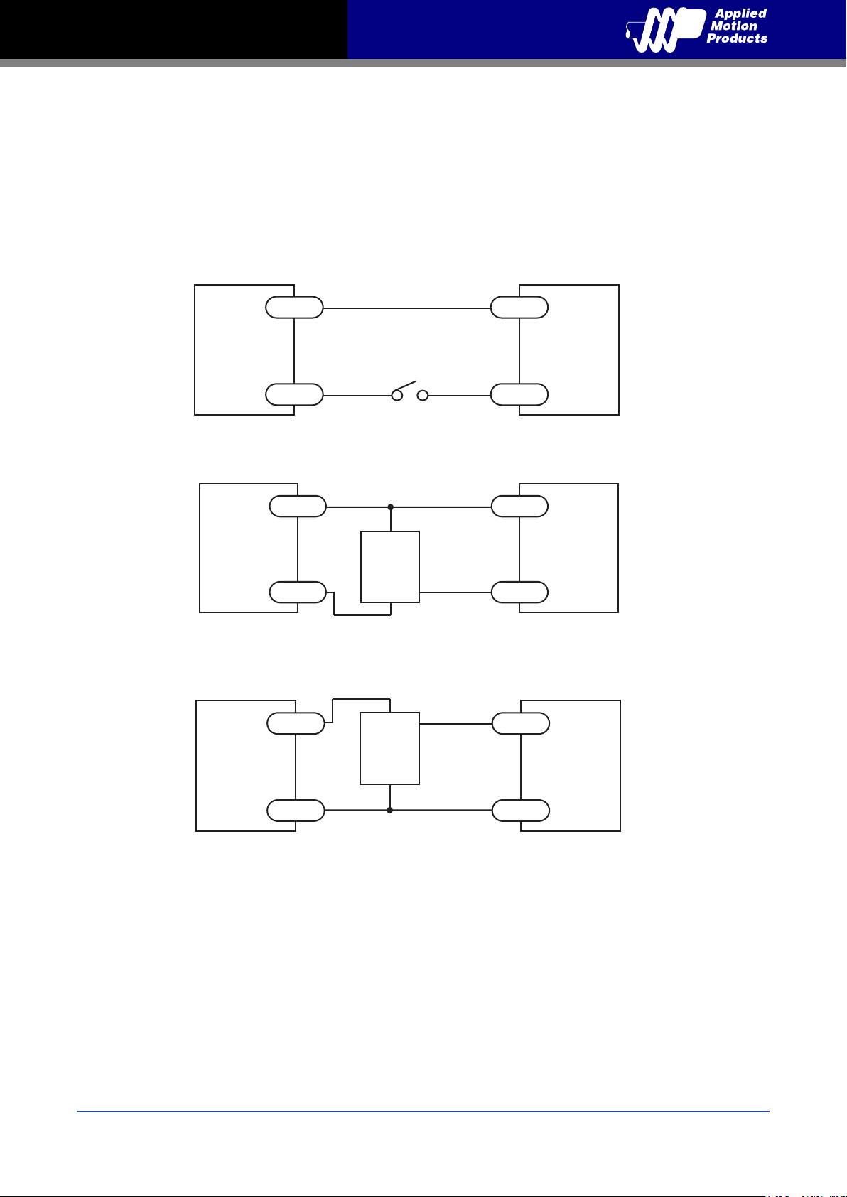
(when prox sensor activates, input goes high)
3.4.3 EN Digital Input
While the STEP and DIR inputs are designed for high-speed digital input operation, the Enable
(EN) input is designed for low speed digital input operation between 5 and 24 volts.
Note: If current is owing into or out of an input, the logic state of that input is low or closed. If no
current is owing, or the input is not connected, the logic state is high or open.
The diagrams below show how to connect the EN input to various commonly used devices.
5 - 24
volt DC
Power
+
Switch or Relay
(closed = logic low)
EN+
TXM24
Supply
-
EN-
Connecting the Input to a Switch or Relay
5 - 24
volt DC
Power
Supply
+
-
+
NPN
Proximity
Sensor
-
output
EN+
TXM24
EN-
Connecting an NPN type Proximity Sensor to an Input
(when prox sensor activates, input goes low)
output
EN+
TXM24
5 - 24
volt DC
Power
+
+
PNP
Proximity
Sensor
-
Supply
-
EN-
Connecting a PNP type Proximity Sensor to an Input
19
Rev. C
920-0089
Page 20
TXM24 Ethernet Hardware Manual
3.4.4 AIN Input
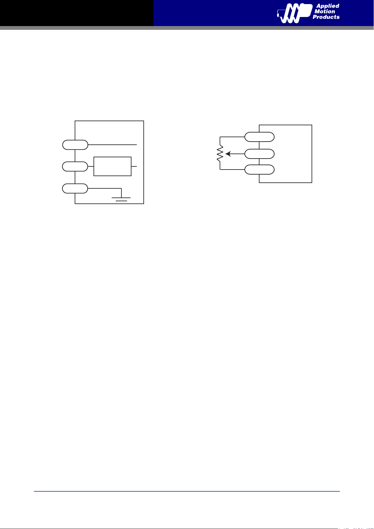
The TXM24 drives have an analog input (AIN) which can accept a signal range of 0 to 5 volts. The
drive can be congured to operate at a speed or position that is proportional to the analog signal.
Use the Step-Servo Quick Tuner software to set the signal range, offset, dead-band and lter
frequency. The TXM24 provides a +5 volt 100mA limit voltage supply that can be used to power
external devices such as potentiometers. It is not the most accurate supply for reference, for more
precise readings use an external supply that can provide the desired accuracy.
inside drive
rotcennoC O/I
+5v
AIN
100 mA limit
Signal
Conditioning
1 - 10k
pot
Ω
+5v OUT
AIN
GND
TXM24
GND
Connecting a Potentiometer
to the Analog Input
Rev. C
920-0089
20
Page 21
TXM24 Ethernet Hardware Manual
3.4.5 Programmable Output
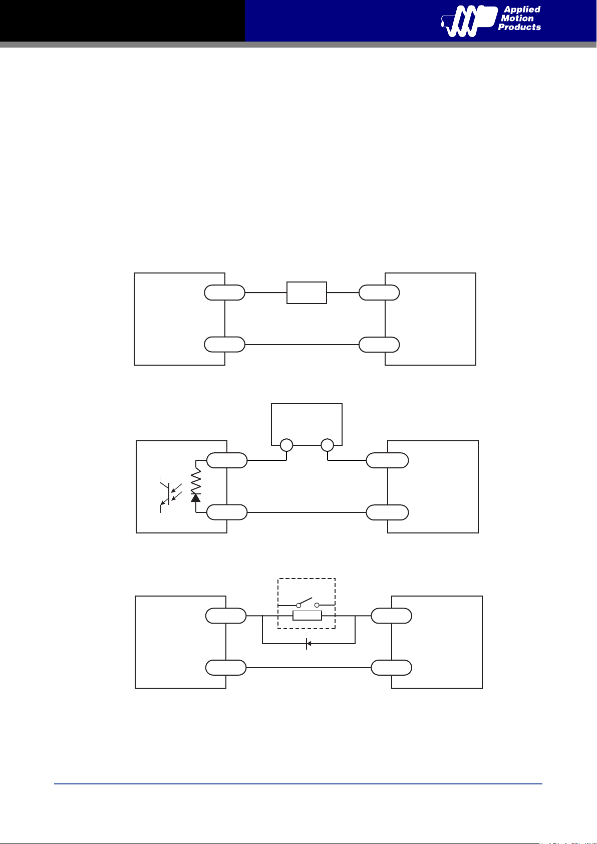
The TXM24 drives feature one optically isolated digital output (OUT). This output can be set to
automatically control a motor brake, to signal a fault condition, to indicate when the motor is in
position or to provide an output frequency proportional to motor speed (tach signal). Or the output
can be turned on and off by program instructions like Set Output (SO). The output can be used to
drive LEDs, relays and the inputs of other electronic devices like PLCs and counters. The OUT+
(collector) and OUT- (emitter) terminals of the transistor are available at the connector. This allows
the output to be congured for current sourcing or sinking.
Diagrams of various connection types follow.
Do not connect the output to more than 30 volts. The current through the output terminal
must not exceed 100mA.
5 - 24
volt DC
Power
Supply
PLC
+
Load
-
Connecting a Sinking Output
5 - 24VDC
Power Supply
-
COM
IN
Connecting a Sourcing Output
+
OUT+
TXM24
OUT-
OUT+
TXM24
OUT-
5 - 24
volt DC
Power
Supply
+
-
relay
1N4935 suppresion diode
Driving a Relay
21
OUT+
TXM24
OUT-
Rev. C
920-0089
Page 22
TXM24 Ethernet Hardware Manual
4 Troubleshooting
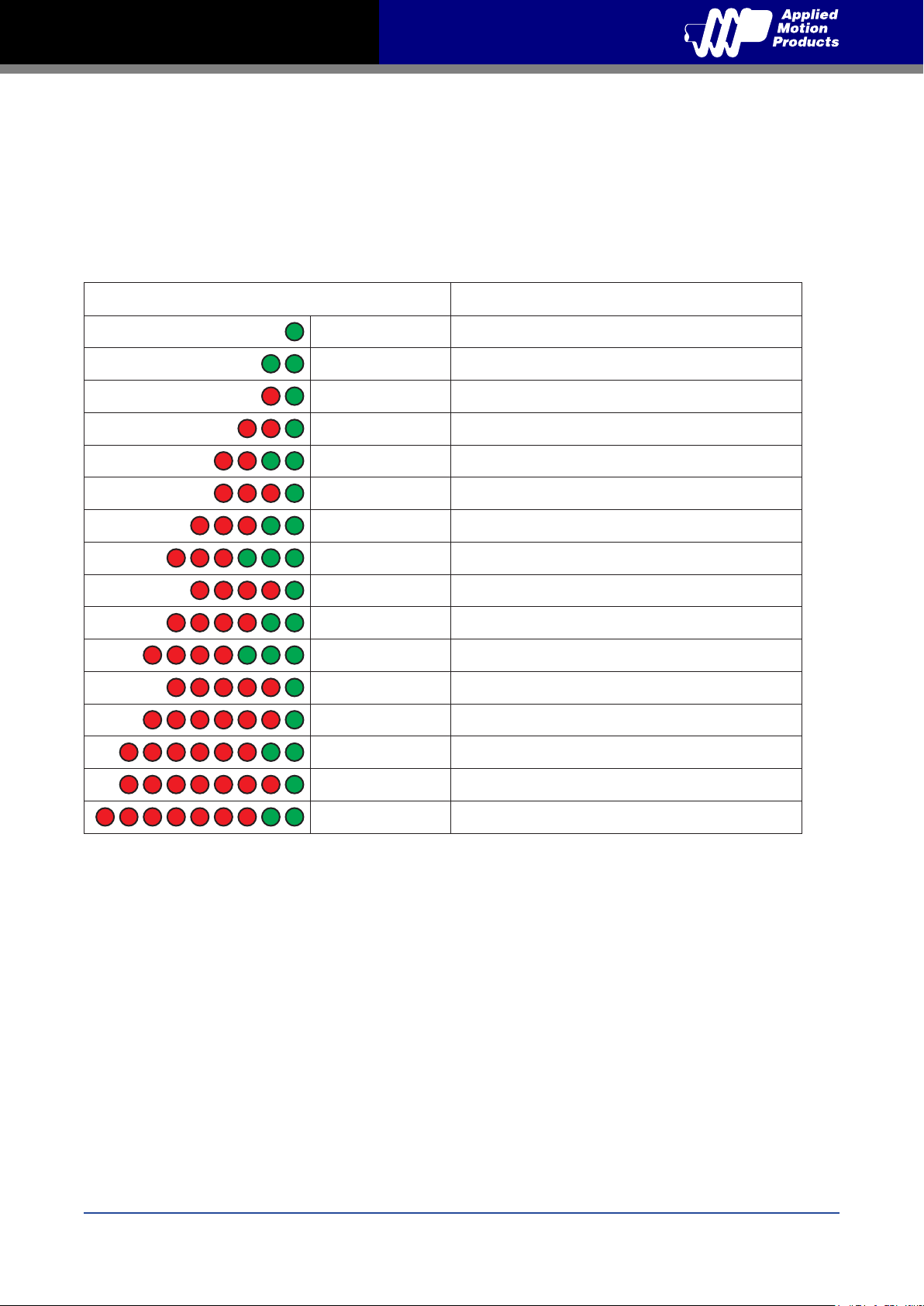
LED Error Codes
The TXM24 uses bi-colour LED to indicate status. When the motor is enabled, the green LED
ashes slowly. When the green LED is solid, the motor is disabled. Errors are indicated by
combinations of red and green ashes as shown below. This feature can be disabled for certain
warnings but not for alarms.
Code Error
Solid green No alarm,motor disabled
Flashing green No alarm,motor enabled
1 red,1 green
2 red,1 green
2 red,2 green
Motor stall (optional encoder only)
CCW limit
CW limit
3 red,1 green Drive overheating
3 red,2 green Internal voltage out of range
3 red,3 green
Blank Q segment
4 red,1 green Power supply overvoltage or excess regen
4 red,2 green Power supply undervoltage
4 red,3 green
Flash memory backup error
5 red,1 green Over current/short circuit
6 red,1 green Open motor winding
6 red,2 green
Bad encoder signal (optional encoder only)
Rev. C
920-0089
7 red,1 green
7 red,2 green
Communication error
Flash memory error
22
Page 23
TXM24 Ethernet Hardware Manual
5 Reference Materials
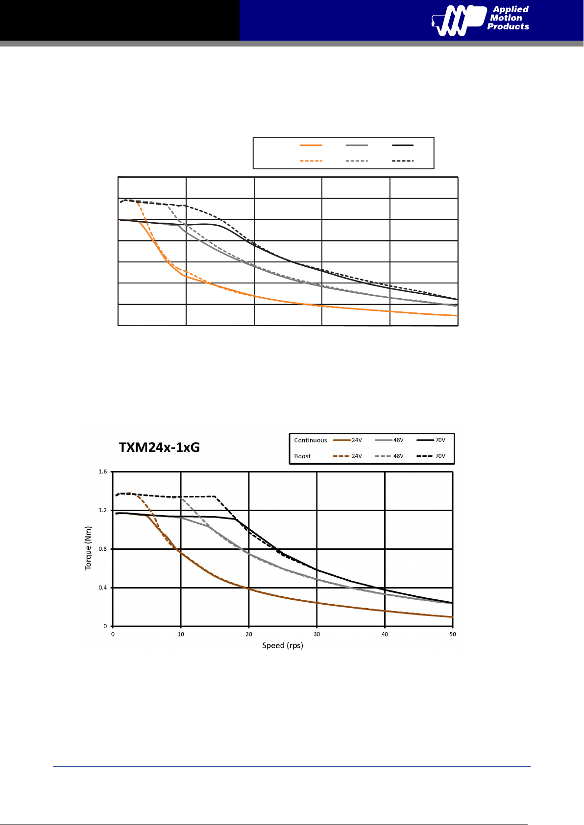
5.1 Torque-Speed Curves
TXM24□-3□G
3.5
3
2.5
2
1.5
Torque(N·m)
1
0.5
0
0 10 20 30 40 50
Continuous
Boost
Speed(rps)
24V 48V 70V
24V 48V 70V
Note: all torque curves were measured at 20,000 steps/rev.
Note: 6 amp rating is continuous, 7.5 amp rating is boost
23
Rev. C
920-0089
Page 24
TXM24 Ethernet Hardware Manual
Unit:mm
1.5
20 Flat
24
8
130.8
111
60
9.5 Flat
Ø10
60
47.14
47.14
4-Ø4.5
Ø38.1
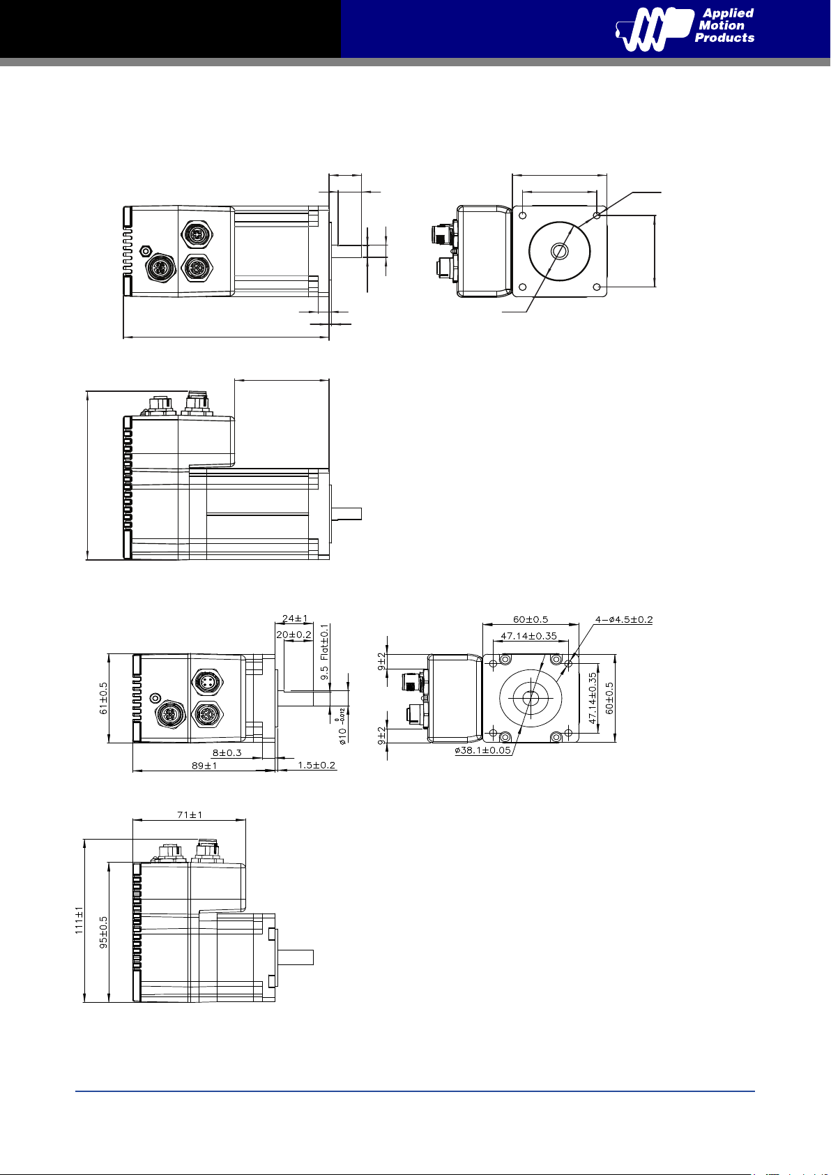
5.2 Mechanical Outlines
TXM24S/Q/IP-3EG
TXM24S/Q/IP-1EG
Rev. C
920-0089
24
Page 25
TXM24 Ethernet Hardware Manual
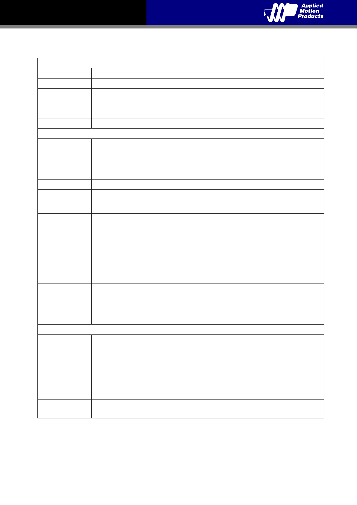
5.3 Technical Specications
Amplier Type Dual H-Bridge, 4 Quadrant
Current Control 4 state PWM at 20 KHz
Power Amplier
Output Torque
TXM24S/Q/IP-3EG: Up to 2.4N•m Continuous (3.0 N•m Boost)
TXM24S/Q/IP-1EG: Up to 0.82N•m Continuous (1.03 N•m Boost)
Power Supply External 12 - 70 VDC power supply required
Protection Over-voltage, under-voltage, over-temp, motor/wiring shorts (phase-to-phase, phase-to-ground)
Controller
Electronic Gearing Software selectable from 200 to 51200 steps/rev in increments of 2 steps/rev
Encoder Resolution 20000 counts/rev
Speed Range Up to 3600rpm
Filters Digital input noise lter, Analog input noise lter, Smoothing lter, PID lter, Notch lter
Non-Volatile Storage
Congurations are saved in FLASH memory on-board the DSP
TXM24S: Step & direction, CW/CCW pulse, A/B quadrature pulse, velocity (oscillator, joystick),
Modes of Operation
streaming commands(SCL)
TXM24Q/IP: All TXM24S modes of operation plus stored Q program execution
Digital Inputs Adjustable bandwidth digital noise rejection lter on all inputs
STEP+/- : Optically isolated, 5-24 volt. Minimum pulse width = 250 ns, Maximum pulse frequency = 2 MHz
Function: Step, CW step, A quadrature (encoder following), CW limit, CW jog, start/stop (oscillator
mode), or general purpose input
Digital Inputs
DIR+/- : Optically isolated, 5-24 volt. Minimum pulse width = 250 ns, Maximum pulse frequency = 2 MHz
Function: Direction, CCW step, B quadrature (encoder following), CCW limit, CCW jog, direction
(oscillator mode), or general purpose input
EN+/- : Optically isolated, 5-24 volt. Minimum pulse width = 100 μs, Maximum pulse frequeny = 10 KHz
Function: Enable, alarm/fault reset, speed 1/speed 2 (oscillator mode), or general purpose input
Digital Output
OUT+/-: Optically isolated, 30V/100 mA max.
Function: Fault, tach, in position, brake, or general purpose programmable
Analog Input AIN referenced to GND. Range = 0 to 5 VDC. Resolution = 12 bits
Communication
Interface
Ethernet UDP/TCP, EtherNet/IP
Physical
Ambient
Temperature
0 to 40°C (32 to 104°F) When mounted to a suitable heatsink
Humdity 90% Max., non-condensing
Mass
Rotor Inertia
Length
TXM24S/Q/IP-3EG: 2000 g = 70.55 oz
TXM24S/Q/IP-1EG: 1049 g = 37 oz
TXM24S/Q/IP-3EG: 900 g•cm
TXM24S/Q/IP-1EG: 260 g•cm
2
= 1.27 X 10⁻² oz-in-S
2
= 3.97E-03 oz-in-S
TXM24S/Q/IP-3EG 5.15 inches (130.8mm)
TXM24S/Q/IP-1EG 3.5 inches (88.9mm)
2
2
25
Rev. C
920-0089
Page 26

TXM24 Ethernet Hardware Manual
5.4 Accessories
Mating Cables
Position Part Number Description
Power 3004-277-5M 4-pin Mating Cable, M12, 2.0m, 22AWG, straight
I/O 3004-290-5M 12-pin Mating Cable, M12,1.5m, 26AWG, straight
Ethernet 3004-280-5M
Bus system connector, plug, straight, 4-pos., M12 shielded,
D-coded
6 Contacting Applied Motion Products
404 Westridge Dr.
Watsonville, CA 95076, USA
1-800-525-1609
Tel (831) 761-6555
Fax (831) 761-6544
www.applied-motion.com
Rev. C
920-0089
26
 Loading...