


|
330062-1 |
|||
|
|
|
INSTRUCTION SHEET |
|
|
|
|
|
|
Class I, Div. 1 and 2 |
U-LINE®, CONTENDER® U-LINE®, EFS/EFSR/ENR SERIES |
|||
Groups B◊, C, D |
INSTALLATION AND MAINTENANCE INSTRUCTION |
|||
Class II, Div. 1 and 2 |
|
|
|
|
Groups F, G |
|
|
|
|
Class III |
|
|
|
|
Type: 3RX |
|
|
|
|
|
|
|
|
|
|
|
|
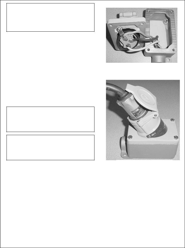
Figure 1A |
|
|
|
|
|
|
APPLICATION and FEATURES:
•U-Line®/Contender® U-Line® receptacles and ECP/NCP plugs combination are designed for use where power is to be supplied to portable electric equipment in locations which are hazardous due to the presence of flammable vapors and gases or locations where damp or corrosive conditions are encountered.
•These plugs and receptacles are for 15 or 20 ampere use at 125 volts AC and 20 ampere use at 250 volts AC.
•U-Line® receptacles mount on single or double-gang EFD series boxes. Contender® U-Line® receptacles mount on single or double-gang EDS series boxes.
•Receptacle is grounded through and extra pole as well as through the receptacle housing.
INSTALLATION:
ELECTRICAL WARNING
Electrical power supply must be “OFF” before and during installation and maintenance. Failure to do so may result in serious or fatal injuries due to electrocution.
Note: Use minimum #12 copper or copper clad building wire
1.Mount receptacle back box in desired location. If receptacle is already mounted on the box, take out four mounting screws and remove receptacle. Pull in power source wiring to the box, making sure wire leads extend out of box far enough for proper connections to be made (See Figure 2).
2.Strip insulation from power lead ½”. Connect power leads to receptacle terminals. Wiring must comply with applicable local codes (See Figure 3).
3.To make connections, loosen wire screws, slide stripped end of wire into contact and tighten wire screw to 20 in-lb torque (See Figure 4).
4.Apply a thin film of lubricant (supplied with receptacle) to the flange. Reinstall receptacle on the flange and tighten four mounting screws provided to 30 in-lb torque. Receptacle assembly is now complete and power may now be turned on.
Retain this instruction sheet for future reference.
For Convenience…ECP InterchangerTM Plug fits ordinary location receptacles (NEMA 5-20 or 15 NEMA 620) and explosion proof U-Line® Receptacle as well as Killark® “UGR” Series and Crouse-Hinds® “ENR” Series.
Figure 1B
Figure 2 |
|
Figure 3 |
|
|
|
|
|
|
|
Grounded White Lead |
|
Black Lead |
||
connection for 125V, Black |
Connection |
|||
Lead connection for 250V |
|
|
||
Note: For 250V, there are 2 blacks wires, connect one to black lead and other to indicated white lead as shown.
Rev. A 02/18/09 Page 1
CAUTION
The mating flat flange surfaces on both receptacle and back box are explosion-proof surfaces. Surfaces are not to be scratched and MUST be clean and flat before assembly. Gaskets, paint, or any other similar material must NOT be used in this joint.
OPERATION:
The U-Line®/Contender U-Line® receptacle is dead-front construction. Electrical connection between it and ECP/NCP plug is accomplished after plug fully inserts into receptacle and rotate clockwise.
1. Lift receptacle door and locate polarization on mating plug pin and receptacle face. Insert plug straight all the way into receptacle until it can not go further (see figure 5).
2. Rotate plug clockwise limit (37º), this closes internal contacts and completes circuit. This also mechanically locks plug into receptacle so it cannot be pulled out.
3. To remove plug, push plug inward and turn to counterclockwise, pull plug straight out.
MAINTAENANCE:
Electrical and mechanical inspection of all components must be performed on a regularly scheduled basic, determined by the environment and frequency of use. It is recommended that inspection be performed a minimum of once a year.
WARNING
Electrical power supply must be “OFF” before and during installation and maintenance. Installation and maintenance procedure must be performed by a trained and competent electrician.
WARNING
If any parts of the receptacle or plug appear to be missing, broken, or show signs or damage, DISCONTINUE USE IMMEDIATELY. Replace with the proper replacement part(s) before continuing service.
1.Inspect all contact wire terminals for tightness. Discoloration due to excessive heat is an indicator of a possible problem and should be thoroughly investigated and repaired as necessary.
2.Inspect contacts for signs of wear and replace if necessary.
3.Clean exterior surfaces making sure nameplates remain legible.
4.Check tightness of all screws before using.
Figure 4 (mounting receptacle onto back box with hinge in UP position)
Figure 5 - Plug Inserts In Receptacle
|
Replacement Parts |
|
|
|
Catalog No. |
Description |
|
|
|
|
|
|
|
|
125 V |
250 V |
|
|
|
|
|
|
|
|
EFSR-2023 |
EFSR-20232 |
Receptacle cover (aluminum). |
|
|
EFSR-2023K |
EFSR-20232K |
Receptacle for use on Killark SWB boxes |
|
|
|
|
|||
EFSR-2023M |
EFSR-20232M |
Receptacle cover (malleable iron) |
|
Figure 6 |
ENR5201 |
ENR6202 |
Contenter® receptacle cover (aluminum) |
|
Receptacle |
ULINE3RXKIT |
ULINE3RXKIT |
Screw cover kit |
|
Cover |
ULSCM |
ULSCM |
Flip cover & ring kit, malleable iron. |
|
|
|
|
|||
ULSCA |
ULSCA |
Flip cover & ring kit, aluminum. |
|
|
59308097000 |
59308097000 |
Receptacle gasket |
|
|
|
|
|
|
|
Page 2 330032-1 Rev. A 02/18/09
 Loading...