

Page 1
INSTRUCTION SHEET
U-LINE®, CONTENDER® U-LINE®, EFS/EFSR/ENR SERIES
Class I, Div. 1 and 2
Groups B◊, C, D
INSTALLATION AND MAINTENANCE INSTRUCTION
Class II, Div. 1 and 2
Groups F, G
Class III
Type: 3RX
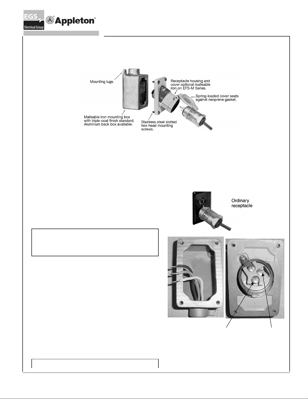
Figure 1A
APPLICATION and FEATURES:
•U-Line®/Contender® U-Line® receptacles and ECP/NC
ugs combination are designed for use where power is to be
pl
supplied to portable electric equipment in locations which
hazardous
lo
cations where damp or corrosive conditions are encountered.
• These
vol
•U-Line® receptacles mount on single or double-gang EF
series boxes. Contender® U-Line® receptacles mount on single
or double-gang EDS series boxes.
• Receptacle is grounde
through the receptacle housing.
INSTALLATION:
due to the presence of flammable vapors and gas
plugs and receptacles are for 15 or 20 ampere use at
ts AC and 20 ampere use at 250 volts AC.
d through and extra pole as well as
P
are
es or
125
D
For Convenience…ECP InterchangerTM Plug fits
ordinary location receptacles (NEMA 5-20 or 15
NEMA 620) and explosion proof U-Line®
Receptacle as well as Killark® “UGR” Series and
Crouse-Hinds® “ENR” Series.
330062-1
Figure 1B
ELECTRICAL WARNING
Electrical power supply must be “OFF” before and during
installation and maintenance. Failure to do so may result
in serious or fatal injuries due to electrocution.
Note: Use minimum #12 copper or copper clad building wire
receptacle back box in desired location. If recept
Mount
1.
al
ready mounted on the box, take out four mounting screws an
rem
ove receptacle. Pull in power source wiring to the box
m
aking sure wire leads extend out of box far enough for prope
con
nections to be made (See Figure 2).
2.Strip insulation from power lead ½”. Connect power leads to
receptacle terminals. Wiring must comply with applicab
codes (See Figure 3).
3. To make connections, loosen wire screws, slide stripped end
wire into contact and tighten wire screw to 20 in-lb torque
of
gure 4).
Fi
4.
Apply a thi
flange.
mounting screws provided to 30 in-lb torque. Receptacle
assembly is now complete and power may now be turned on.
Retain this instruction sheet for future reference.
n film of lubricant (supplied with receptacle) to
Reinstall receptacle on the flange and tighten four
acle is
d
,
r
le local
(See
the
Figure 2
Grounded White Lead
connection for 125V, Black
Lead connection for 250V
Note: For 250V, there are 2 blacks wires, connect
one to black lead and other to indicated white lead
as shown.
Figure 3
Black Lead
Connection
Rev. A 02/18/09 Page 1
Page 2
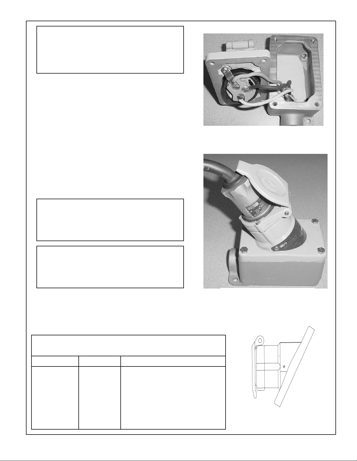
CAUTION
The mating flat flange surfaces on both receptacle and
back box are explosion-proof surfaces. Surfaces are not to
be scratched and MUST be clean and flat before assembly.
Gaskets, paint, or any other similar material must NOT be
used in this joint.
OPERATION:
The U-Line®/Contender U-Line® receptacle is dead-front
construction. Electrical connection between it and ECP/NCP plug
is accomplished after plug fully inserts into receptacle and rotate
clockwise.
receptacle door and locate polarization on mating plug pi
Lift
1.
receptacle face. Insert plug straight all the way into rece
and
u
ntil it can not go further (see figure
2. R
otate plug clockwise limit (37º), this closes internal cont
d completes circuit. This also mechanically locks plug into
an
5).
n
ptacle
acts
receptacle so it cannot be pulled out.
3. To remove plug, push plug inward and turn to counterc
l plug straight out.
pul
lockwise,
MAINTAENANCE:
Electrical and mechanical inspection of all components must
formed on a regularly scheduled basic, determined by th
per
ronment and frequency of use. It is recommended that
envi
be
e
inspection be performed a minimum of once a year.
Figure 4 (mounting receptacle onto back box with
hinge in UP position)
WARNING
Electrical power supply must be “OFF” before and during
installation and maintenance. Installation and
maintenance procedure must be performed by a trained
and competent electrician.
WARNING
If any parts of the receptacle or plug appear to be missing,
broken, or show signs or damage, DISCONTINUE USE
IMMEDIATELY. Replace with the proper replacement
part(s) before continuing service.
1.Inspect all contact wire terminals for tightness. Discolorati
ue to excessive heat is an indicator of a possible problem an
d
sho
uld be thoroughly investigated and repaired as necessary
2. Ins
pect contacts for signs of wear and replace if necessa
lean exterior surfaces making sure nameplates remain legible.
3. C
ry.
4.Check tightness of all screws before using.
Replacement Parts
Catalog No. Description
125 V 250 V
on
Figure 5 - Plug Inserts In Receptacle
d
.
EFSR-2023
EFSR-2023K
EFSR-2023M
ENR5201
EFSR-20232 Receptacle cover (aluminum).
EFSR-20232K Receptacle for use on Killark SWB boxes
EFSR-20232M Receptacle cover (malleable iron)
ENR6202 Contenter® receptacle cover (aluminum)
ULINE3RXKIT ULINE3RXKIT Screw cover kit
ULSCM ULSCM Flip cover & ring kit, malleable iron.
ULSCA ULSCA Flip cover & ring kit, aluminum.
59308097000 59308097000 Receptacle gasket
Page 2 330032-1 Rev. A 02/18/09
Figure 6
Receptacle
Cover
Page 3

Dimensions: U-Line® EFS Receptacle and ECP/NCP Plugs
Single Gang Box Double Gang Box
ECP/NCP Plugs
U-Line® EFS Receptacle Catalog Number
Aluminum Receptacle and Malleable Iron Mounting Box ◊ Malleable Iron Receptacle and Mounting Box
Class I, Groups C & D, Class II, Group F, G, Class III Class I, Groups C & D, Class II, Groups F, G Class III
Suitable for Group B when external seals are used. Suitable for Group B provided external seals are used.
Single Gang-Factory Seal
Type Hub Size 125V 250V 125V 250V
Dead-End ½ EFS150-2023 EFS150-20232 EFS150-2023M EFS150-20232M
¾ EFS175-2023 EFS175-20232 EFS175-2023M EFS175-20232M
1 EFS110-2023 EFS110-20232 EFS110-2023M EFS110-20232M
-2023
Feed-Thru ½ EFSC150-2023 EFSC150-20232 EFSC150-2023M EFSC150
2M
¾ EFSC175-2023 EFSC175-20232 EFSC175-2023M EFSC175-20232M
1 EFSC110-2023 EFSC110-20232 EFSC110-2023M EFSC110-20232M
Two Gang-Factory Seal
Class I, Group C and D, Class II, Group F, G, Class III Class I, Group C and D, Class II, Group F, G, Class III
Dead-End ½ EFS250-2023 EFS250-20232 EFS250-2023M EFS250-20232M
¾ EFS275-2023 EFS275-20232 EFS275-2023M EFS275-20232M
1 EFS210-2023 EFS210-20232 EFS210-2023M EFS210-20232M
Feed-Thru ½ EFSC250-2023 EFSC250-20232 EFSC250-2023M EFSC250-20232M
¾ EFSC275-2023 EFSC275-20232 EFSC275-2023M EFSC275-20232M
1 EF
SC210-2023 EFSC210-20232 EFSC210-2023M EFSC210-20232M
Malleable Iron Receptacle and Mounting Box With Factory Sealed Chamber
Class I, Groups B, C & D, Class II, Groups F, G Class III
No external seals required.
Single Gang-Factory Seal
Type Hub Size 125V 250V
Dead-End ½ EFSB150-2023M EFSB150-20232M
¾ EFSB175-2023M EFSB175-20232M
Feed-Thru ½ EFSCB150-2023M EFSCB150-20232M
¾ EFSCB175-2023M EFSCB175-20232M
Rating Notes:
1. ◊ Single gang aluminum EFSR receptacle cover and malleable iron EFD box suitable for Class I, Div. 1, Group B when
external seals are used (seals must be placed adjacent to each conduit entrance).
2. Single gang malleable iron EFSR receptacle and mounting EFD box suitable for Group B, no external seals
w
hen using with sealing chamber.
required
3. TYPE 3RX when the screw cover is installed and the cover is fully engaged. Apply lubricant provided in the bag on the
cover and all flanges to keep water out.
Ordering Notes:
For Ex: Cat# EFS150-2023A).
For aluminum box and receptacle cover, add suff
Page 3 330062-1 Rev. A 02/18/09
ix A (
Page 4

Dimensions: Contender® U-Line® ENR Receptacle
UNILET
TYPE
1-GANG 1 6.17(15.7) 7.03(17.9) 1(2.5) 2-GANG 1 6.17(15.7) 7.03(17.9) 1(2.5)
HUB SIZE
(IN)
3/4 6.06(15.4) 6.81(17.3) 0.88(2.2) 1/2 & 3/4 6.06(15.4) 6.81(17.3) 0.88(2.2)
1/2 6.06(15.4) 6.81(17.3) 0.75(1.9)
A
"(cm) B"(cm) C"(cm)
UNILET
TYPE
HUB SIZE
(IN)
A
"(cm) B"(cm) C"(cm)
Contender® U-Line® ENR Receptacle Catalog Number
Aluminum Receptacle and Malleable Iron Contender Series Mounting Box
Class I, Groups C & D, Class II, Group F, G, Class III
Single Gang-Factory Seal
Dead-End ½ ENR11201 ENR11202
¾ ENR21201 ENR21202
1 ENR31201 ENR31202
Feed-Thru
½ ENRC11201 ENRC11202
¾ ENRC21201 ENRC21202
1
ENRC31201 ENRC31202
Double Gang-Factory Seal
Class I, Groups C & D, Class II, Group F, G, Class III
Dead-End ½ ENR12201 ENR12202
Feed-Thru
¾
1
½ ENRC12201 ENRC12202
¾
1
ENR22201 ENR222
ENR32201 ENR32202
ENRC22201 ENRC222
ENRC32201 ENRC32202
02
02
Rating Notes:
TYPE 3RX when the screw cover is installed and the cover is fully engaged. Apply lubricant provided in the bag on the
cover and all flanges to keep water out.
Ordering Notes:
Standard U-Line Contender catalog includes aluminum ENR receptacle and malleable iron EDS box. For aluminum box
and receptacle cover, add suffix SA (For Ex: Cat# ENR11201SA)
Retain this instruction sheet for future reference.
Page 4 330062-1 Rev. A 02/18/09
Page 5

U-Line® Intermateability Chart
he Appleton “ECP” Model “D” Plug and “EFS” and “ENR” Receptacles are UL Listed Combinations. The Appleton “ECP” Model “D” Plug with
T
Killark® UL Listed “UGR” Series Receptacles or with Crouse-Hinds® UL Listed “ENR” Series Receptacles are UL Classified Combinations.
®
Appleton Model D
Plug Appleton Plug Receptacle
Rating Cat. No. Rating
®
U-Line
Receptacle
Cat. No.
Contender
U-Line
Receptacle Receptacle Receptacle Conduit Size, No. of
Cat. No. Cat. No. Cat. No. Openings In. Gangs
125V,15A,1HP ECP-1523 125V,20A,1HP EFSR-2023 ENR-5201 UGR0-20231 ENR-5201 – – –
125V,20A,1HP ECP-2023
125V,15A,1HP ECP-1523 125V,20A,1HP EFS150-2023 ENR-11201 UGR1-20231 ENR-11201 1 1/2 1
125V,20A,1HP ECP-2023
125V,15A,1HP ECP-1523 125V,20A,1HP EFS175-2023 ENR-21201 UGR2-20231 ENR-21201 1 3/4 1
125V,20A,1HP ECP-2023
125V,15A,1HP ECP-1523 125V,20A,1HP EFS110-2023 ENR-31201 UGR3-20231 ENR-31201 1 1 1
125V,20A,1HP ECP-2023
125V,15A,1HP ECP-1523 125V,20A,1HP EFSC150-2023 ENRC-11201 UGR4-20231 ENRC-11201 2 1/2 1
125V,20A,1HP ECP-2023
125V,15A,1HP ECP-1523 125V,20A,1HP EFSC175-2023 ENRC-21201 UGR5-20231 ENRC-21201 2 3/4 1
125V,20A,1HP ECP-2023
125V,15A,1HP ECP-1523 125V,20A,1HP EFSC110-2023 ENRC-31201 UGR6-20231 ENRC-31201 2 1 1
125V,20A,1HP ECP-2023
125V,15A,1HP ECP-1523 125V,20A,1HP EFS250-2023 ENR-12201 UGR7-20231 ENR-12201 1 1/2 2
125V,20A,1HP ECP-2023
125V,15A,1HP ECP-1523 125V,20A,1HP EFS275-2023 ENR-22201 UGR8-20231 ENR-22201 1 3/4 2
125V,20A,1HP ECP-2023
125V,15A,1HP ECP-1523 125V,20A,1HP EFS210-2023 ENR-32201 UGR9-20231 ENR-32201 1 1 2
125V,20A,1HP ECP-2023
125V,15A,1HP ECP-1523 125V,20A,1HP EFSC250-2023 ENRC-12201 UGR10-20231 ENRC-12201 2 1/2 2
125V,20A,1HP ECP-2023
125V,15A,1HP ECP-1523 125V,20A,1HP EFSC275-2023 ENRC-22201 UGR11-20231 ENRC-22201 2 3/4 2
125V,20A,1HP ECP-2023
125V,15A,1HP ECP-1523 125V,20A,1HP EFSC210-2023 ENRC-32201 UGR12-20231 ENRC-32201 2 1 2
125V,20A,1HP ECP-2023
250V,20A,2HP ECP-20232 250V,20A,2HP EFSR-20232 ENR-6202 UGR0-20232 ENR-6202 – – –
250V,20A,2HP ECP-20232 250V,20A,2HP EFS150-20232 ENR-11202 UGR1-20232 ENR-11202 1 1/2 1
250V,20A,2HP ECP-20232 250V,20A,2HP EFS175-20232 ENR-21202 UGR2-20232 ENR-21202 1 3/4 1
250V,20A,2HP ECP-20232 250V,20A,2HP EFS110-20232 ENR-31202 UGR3-20232 ENR-31202 1 1 1
250V,20A,2HP ECP-20232 250V,20A,2HP EFSC150-20232 ENRC-11202 UGR4-20232 ENRC-11202 2 1/2 1
250V,20A,2HP ECP-20232 250V,20A,2HP EFSC175-20232 ENRC-21202 UGR5-20232 ENRC-21202 2 3/4 1
250V,20A,2HP ECP-20232 250V,20A,2HP EFSC110-20232 ENRC-31202 UGR6-20232 ENRC-31202 2 1 1
250V,20A,2HP ECP-20232 250V,20A,2HP EFS250-20232 ENR-12202 UGR7-20232 ENR-12202 1 1/2 2
250V,20A,2HP ECP-20232 250V,20A,2HP EFS275-20232 ENR-22202 UGR8-20232 ENR-22202 1 3/4 2
250V,20A,2HP ECP-20232 250V,20A,2HP EFS210-20232 ENR-32202 UGR9-20232 ENR-32202 1 1 2
250V,20A,2HP ECP-20232 250V,20A,2HP EFSC250-20232 ENRC-12202 UGR10-20232 ENRC-12202 2 1/2 2
250V,20A,2HP ECP-20232 250V,20A,2HP EFSC275-20232 ENRC-22202 UGR11-20232 ENRC-22202 2 3/4 2
250V,20A,2HP ECP-20232 250V,20A,2HP EFSC210-20232 ENRC-32202 UGR12-20232 ENRC-32202 2 1 2
®
Killark Crouse-Hinds No. of Hub
Page 5 330062-1 Rev. B 06/05/09
 Loading...