

Appleton EFD Series Factory Sealed Control Stations, EFDB Series Factory Sealed Control Stations, EDS Series Factory Sealed Control Stations Catalog Page
Page 1
EFD/EFDB and EDS Series Factory Sealed Control Stations
Controls: nEC/CEC Explosionproof Control stations and switChEs
© February 2018
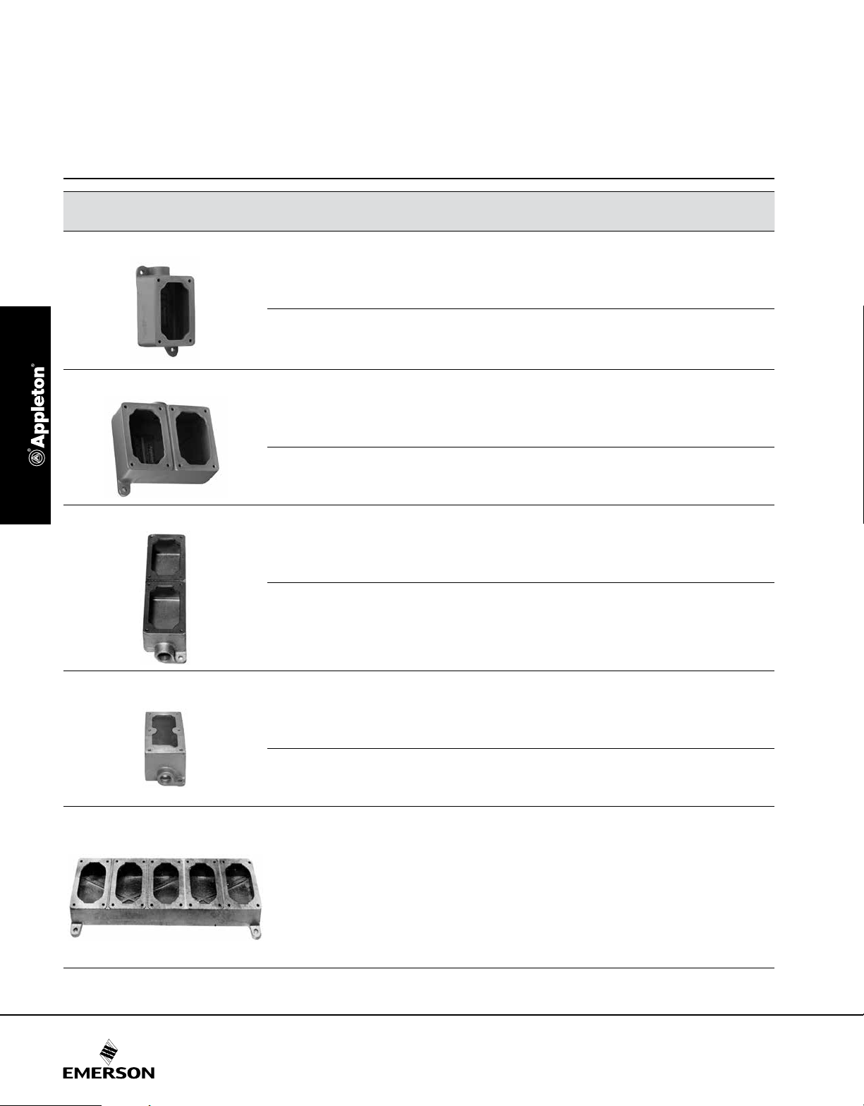
Mounting Bodies
Furnished with Internal Ground Screw.
NEC/CEC:
Class I, Division 1 and 2, Groups C, D
Class II, Division 1 and 2, Groups E, F, G
Class III
NEMA 7CD, 9EFG
1-Gang
2-Gang
Tandem
Type
Dead-End
Feed-Thru
Dead-End
Feed-Thru
Dead-End
Feed-Thru
Hub Size
(Inches)
1/2 EFD150NLQ EFD150ANLQ
3/4 EFD175NLQ EFD175ANLQ
1 EFD110NLQ EFD110ANLQ
1/2 EFDC150NLQ EFDC150ANLQ
3/4 EFDC175NLQ EFDC175ANLQ
1 EFDC110NLQ EFDC110ANLQ
1/2 EFD250NLQ EFD250ANLQ
3/4 EFD275NLQ EFD275ANLQ
1 EFD210NLQ EFD210ANLQ
1/2 EFDC250NLQ EFDC250ANLQ
3/4 EFDC275NLQ EFDC275ANLQ
1 EFDC210NLQ EFDC210ANLQ
1/2 EFDT50NLQ —
3/4 EFDT75NLQ —
1 EFDT10NLQ —
1/2 EFDCT50NLQ —
3/4 EFDCT75NLQ —
1 EFDCT10NLQ —
Malleable Iron Aluminum
Catalog Number
3-Device
1/2 EFDL50Q —
Dead-End
Feed-Thru
Blank Bodies for Brazed Hubs
Construct complete catalog numbers per EFD Cast Device Boxes Ordering Information on following
page. Hubs will be located in center of walls and evenly spaced unless otherwise specified. Where
spacings are critical, submit sketch showing exact spacing requirements.
1-Gang EFD1NL —
2-Gang EFD2NL —
3-Gang EFD3NL —
For tandem bodies, external seals must be installed within 1.5 meters (5 feet) of each conduit entrance for Class I, Groups C and D.
Blank EFD bodies are Non-UL Listed.
4-Gang EFD4NL —
5-Gang EFD5NL —
3/4 EFDL75Q —
1 EFDL10Q —
1/2 EFDCL50Q —
3/4 EFDCL75Q —
1 EFDCL10Q —
22
Page 2
EFD/EFDB and EDS Series Factory Sealed Control Stations
Controls: nEC/CEC Explosionproof Control stations and switChEs
© February 2018
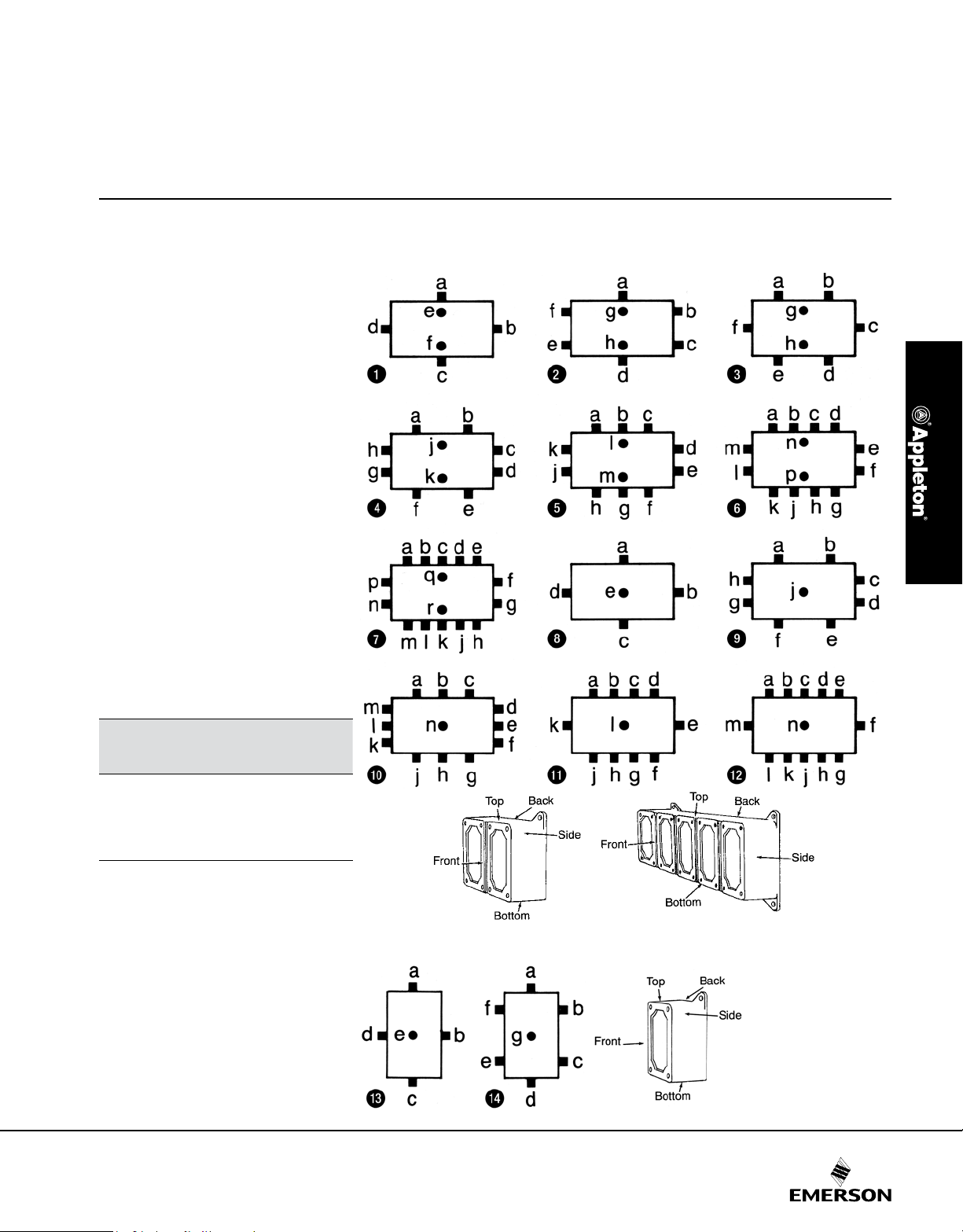
EFD Cast Device Box Ordering Information. Blank Bodies for Brazed Threaded Hubs
1-, 2-, 3-, 4- and 5-Gang Boxes. Brazed Threaded Hubs for Rigid Conduit, 1/2” thru 1”; Brazed Union Hubs, 1/2” thru 1”.
Determine catalog number as follows:
(1) Select EFD device box catalog number;
(2) Select ”Standard Hub Arrangement
Diagram” number; and
(3) Select symbols that represent hub
sizes from ”Symbol Table.” (Use ”0”
where no hub is required, and separate
the various divisions of the complete
catalog number by dashes.)
Example
The blank body device box selected is
EFD3NL and the hub arrangement is
diagram #8. Hub ”a” is to be 3/4” brazed
threaded; hub ”b”, 1” brazed threaded;
hub ”c”, 3/4” brazed threaded; hub ”d”,
no hub is required; and hub ”e”, 1” brazed
union.
The complete catalog number will be:
EFD–3NL–8–23203E
If a ”Standard Hub Arrangement” is not
suitable for the application, or when hubs
are to be more accurately spaced, submit
sketch locating hubs (1) from centerlines
of walls and (2) from outside back of box
(or from mounting lug surface if lugs are
supplied).
All hubs will be located in centerlines of
walls and evenly spaced unless
otherwise specified.
Standard Hub Arrangement Diagrams
Hub ”a” is always TOP of box
2-, 3-, 4- and 5-Gang (Front View)
Symbol Table
Hub Size
(Inches)
Blank 0 0
1/2 1 1E
3/4 2 2E
1 3 3E
Brazed
Threaded Hub
Symbol
Brazed Union
Hub Symbol
1-Gang (Front View)
23
 Loading...