

Appleton Appleton A-51 LED Series Lighting Fixture for Groups C, D, 650590-000 Instruction Sheet

650590-000
INSTRUCTION SHEET
Installation and Maintenance Instructions for the
Appleton™ A-51 LED Series Lighting Fixture
FOR PROPER AND SAFE INSTALLATION OF THIS PRODUCT PLEASE READ THE FOLLOWING INSTRUCTIONS
AND KEEP THIS MANUAL FOR FUTURE REFERENCE.
A-51 LED Series lighting xtures for:
Class I, Division 1, Groups C and D
Class II, Division 1, Groups E, F, and G
WARNING GENERAL
1. DO NOT MODIFY UNIT IN ANY WAY. Modication may
affect safety and reliability.
2. Improper use or failure to follow these instructions
could result in serious injury or property damage.
3. Operator should be instructed in the safe and proper
usage and maintenance of this product.
WARNING ELECTRICAL
1. Disconnect electrical power before installation,
adjustment and maintenance.
2. DO NOT overload; the amperage and voltage indicated
on the nameplate must not be exceeded.
3. Check continuity before connecting electrical power.
4. All installations must comply with applicable local
and/or National Electrical Code®.
5. Before installing check xture unit nameplate and
carton labels to be sure you have correct xture and
mounting hood. Circuit must be deactivated before
installing xture.
CAUTION GENERAL
1. All A-51 LED Series Fixtures are to be mounted
vertically with globe facing down.
The xture unit must be installed with one of the following
mounting hoods for safe operation. Failure to use fixture
unit with one of the following mounting hoods voids
warranty as well as the UL Listing and creates the risk of
re or explosion.
Fixture unit must be installed with:
AAP-50, AAP-75,
AAP-100, AEP-50,
AEP-75, or AEP-100
Pendant Hood
AAC-50, AAC-75,
AAC-100, AEC-50,
AEC-75 or AEC-100
Ceiling Hood
AALB-50, AALB-75,
AALB-100, AELB-50
AELB-75 or AELB-100
Long Wall Bracket Hood
FIXTURE INSTALLATION DIRECTIONS
1. Use the installation drawing as a guide. Install mounting
hood rst as all wiring connections are made in the
mounting hood. The xture unit requires no internal
wiring connections.
• I nstall mounting hood to conduit system (and/or wall,
ceiling or stanchion). If using pendant or stanchion
mounting hood, secure the hood to the conduit system
with the set screw.
2. Remove the connection block (VPT7) from the mounting
hood by loosening (but not removing) the two Phillips head
screws. Turn connection block counter-clockwise to remove.
3. When using ceiling bracket, long wall bracket, or short
wall bracket, mounting hoods, threaded adapter
(59064050000) can be removed by lifting gasket
(59064034000) to access set screw.
• Loosen set screw and turn adapter counter-clockwise for
easier access to junction box. If long bracket (AALB-)
is being used, bracket can be removed from junction box
by loosening set screw in flange and turning
counter-clockwise.
4. Pull supply wires from the conduit into the junction box.
Make connection of supply wires to the VPT-7 connection
block by attaching “HOT” voltage lead to the black wire
and common “neutral” lead to the white wire on the
connection block.
5. Secure threaded adapter (where applicable) or long
bracket (where applicable) to junction box and tighten
all set screws.
6. Secure VPT-7 connection block to threaded adapter or
mounting hood by slipping over Phillips head screws,
turning clockwise and tightening screws.
7. Inspect threads of mounting hoods and the xture unit to be
sure they are clean and free of damage.
• Inspect globe for any chips, scratches or cracks.
CAUTION GENERAL
Chipped, scratched or cracked
globes will fail. Replace any
such defective lamp housing.
8. Thread the fixture unit into mating threads of
mounting hood until tight against gasket of mounting
hood. Locking spring of xture unit should engage with
notches on mounting hood.
9. Install guard and/or reector if desired. Check tightness of
set screws and all threaded joints. Activate supply circuit
to test xture.
MUST BE
FREE OF
CHIPS OR
CRACKS
AASB-50, AASB-75,
AESB-50 or AESB-75
Short Wall
Bracket Hood
Appleton • 1.800.621.1506 • www.appletonelec.com 650590-000 Rev. B 07/17/18 • Page 1 of 8

LONG BRACKET INSTALLATION
1. Remove bracket from junction box, pull through
leads to connector block. Attach ground wire to
grounding screw.
2. Remove Connector block from threaded adapter,
p
ull leads through to connect wires t
wires on block. Black lead is “line” lead and “white”
lead is “neutral.”
3. Push block into place and tighten screws. Install
xture. NOTE: Plugs should be removed and
resealed with pipe sealant.
o correct
#10-24 x 3/8"
SL.RD.HD.
SET
SCREW
JUNCTION
BOX
TLC-3 HERE
59064050000
THREADED ADAPTER
VPT-7 CONNECTOR BLOCK
SCREW #8 -32 x 1/2" PH. HD.
CAUTION:
Disconnect supply circuit before opening xture.
MAINTENANCE DATA
• To maintain maximum light output from this xture, it should be cleaned periodically as follows:
1. Alkaline or acidic cleaners will attack the protective coating of epoxy on the xture and should not be used.
The aluminum exterior of this fixture should be cleaned only with a mild soap or cleaner, and should
be rinsed with water immediately. This will allow the epoxy to protect the xture from corrosive elements in
the atmosphere and result in longer xture life.
2. The glass globe should be cleaned using a soft cloth and a non-abrasive cleaner. The globe should be
regularly inspected for scratches or chips. If the globe is scratched or chipped, it must be replaced.
3. The porcelain enamel reector may be cleaned with any non-abrasive detergent or glass cleaner.
• These periodic cleaning procedures are important to prevent the accumulation of dust and dirt which will
impair the light output of the xture.
• When removing and repairing the xture, lubricate threads only with Appleton TLC-3 conductive, high
temperature lubricant. This should only be necessary if threads are no longer coated with the blue or black
color of the dry lm lubricant.
• See the next page for drawings and a complete parts list.
OPERATIONAL DATA
• The xture must be operated in an environment that does not exceed 55°C.
• The xture may be operated on AC power only up to 277 VAC and 300 VDC.
WARNING:
• To reduce the risk of re or explosion, do not install where the operating temperature exceeds
ignition temperature of hazardous atmospheres.
• Refer to the nameplate on the xture for maximum operating temperature and for proper
fixture classication.
Appleton • 1.800.621.1506 • www.appletonelec.com 650590-000 Rev. B 07/17/18 • Page 2 of 8

A-51 GROUPS C & D LIGHTING FIXTURES FAMILY TREE
MOUNTING HOODS (Use of components marked “Not UL Listed” voids the UL Listing of the assembled xture.)
Pendant Ceiling 25° Stanchion Long Bracket 15° Short Bracket
0ne hub Three close-up plugs One close-up plug Three close-up plugs One close-up plug
1/2" AAP-50, AEP-50 1/2" AAC-50, AEC-50 1-1/2" AAN-150 1/2" AALB-50, AELB-50 1/2" AASB-50, AESB-50
3/4" AAP-75, AEP-75 3/4" AAC-75, AEC-75 (Not UL Listed) 3/4" AALB-75, AELB-75 3/4" AASB-75, AESB-75
1" AAP-100, AEP-100 1" AAC-100, AEC-100 1" AALB-100, AELB-100
HOUSING
ALL1
ALL2
PORCELAIN
REFLECTOR
STANDARD DOME
AARW-15ST
ALUMINUM
GUARD
AAGU-1
PORCELAIN
REFLECTOR
30° ANGLE
AARW-15AN
THREE-WAY EXIT SIGN
IN PLACE OF GUARD
CJEXRN
(Not UL Listed)
SINGLE-SIDED
EXIT SIGN
IN PLACE OF GUARD
AEXR-15R
(Not UL Listed)
Appleton • 1.800.621.1506 • www.appletonelec.com 650590-000 Rev. B 07/17/18 • Page 3 of 8
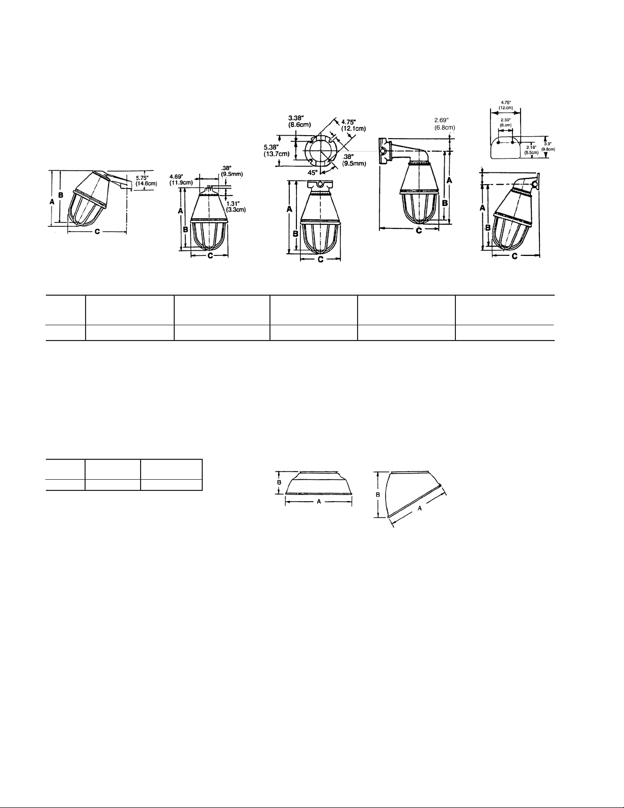
Dimensions: A-51 LED Lighting Fixtures
Dimensions in Inches
Stanchion Pendant Ceiling Long Bracket Short Bracket
Watts A B C A B C A B C A B C A B C
15–25 11.47 10.85 11.50 12.25 11.63 7.06 13.75 13.13 7.06 13.75 13.13 12.38 13.56 12.94 9.13
A-51 Series Reectors
Watts A B A B
STD. DOME 30° ANGLE
15–25 12.00 4.50 10.00 7.63
Except as expressly provided by Appleton Grp, LLC (Appleton), Appleton products are intended for ultimate purchase by industrial users and for operation by persons trained and experienced in the use and maintenance of this equipment
and not for consumers or consumer use. Appleton warranties DO NOT extend to, and no reseller is authorized to extend Appleton’s warranties to any consumer.
While every precaution has been taken to ensure accuracy and completeness in this manual, Appleton Grp, LLC. assumes no responsibility, and disclaims all liability for damages resulting from use of this information or for any errors or
omissions. Specications are subject to change without notice. The Appleton and Emerson logos are registered in the U.S. Patent and Trademark Ofce. All other product or service names are the property of their registered owners.
©2017 Appleton Grp, LLC. All rights reserved.
Appleton • 1.800.621.1506 • www.appletonelec.com 650590-000 Rev. B 07/17/18 • Page 4 of 8

650590-000
FICHE D’INSTRUCTIONS
Instructions d’installation et de maintenance du luminaire
Appleton™ série A-51 LED
POUR UNE INSTALLATION CORRECTE ET EN TOUTE SÉCURITÉ DE CE PRODUIT, VEUILLEZ LIRE LES INSTRUCTIONS
SUIVANTES ET CONSERVER CE MANUEL POUR RÉFÉRENCE ULTÉRIEURE.
Luminaire Appleton™ série A-51 LED pour :
Classe I, Division 1, Groupes C et D
Classe II, Division 1, Groupes E, F et G
AVERTISSEMENT GÉNÉRAL
1. NE PAS MODIFIER L’APPAREIL DE QUELQUE FAÇON
QUE CE SOIT. Toute modication peut affecter la sécurité
et la abilité.
2. Une utilisation incorrecte ou un non-respect de ces
instructions peut causer de graves blessures ou des dommages matériels.
3. L’opérateur doit être formé à l’utilisation et à la maintenance correctes et sûres de ce produit.
AVERTISSEMENT ÉLECTRIQUE
1. Débrancher l’alimentation avant l’installation, le réglage
et la maintenance.
2. NE PAS surcharger; l’intensité et la tension indiquées sur la
plaque signalétique ne doivent pas être dépassées.
3. Vérier la continuité avant de raccorder l’alimentation
électrique.
4. Toutes les installations doivent respecter le code local
et/ou le code national de l’électricité en vigueur.
5. Avant toute installation, consulter la plaque signalétique
et les étiquettes en carton pour s’assurer de disposer du
luminaire et du cône de xation corrects. Le circuit doit
être désactivé avant l’installation du luminaire.
AVERTISSEMENT GÉNÉRAL
1. Tous les luminaires de la série A-51 LED doivent être
montés verticalement avec le globe orienté vers le bas.
Le luminaire doit être installé avec l’un des cônes de fixation
Le luminaire doit être installé avec l’un des cônes de xation
suivants pour un fonctionnement en toute sécurité. Le fait
suivants pour un fonctionnement en toute sécurité. Le fait de
de ne pas utiliser un luminaire avec l’un des cônes de xa-
ne pas utiliser un luminaire avec l’un des cônes de xation
tion suivants annule la garantie et la certication UL et crée un
suivants annule la garantie et la certication UL et crée un
risque d’incendie ou d’explosion.
risque d’incendie ou d’explosion.
Un luminaire doit être installé avec :
Un luminaire doit être installé avec :
Un cône de suspension
AAP-50, AAP-75,
AAP-100, AEP-50,
AEP-75 ou AEP-100
Un cône de xation
au plafond AAC-50,
AAC-75, AAC-100,
AEC-50, AEC-75
ou AEC-100
Un cône à support
mural long AALB-50,
AALB-75, AALB-100,
AELB-50 AELB-75
ou AELB-100
Un cône à support
mural court AASB-50,
AASB-75, AESB-50
ou AESB-75
INSTRUCTIONS D’INSTALLATION DU
LUMINAIRE
1. Utiliser le schéma d’installation comme un guide. Installer
d’abord le cône de xation car tous les raccordements sont
effectués dans le cône de xation. Le luminaire ne requiert
aucun raccordement par câblage interne.
• Installer le cône de xation sur le système de conduite (et/
ou un mur, un plafond ou un tube). Si un cône de fixation sur suspension ou sur tube est utilisé, xer le cône au
système de conduite à l’aide de la vis d’arrêt.
2. Retirer le bloc de connexion (VPT7) du cône de xation en
desserrant (sans retirer) les deux vis cruciformes. Tourner le
bloc de connexion dans le sens inverse des aiguilles d’une
montre pour le retirer.
3. Lors de l’utilisation d’un support de plafond, d’un support mural
long ou court, de cônes de xation, l’adaptateur leté
(59064050000) peut être retiré en soulevant le joint
d’étanchéité (59064034000) pour accéder à la vis d’arrêt.
• Desserrer la vis d’arrêt et tourner l’adaptateur dans le sens
inverse des aiguilles d’une montre pour accéder plus facilement à la boîte de jonction. Si un support long (AALB-) est
utilisé, le support peut être retiré de la boîte de jonction
en desserrant la vis d’arrêt et en le tournant dans le sens
inverse des aiguilles d’une montre.
4. Tirer sur les câbles d’alimentation pour les extraire du conduit
de la boîte de jonction. Raccorder les câbles d’alimentation
au bloc de connexion VPT-7 en reliant le fil de phase au
câble noir et le l neutre au câble blanc du bloc de connexion.
5. Fixer l’adaptateur leté (le cas échéant) ou le support long
(le cas échéant) sur la boîte de jonction et serrer toutes les vis
d’arrêt.
6. Fixer le bloc de connexion VPT-7 sur l’adaptateur leté ou
le cône de xation en le glissant sous la tête des vis cruciformes, en tournant dans le sens des aiguilles d’une montre et
en serrant les vis.
7. Inspecter les letages des cônes de xation et du luminaire
pour s’assurer qu’ils sont propres et en bon état.
• Inspecter le globe à la recherche d’éclats, d’éraures ou de
ssures.
AVERTISSEMENT
GÉNÉRAL
Les globes présentant des éclats,
des éraures ou des ssures
connaîtront une défaillance.
Remplacer de tels boîtiers d’éclairage défectueux.
8.
Visser le luminaire dans le letage correspondant du cône de
xation jusqu’à ce qu’il soit serré contre le joint d’étanchéité
du cône de xation. Le ressort de verrouillage du luminaire doit
s’enclencher dans les encoches du cône de xation.
9. Installer une grille de protection et/ou un réecteur, le cas
échéant. Vérier le serrage des vis d’arrêt et de tous les joints
letés. Activer le circuit d’alimentation pour tester le luminaire.
DOIT ÊTRE
EXEMPT
D’ÉCLATS OU
DE FISSURES
Appleton • 1.800.621.1506 • www.appletonelec.com 650590-000 rév. B 17/07/18 • Page 5 sur 8

INSTALLATION AVEC UN SUPPORT
LONG
1. Retirer le support de la boîte de jonction, insérer des
ls jusqu’au bloc de connexion. Relier le câble de
mise à la terre à la vis de mise à la terre.
2. Retirer le bloc de connexion de l’adaptateur leté.
I
nsérer des ls pour raccorder des câbles a
câbles corrects du bloc. Le l noir est le l de
«phase» et le l blanc est le l «neutre».
3. Pousser le bloc en place et serrer les vis. Installer
le luminaire. REMARQUE : les bouchons doivent
être retirés et à nouveau scellés à l’aide d’un produit
d’étanchéité pour tuyaux.
ux
N° 10-24 x 3/8"
Vis à tête ronde fendue
VIS D’ARRÊT
BOÎTE DE
JONCTION
APPLIQUER DU
LUBRIFIANT TLC-3 ICI
59064050000
ADAPTATEUR FILETÉ
VPT-7 BLOC DE CONNEXION VIS
N° 8 -32 x 1/2" CRUCIFORME
ATTENTION :
débrancher le circuit d’alimentation avant d’ouvrir le luminaire.
DONNÉES DE MAINTENANCE
• Pour maintenir la puissance lumineuse maximale de ce luminaire, le nettoyer périodiquement comme suit:
1. Les produits de nettoyage alcalins ou acides attaquent le revêtement protecteur en résine époxy du luminaire et ne
doivent pas être utilisés. La surface extérieure en aluminium de ce luminaire doit être nettoyée uniquement
avec un savon ou un produit de nettoyage doux et doit être immédiatement rincée avec de l’eau. Cela
permet à la résine époxy de protéger le luminaire contre les éléments corrosifs présents dans l’atmosphère et de
prolonger ainsi sa durée de vie.
2. Le globe en verre doit être nettoyé à l’aide d’un chiffon doux et d’un produit de nettoyage non abrasif. Le
globe doit être régulièrement inspecté à la recherche d’éraures ou d’éclats. Remplacer le globe s’il est éraé ou
ébréché.
3. Le réecteur en émail de porcelaine peut être nettoyé avec tout détergent non abrasif ou produit de nettoyage
pour verre.
• Ces procédures de nettoyage périodiques sont importantes pour éviter l’accumulation de poussière et de
saletés qui dégraderaient la puissance lumineuse du luminaire.
• Lors du retrait et de la réparation du luminaire, lubrier les letages uniquement avec du lubriant haute
température conducteur Appleton TLC-3. Cela n’est nécessaire que si les letages ne sont plus enduits du lubriant à pellicule sèche de couleur bleue ou noire.
• Voir la page suivante pour des schémas et une nomenclature complète.
DONNÉES OPÉRATIONNELLES
• Le luminaire doit être utilisé dans un environnement dont la température ne dépasse pas 55°C.
• Le luminaire peut être utilisé sur une alimentation secteur d’une tension maximale de 277VAC et 300 VDC.
AVERTISSEMENT :
• An de réduire les risques d’incendie ou d’explosion, ne pas installer dans des zones dangereuses dont la
température d’allumage est inférieure à la température de service.
• Consulter la plaque signalétique du luminaire pour connaître la température de service maximale et la classifi-
cation correcte du luminaire.
Appleton • 1.800.621.1506 • www.appletonelec.com 650590-000 rév. B 17/07/18 • Page 6 sur 8

ORGANIGRAMME DE LA FAMILLE DES LUMINAIRES A-51
DES GROUPES C ET D
CÔNES DE FIXATION (l’utilisation de composants marqués « Not UL Listed » [Non certié UL] annule la certication UL du luminaire assemblé).
Montage en suspension Montage sur plafond Montage sur tube incliné à 25° Montage sur support long Montage sur support court incliné à 15°
Un manchon Trois bouchons obturateurs Un bouchon obturateur Trois bouchons obturateurs Un bouchon obturateur
1/2" AAP-50, AEP-50 1/2" AAC-50, AEC-50 1-1/2" AAN-150 1/2" AALB-50, AELB-50 1/2" AASB-50, AESB-50
3/4" AAP-75, AEP-75 3/4" AAC-75, AEC-75 (Non certié UL) 3/4" AALB-75, AELB-75 3/4" AASB-75, AESB-75
1" AAP-100, AEP-100 1" AAC-100, AEC-100 1" AALB-100, AELB-100
BOÎTIER
ALL1
ALL2
RÉFLECTEUR EN
PORCELAINE
DÔME STANDARD
AARW-15ST
GRILLE DE
PROTECTION EN
ALUMINIUM
AAGU-1
RÉFLECTEUR EN
PORCELAINE
ANGLE DE 30°
AARW-15AN
PANNEAU D’ISSUE DE
SECOURS À TROIS FACES
AU LIEU D’UNE GRILLE DE
PROTECTION
CJEXRN
(Non certié UL)
PANNEAU D’ISSUE DE
SECOURS À UNE FACE
AU LIEU D’UNE GRILLE
DE PROTECTION
AEXR-15R
(Non certié UL)
Appleton • 1.800.621.1506 • www.appletonelec.com 650590-000 rév. B 17/07/18 • Page 7 sur 8

Dimensions : luminaires Appleton A-51 LED
Dimensions en pouces
Montage sur tube Montage en suspension Montage sur plafond Montage sur support long Montage sur support court
Watts A B C A B C A B C A B C A B C
15–25 11,47 10,85 11,50 12,25 11,63 7,06 13,75 13,13 7,06 13,75 13,13 12,38 13,56 12,94 9,13
Réecteurs de la série A-51
Watts A B A B
DÔME STANDARD ANGLE DE 30°
15–25 12,00 4,50 10,00 7,63
Sauf disposition contraire expresse d’Appleton Grp, LLC (Appleton), les produits Appleton sont conçus pour un achat par des utilisateurs industriels et pour une utilisation par des personnes qualiées et expérimentées dans l’utilisation et l’entretien de cet équipement, et
non par des clients ou des utilisateurs particuliers. Les garanties Appleton ne s’appliquent PAS à des utilisateurs particuliers, et aucun détaillant n’est autorisé à étendre les garanties Appleton pour quelque consommateur que ce soit.
Bien que toutes les précautions possibles aient été prises pour garantir l’exactitude et l’exhaustivité de ce manuel, Appleton Grp, LLC.décline toute responsabilité quant aux dommages résultant de l’utilisation de ces informations ou aux erreurs ou omissions éventuelles.
Les spécications sont sujettes à modication sans préavis. Les logos Appleton et Emerson sont déposés auprès du bureau des brevets et des marques déposées des États-Unis (U.S. Patent and Trademark Ofce). Tous les autres noms de produits ou de services
appartiennent à leurs propriétaires respectifs.
©2017 Appleton Grp,LLC. Tous droits réservés.
Appleton • 1.800.621.1506 • www.appletonelec.com 650590-000 rév. B 17/07/18 • Page 8 sur 8
 Loading...