

Page 1

Power Mac G4 Quicksilver Teardown
Power Mac G4 Quicksilver Teardown
Tools used in this guide
English size sockets
Flathead Screwdriver
Phillips #0 Screwdriver
Socket Wrench
© 2010 iFixit — CC BY-NC-SA www.iFixit.com Page 1 of 10
Page 2
Power Mac G4 Quicksilver Teardown
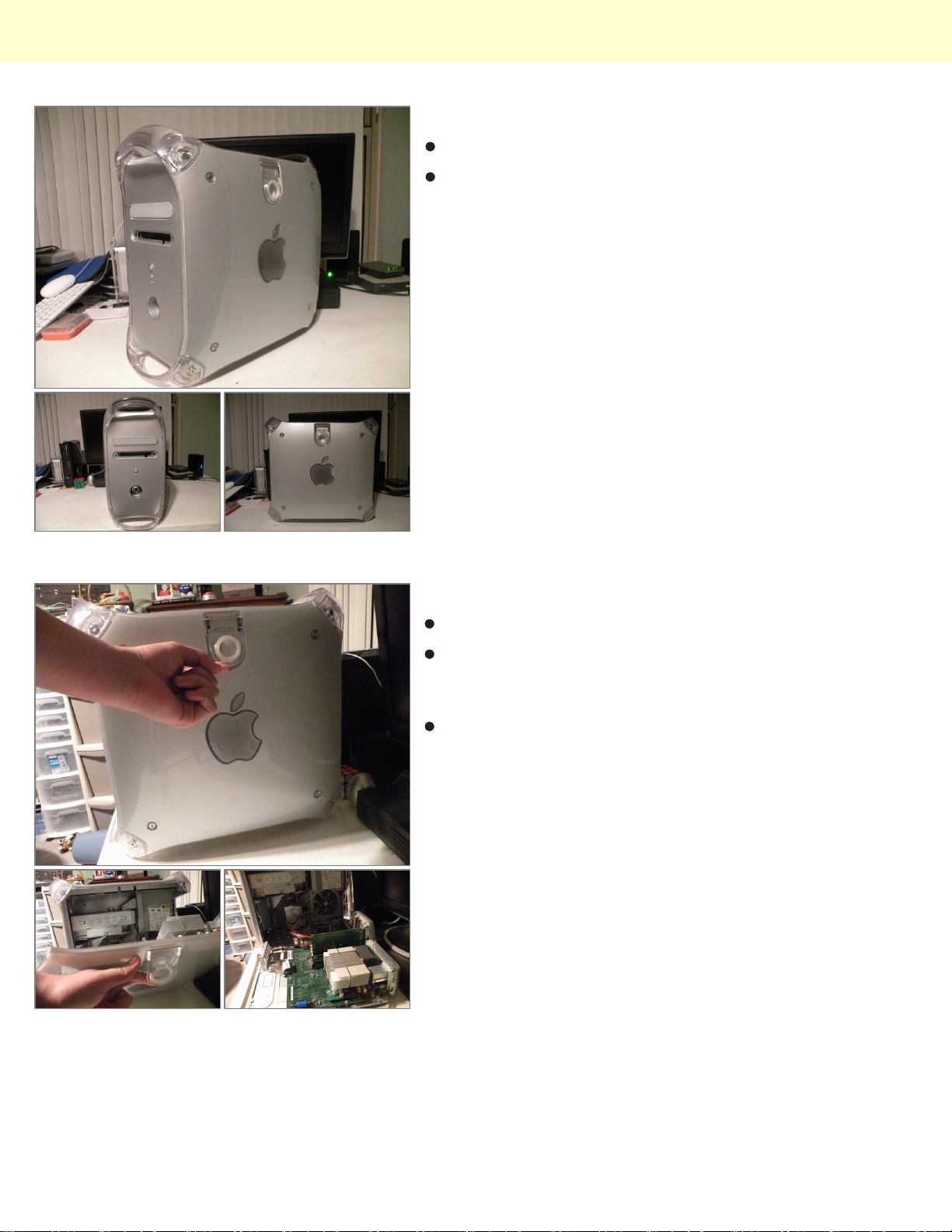
Step 1 -
The Powermac G4 "QuickSilver"
Unfortunately, my zip drive bezel fell off.
Step 2
Start by opening the case.
The same way, the other powermac g3's and G4's
open... Just lift the lever on the side of the case, and
lower it down.
This gives us access to the guts.
© 2010 iFixit — CC BY-NC-SA www.iFixit.com Page 2 of 10
Page 3
Power Mac G4 Quicksilver Teardown
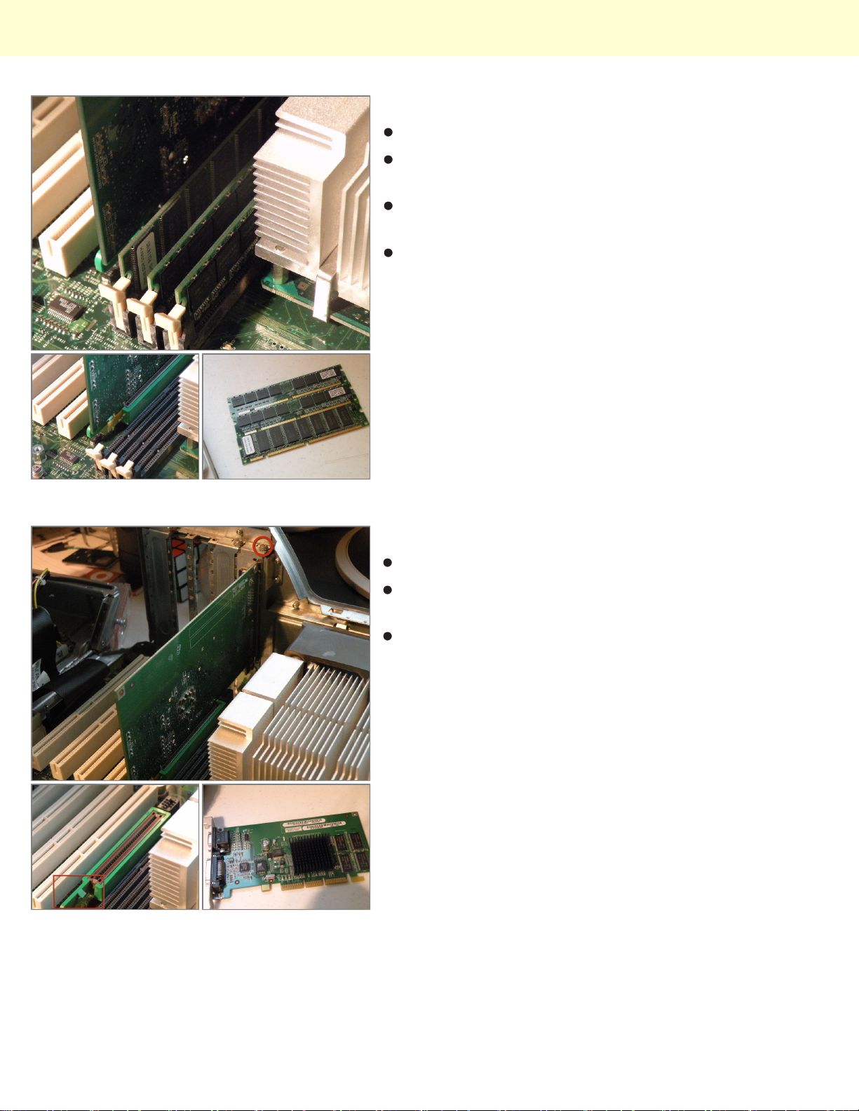
Step 3
Ram
Hidden between the cpu and the graphics card is the
ram.
the quicksilver uses PC133 133Mhz Ram and supports
up to 1.5Gb, just like the cube.
The Original ram is Labeled "KingMax." Some Type of
Kingston Knockoff?
Step 4
The AGP Graphics Card:
Remove this screw, then push in this tab outward, and
pull the card out.
The Quicksilver came standard with this card, a 32MB
NVIDIA GeForce 2MX AGP Mac Edition, this card
supports the ADC Displays like the one we took apart
last week.
© 2010 iFixit — CC BY-NC-SA www.iFixit.com Page 3 of 10
Page 4
Power Mac G4 Quicksilver Teardown
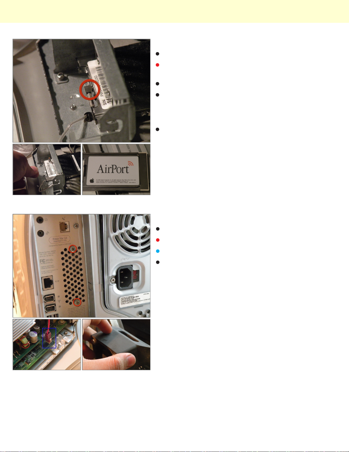
Step 5
AirPort Card:
Remove the AirPort Antenna by pulling it out of the
back of the card
Grab the plastic tab, and pull the card out.
This is the same PCMCIA 802.11b Airport card found in
every mac from 2000-2004, it is only wireless "B" so
you only get 11Mbps, but that is enough for web
browsing.
This Space Intentionatly Left Blank
Step 6
Removing The CPU Fan:
Remove these 2 Phillips screws.
Then Remove the fan connector.
Then, remove the fan.
© 2010 iFixit — CC BY-NC-SA www.iFixit.com Page 4 of 10
Page 5
Power Mac G4 Quicksilver Teardown
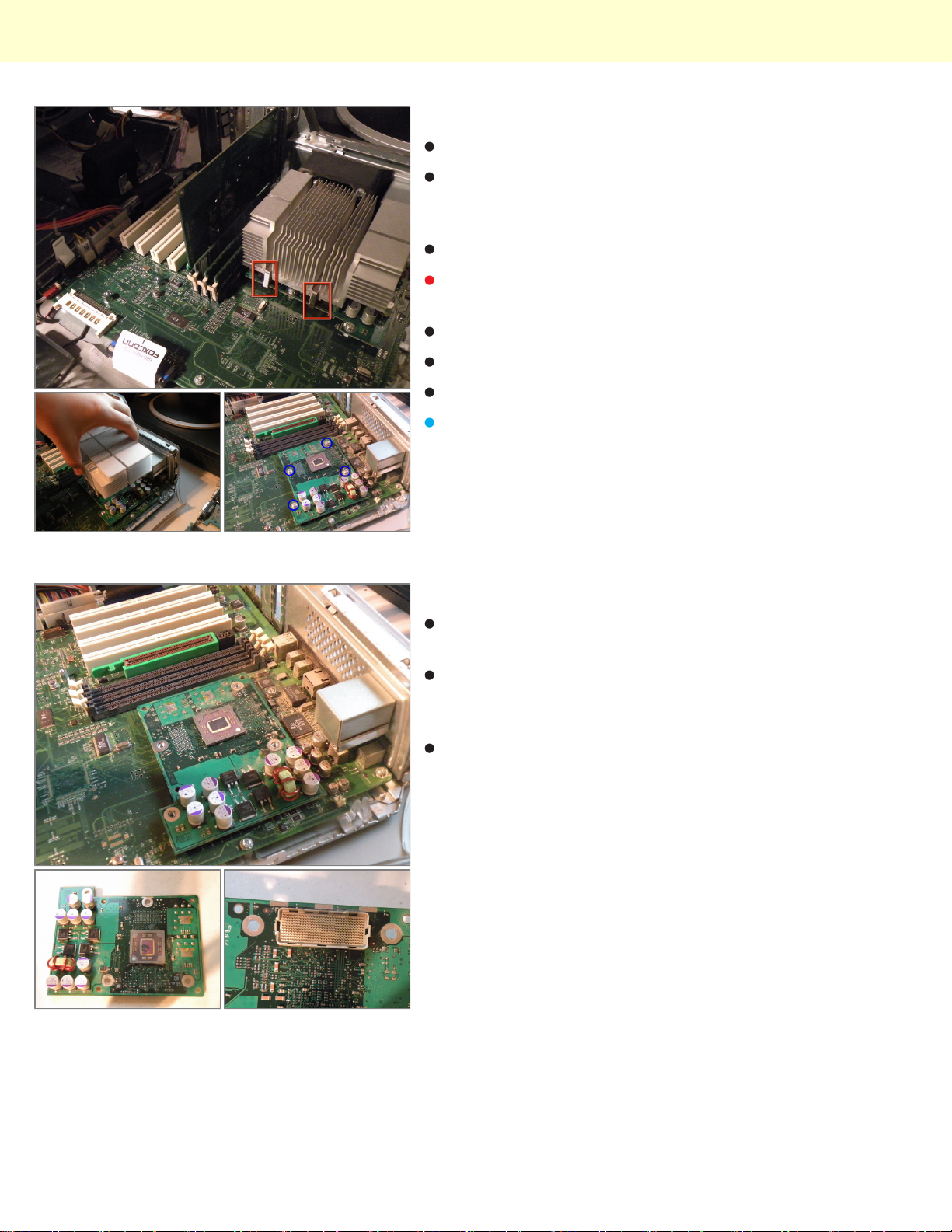
Step 7
CPU:
This Computer boasts a 733Mhz Motorola PowerPC
G4 CPU, though not fast enough to run leopard
natively, it runs 10.4.11 "Tiger" fine.
It has a 733Mhz Motorola PowerPC 7450 (G4).
Start by removing the heatsink clamps with a flathead
screwdriver.
Do the same for the other side.
Then Lift off the heatsink.
This will reveal the CPU.
Remove these screws.
Step 8
Once those screws are removed, carefully remove the
CPU.
This is apple's 300-Pin connector, it is found on this
Mac, and MDD's (This cpu won't work in an MDD) and
similar to the one in PowerMac G5's.
This connector is incredibly hard to remove, because of
the way it connects, it is also very hard to remove
without damaging it, if you don't pull it straight up, you
will, most likely damage it.
© 2010 iFixit — CC BY-NC-SA www.iFixit.com Page 5 of 10
Page 6
Power Mac G4 Quicksilver Teardown
Step 9
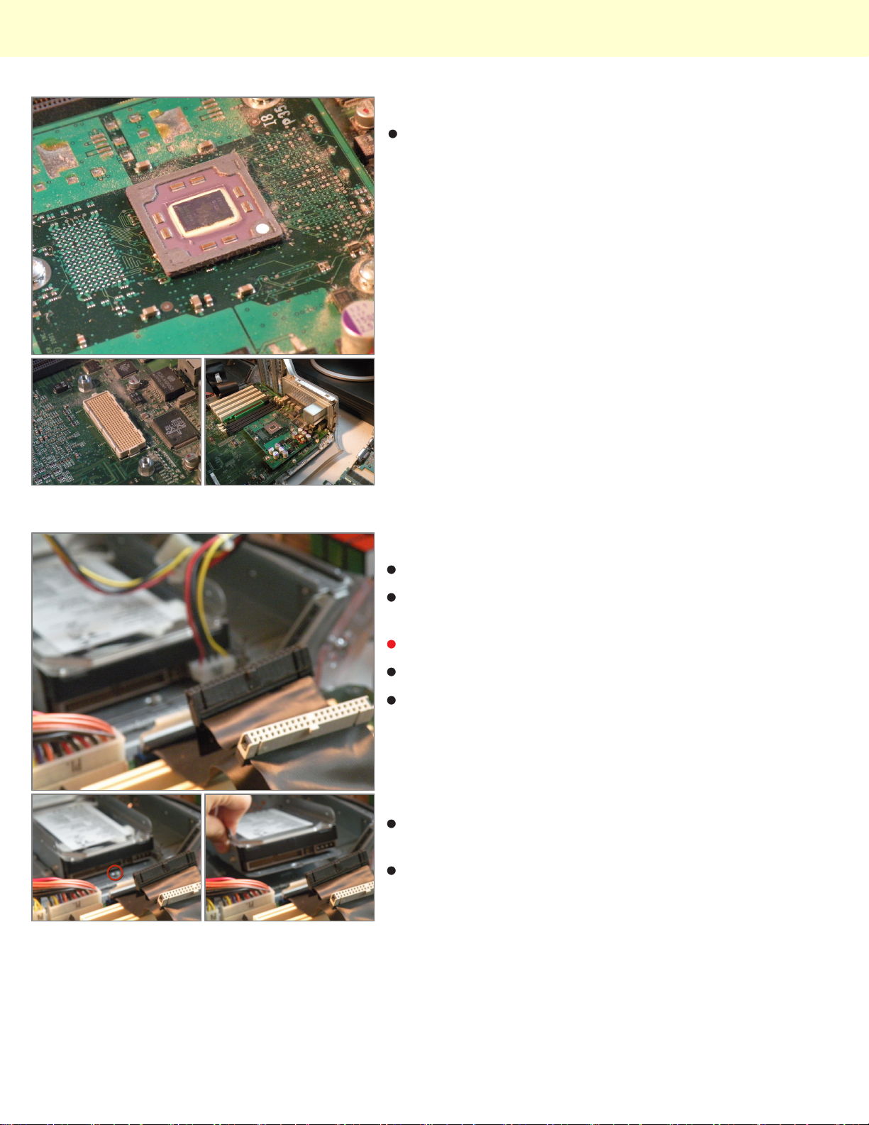
More CPU Shots:
Step 10
The Hard Drive Caddy:
Disconnect the IDE Cable and Power Cables from any
hard drives.
Remove this screw if present.
Slide the caddy out, then set it aside.
Many Apple Computers Including earlier versions of
this one had a 128GB Limit on hard drives, only
Quicksilvers made in 2002 and later will support hard
drives larger than 128GB, but to bypass this, simply
partition your hard drive in to multiple partitions under
128GB in Disk Utility.
This computer uses standard IDE hard disks, and
originally shipped with 40GB or 80GB.
It will support up to 4 IDE drives, 2 Hard Disks, one
Optical Drive, and one ZIP Drive.(You can put an IDE
Hard Disk in the the ZIP Drive Slot if you wish, allowing
for 3 Hard Drives).
© 2010 iFixit — CC BY-NC-SA www.iFixit.com Page 6 of 10
Page 7
Power Mac G4 Quicksilver Teardown
Step 11
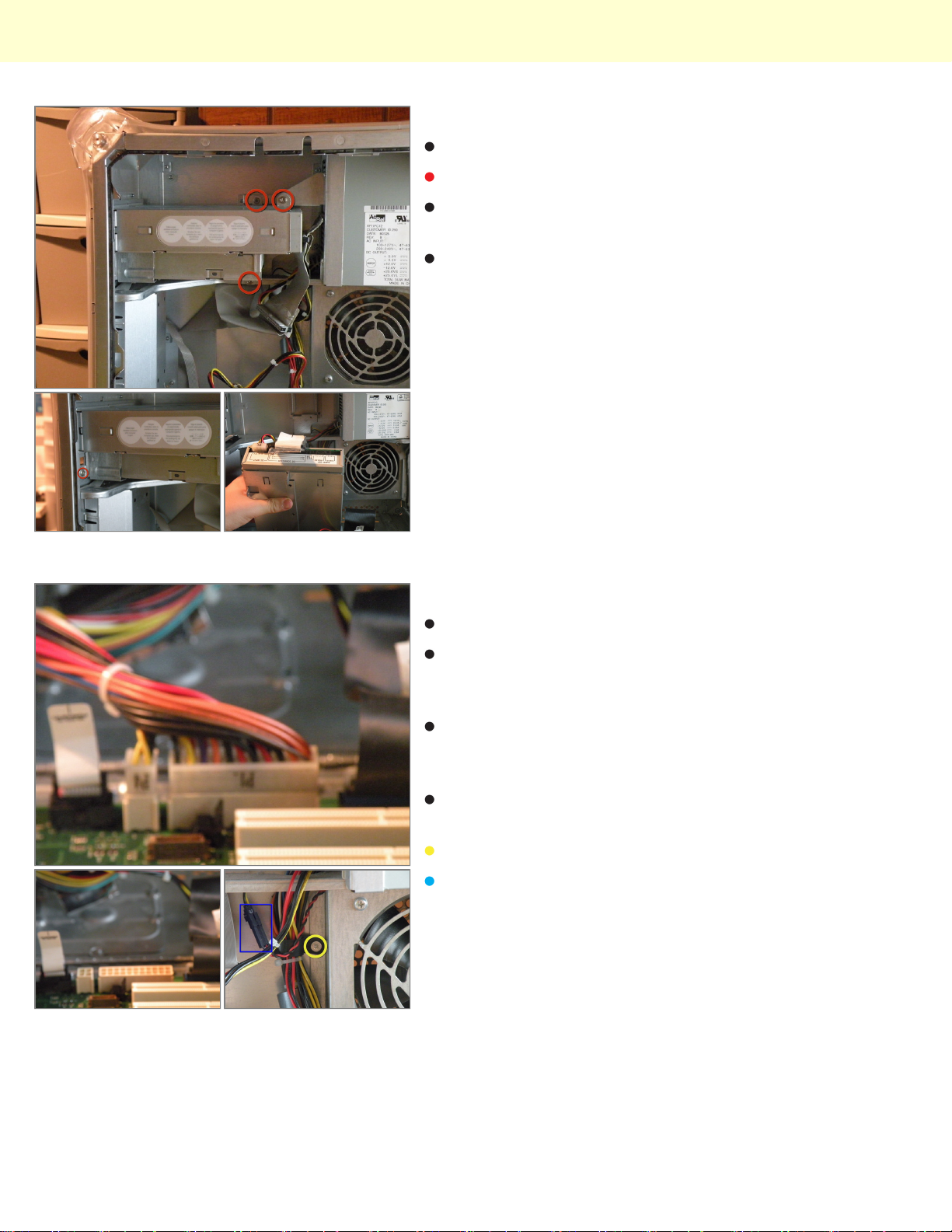
Optical Drive / Zip Drive Cage:
Start by removing all of these screws.
Then Slide the drive cage back, and pull it partially, tha
remove the IDE And Power Cables, and set it aside.
Most Quicksilvers, Including Mine Shipped Standard
With a DVD/CD-RW "ComboDrive"
Step 12
Power Supply:
This computer uses a non-standard 22-Pin Apple
power supply, plus a 4-Pin 12V connector commonly
found in some power supplies.
Start by disconnecting the power connectors from the
motherboard, and routeing them up to the level of the
power supply.
Also remove the fan connector, and route that up as
well.
Remove this Screw as well.
The Fan Connector:
© 2010 iFixit — CC BY-NC-SA www.iFixit.com Page 7 of 10
Page 8
Power Mac G4 Quicksilver Teardown
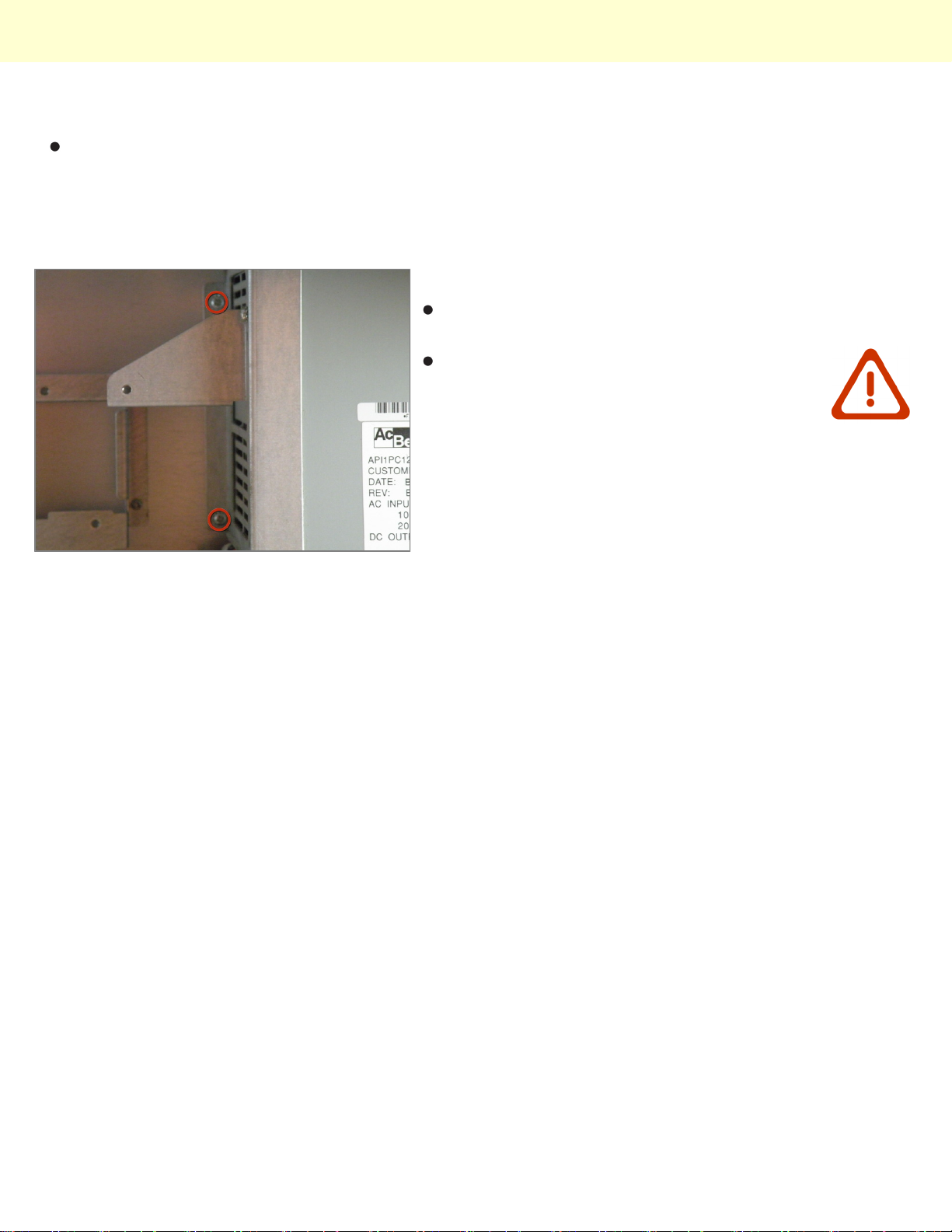
Step 13
Fan removal is only three screws. The one circled in
yellow, one on the upper left of the frame cage (not
show), and one on the middle bottom of the frame (not
shown).
Step 14
Now, remove these 2 screws, and slide the power
supply out of the case.
This isn't a standard PC Power Supply like
the one in the G3 Blue And White,
attempting to use an ATX PC Power Supply
will fry the logic board!
© 2010 iFixit — CC BY-NC-SA www.iFixit.com Page 8 of 10
Page 9
Power Mac G4 Quicksilver Teardown
Step 15
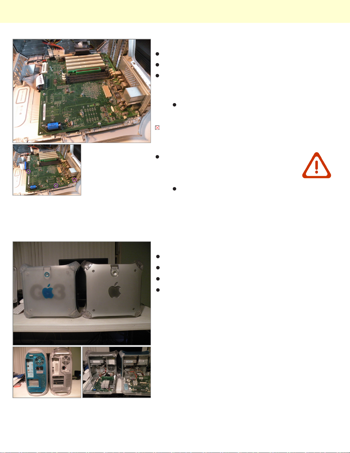
Removing the logic board
start by disconnecting everything, cables, battery, etc.
There are three hex-shaped screws holding the board, which are
right where the CPU was. These also provide the screw holes to
screw and hold the CPU. Use an English size socket to remove
these three screws left behind from the CPU.
then remove the 4 screws which are located around the edge of
the board. If you have less than 4 screws, don't worry too much, if
you don't have trouble removing the board at the next step, then
you are fine.
REMEMBER TO GROUND YOURSELF!
I used a metric size socket(I believe it was 7mm), as I did
not have an English size handy, and the metric seemed to
work fine.
Now, slide the logic board away from the rear of the case
about 1/2 inch, and lift it out. It should not be difficult to pull
out or up, if it is, go back, and make sure you have removed
all screws. I did, however, have to pull out towards the front,
then up, then back towards the back of the case before I
could completely remove the board.
Step 16
Comparison to the G3 Blue & White
G4 Quicksilver (Left) (3rd Photo)
G3 B&W (Right) (3rd Photo)
The computers are exactly the same size, but the
Quicksilver Weighs more than the G3, due to heavier
plastics, more case metal, and a much larger heatsink.
© 2010 iFixit — CC BY-NC-SA www.iFixit.com Page 9 of 10
Page 10

Power Mac G4 Quicksilver Teardown
Step 17
Standard PC Parts That Will Work In This Computer:
PC133 133Mhz Ram
Standard IDE Hard Drives
Standard IDE Optical Drives, Even DVD-Burning
"SuperDrives"
To reassemble your device, follow these instructions in reverse order.
© 2010 iFixit — CC BY-NC-SA www.iFixit.com Page 10 of 10
 Loading...