

Page 1
Power Macintosh G3 Blue and White Teardown
Power Macintosh G3 Blue and White Teardown
Tools used in this guide
Flathead Screwdriver
Phillips #0 Screwdriver
Step 1 -
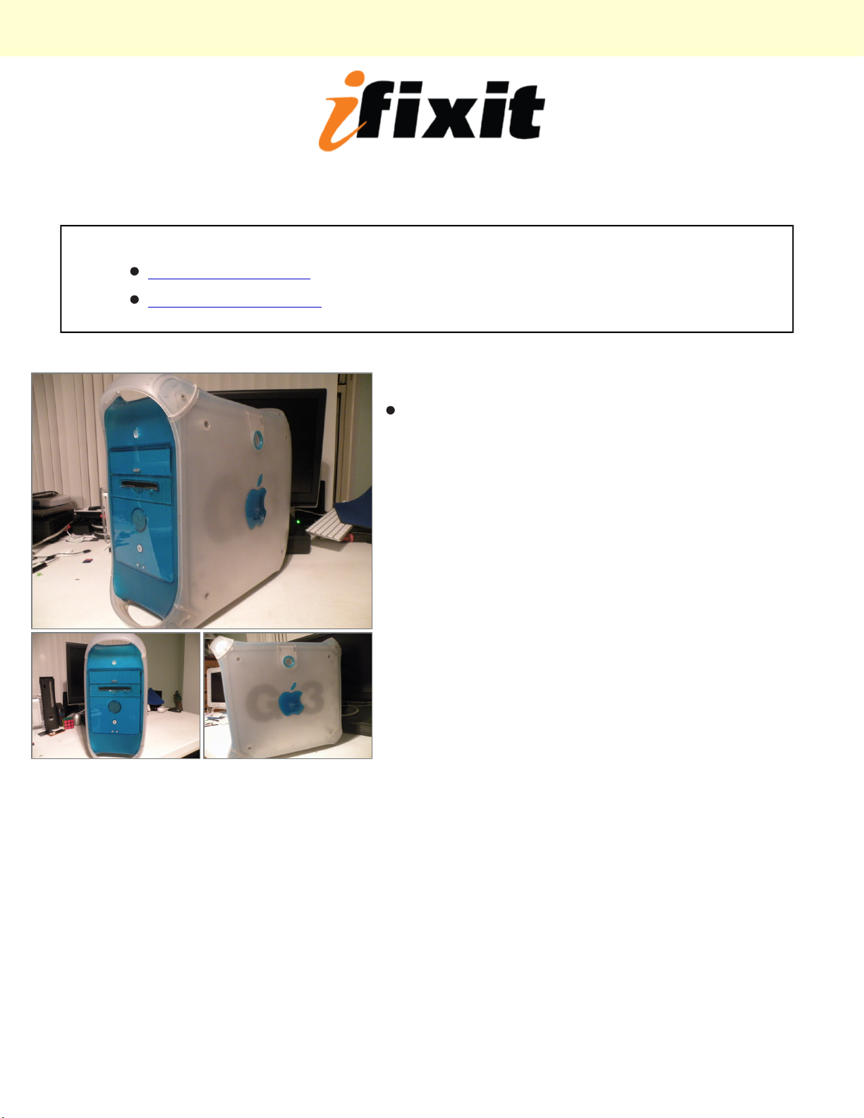
The Powermac G3 Blue And White
© 2010 iFixit — CC BY-NC-SA www.iFixit.com Page 1 of 8
Page 2
Power Macintosh G3 Blue and White Teardown
Step 2
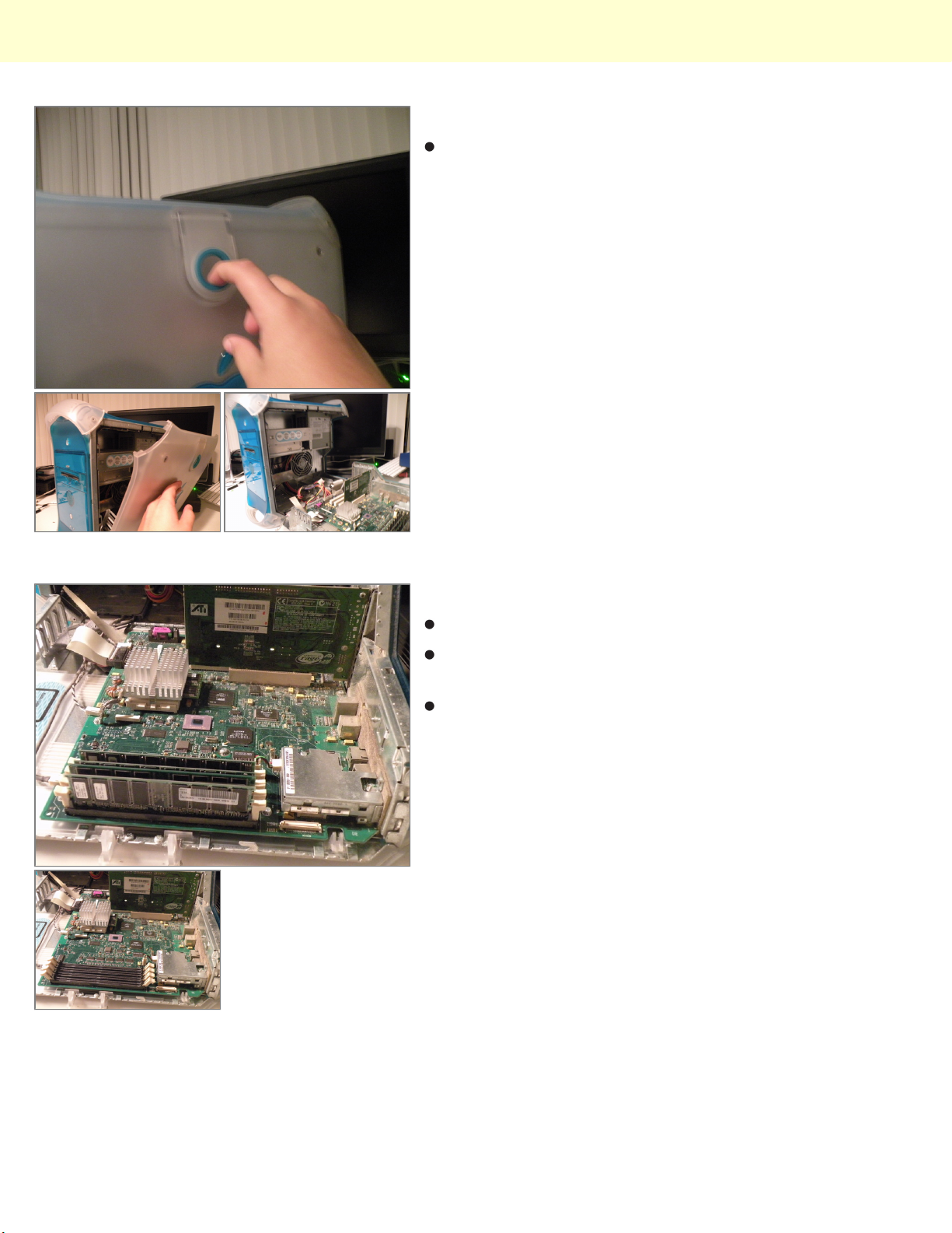
Start By Disconnecting the computer, and lifting the tab
on the side of the computer, and lowering the side
panel.
Step 3
Ram
The PowerMac G3 B&W supports up to 512MB of
PC133 Ram
It has 4 ram slots for an optimal configuration of 4X
128MB
© 2010 iFixit — CC BY-NC-SA www.iFixit.com Page 2 of 8
Page 3
Power Macintosh G3 Blue and White Teardown
Step 4
Removing The CPU
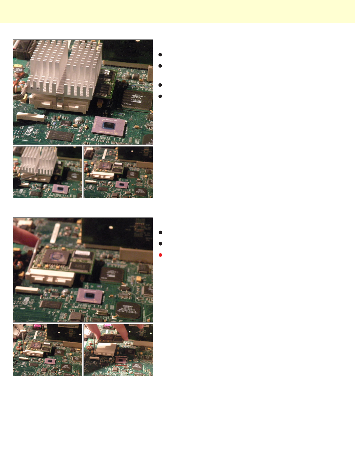
Start by using a flathead to gently pry off the clip,
remember you have to put it back on again!
Then, remove the heatsink.
This reveals the Motorola PowerPC G3 CPU, this is the
400Mhz Model.
Step 5
Then, lift the metal retaining lever.
Then, lift the CPU out of it's socket.
This is the Motorola Co-Processor.
© 2010 iFixit — CC BY-NC-SA www.iFixit.com Page 3 of 8
Page 4
Power Macintosh G3 Blue and White Teardown
Step 6
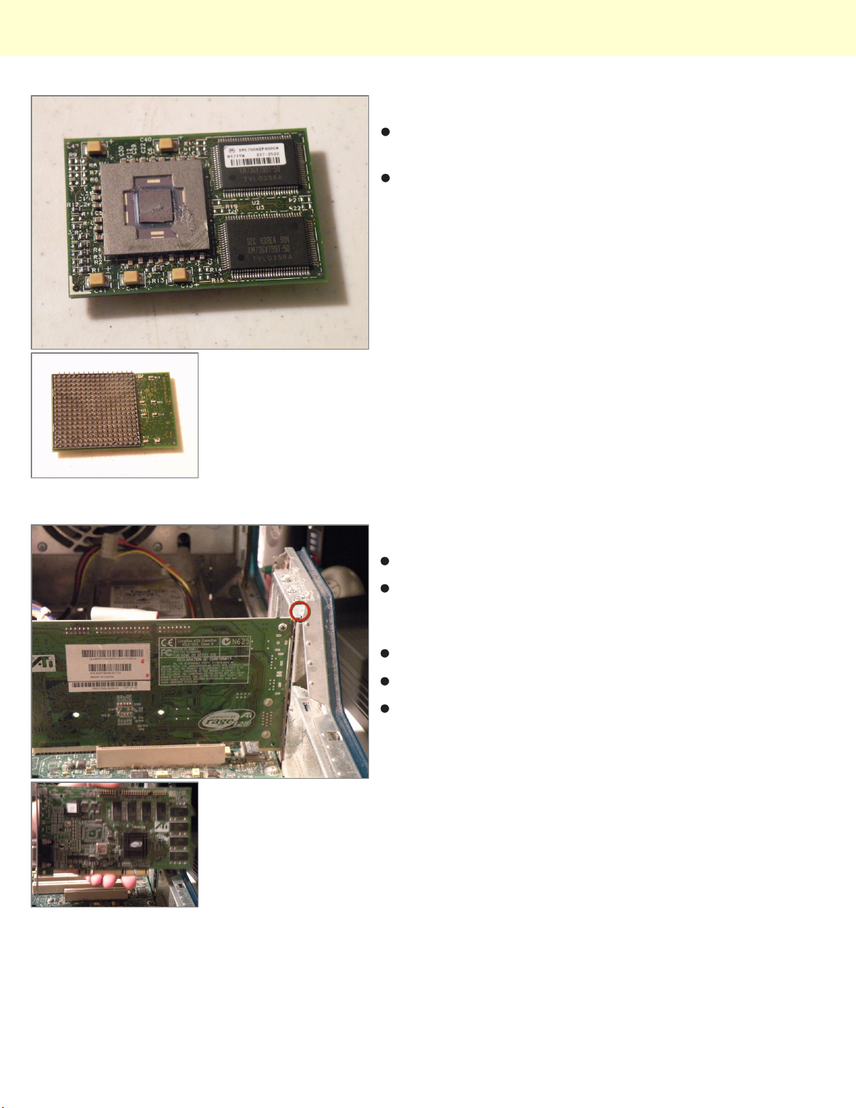
The CPU: A Motorola XPC750MIP400CM (400Mhz
PowerPC 750/G3) With 1Mb Of Level 2 Cache.
This is another one of those unique apple connectors, it
it is a 288 pin keyed PGA socket.
Step 7
Graphics Card:
The Powermac G3 Came Standard With A 16MB ATI
3D Rage PCI Mac Edition Card, there are only a few
available upgrade cards.
Start By Removing this Screw.
Once that's done, pull the card out.
Sorry Guys, Regular PCI Cards Won't work here, only
Mac Edition PCI-Compatible Cards, and this card won't
work in a PC, Also, graphics cards only work in the first
slot, the other 4 PCI Slots won't support graphics cards.
© 2010 iFixit — CC BY-NC-SA www.iFixit.com Page 4 of 8
Page 5
Power Macintosh G3 Blue and White Teardown
Step 8
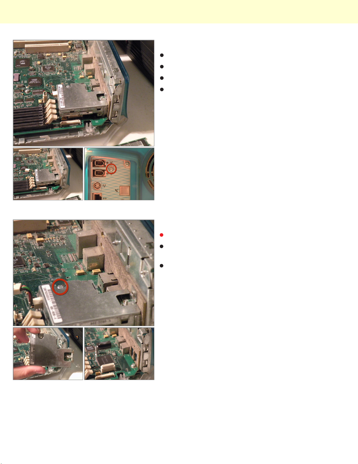
Firewire Module:
Unplug the power cable from the logic board.
Then close the case and remove this screw.
Then open it again.
Step 9
Then remove this screw too.
Then lift the module out, there is a connector
undernieth it, to be careful while doing this.
Then we can move on.
© 2010 iFixit — CC BY-NC-SA www.iFixit.com Page 5 of 8
Page 6
Power Macintosh G3 Blue and White Teardown
Step 10
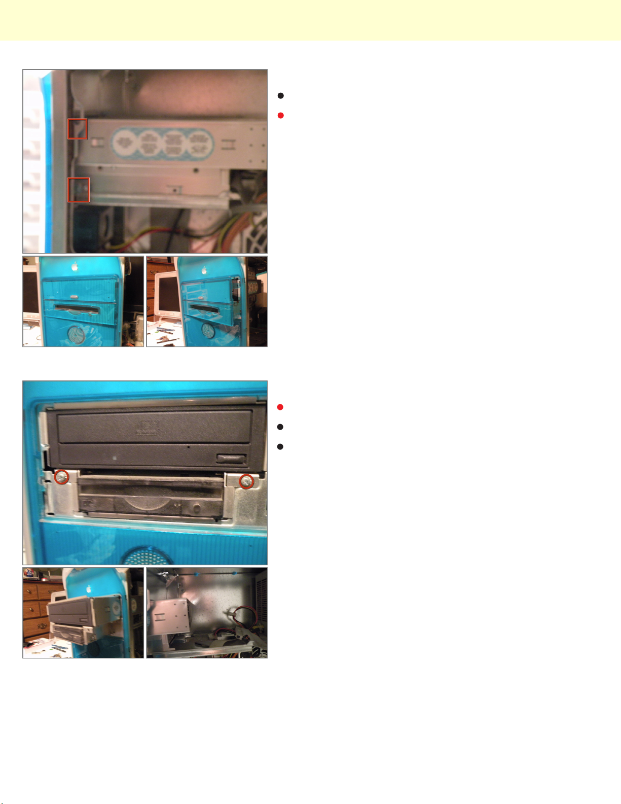
Removing the Optical Drive/ZIP Drive Caddy:
Start by pushing in these tabs, and pulling the blue
drive bezel out.
Step 11
This will reveal 2 phillips screws.
Remove them.
Then push the back of the cage out the front of the
case far enough to remove the ribbon and power
cables, than slide the cage completly out, and set it
aside.
© 2010 iFixit — CC BY-NC-SA www.iFixit.com Page 6 of 8
Page 7
Power Macintosh G3 Blue and White Teardown
Step 12
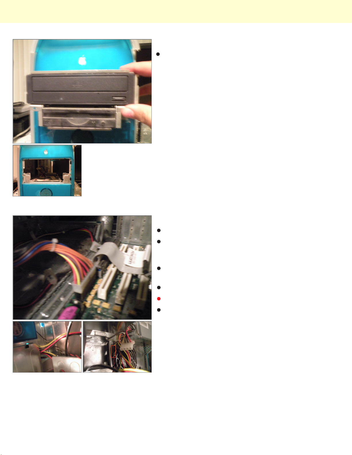
Removing the drive cage:
Step 13
Removing the power supply
Disconnect the power connector from the logic board
(this looks alot like a standard ATX connector, but I
have yet to test the voltages)
There is a 4-Pin Cable connected to the front panel
box, remove it.
Disconnect the internal fan cable.
The Fan Connector
Then Route all of the cables up through the case to the
level of the power supply.
© 2010 iFixit — CC BY-NC-SA www.iFixit.com Page 7 of 8
Page 8
Power Macintosh G3 Blue and White Teardown
Step 14
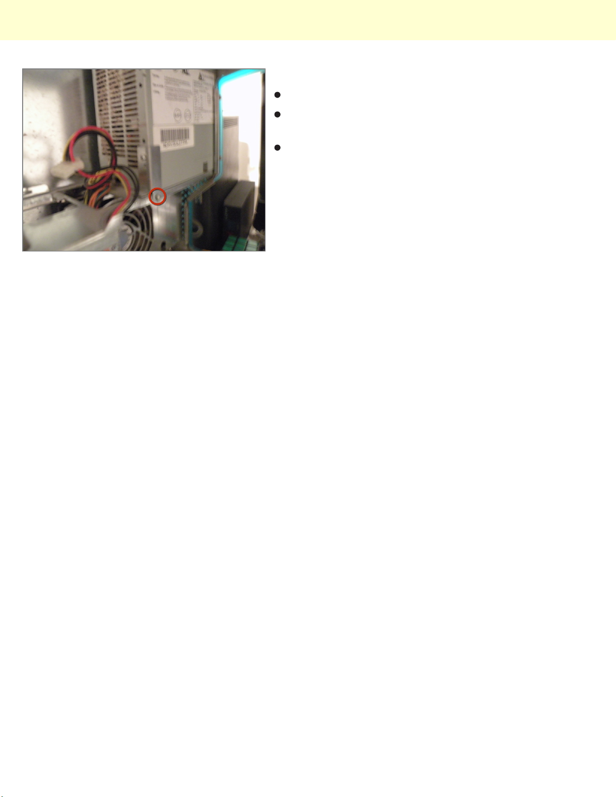
Remove these phillips screws.
Now, you can slide the power supply towards you, and
remove it.
Sorry, but my camera battery died, I will post photos on
how to remove the logic board after I take them
© 2010 iFixit — CC BY-NC-SA www.iFixit.com Page 8 of 8
 Loading...