

Page 1
K
Service Source
Macintosh Portrait Display
Page 2
K
Service Source
Basics
Macintosh Portrait Display
Page 3

Basics International “Series B” - 1
International “Series B”
Apple produced domestic and international versions of the
Portrait Display. The troubleshooting and repair procedures
differ for each version of the monitor. This manual covers
the domestic version only. For documentation on the Portrait
Display “Series B,” refer to the international manual.
Page 4
Basics Monitor Distortion - 2
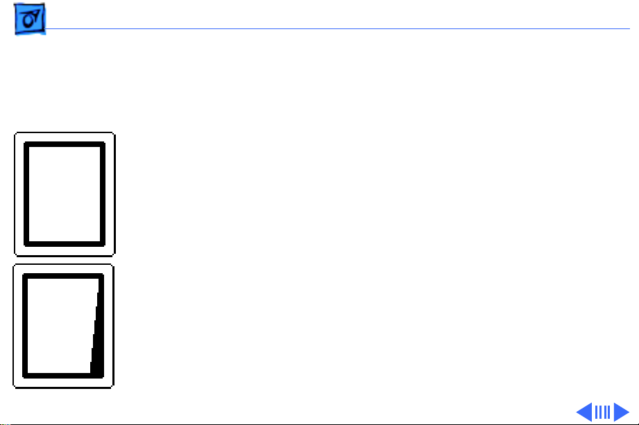
Monitor Distortion
Overview
All large-screen monitors are susceptible to distortions
caused by environmental conditions. These distortions are
Ideal Raster
usually not visible on monitors with smaller screens.
Right Edge
Not Straight
Important:
appear distorted when set up in a new environment.
Common environmentally-caused distortions are shown on
this and the following pages. Always check first for
environmental causes before attempting to repair or adjust
a monitor with a distorted raster.
Even monitors set to factory specifications may
Page 5
Basics Monitor Distortion - 3
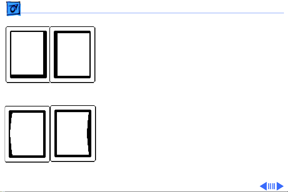
Environmental Influences
The following environmental conditions may distort the
raster of a Portrait Display:
• Proximity to metal objects, such as metal desks, file
cabinets, and bookshelves. Metal objects affect the
earth’s magnetic field. Earth magnetism usually distorts
Raster Shifted
Up and Left
Raster Shifted
Right
only the edges of the screen.
• Fluorescent lights, other monitors, or electronic
appliances such as coffee makers and copy machines.
These objects cause dynamic raster distortion, that is,
movement or jitter of the image.
Left Side
Bowed Out
Right Side
Bowed In
Page 6
Basics Monitor Distortion - 4
Troubleshooting
Upper-Right Corner
Rounded
S-Shaped
Left Edge
Raster Tilted
Right
Important:
Module swapping cannot fix a monitor with
environmental distortion problems, and adjusting a monitor
with such problems alters the factory settings.
Note:
If the monitor has shifted up/down or right/left only,
go ahead and adjust it using the centering controls. However,
keep in mind that if you then move the monitor you may need
to readjust the centering controls.
Before adjusting a monitor with a distorted raster, try the
following:
• Swivel or move the monitor, or
• Remove the monitor from the building and recheck it in
another location.
Page 7

Basics Monitor Distortion - 5
If the display changes (for better or worse) when you move
it to another location, the environment is the source of the
problem. Relocate the monitor or remove the distortioncausing object.
If the display does not change when you move it to another
location, continue troubleshooting the problem (refer to
Troubleshooting/Symptom Charts).
Page 8
K
Service Source
Specifications
Macintosh Portrait Display
Page 9

Specifications Characteristics - 1
Characteristics
Picture Tube
Screen Resolution
Scan Rates
15-in. diagonal screen
Phosphor EIA Type P4 (white)
Flat, square, high-contrast, antiglare surface
640x870; 80 dpi
Analog 1-, 2-, 4-, or 8-bit pixel depth; permits 256 grays at
8 bits/pixel
Vertical refresh rate: 75 Hz
Horizontal scan rate: 68.85 kHz
Dot clock: 52 MHz
Page 10

Specifications Characteristics - 2
Active V ideo Display Area
Input Signal
8 in. by 10.87 in. (203 mm by 276 mm)
Video: analog; RS-343 standard
Page 11

Specifications Controls and Ports - 3
Controls and Ports
User Controls
I/O Ports
Rear panel: power switch
Right side: brightness and contrast controls
Three Apple Desktop Bus (ADB) connectors
Page 12

Specifications Physical and Electrical - 4
Physical and Electrical
Power Supply
Size and Weight
Universal power supply
Voltage: 90–270 VAC, self-configuring
Frequency: 47–63 Hz
Power: 75 W maximum
Height: 13.1 in. (332 mm)
Width: 11.5 in. (292 mm)
Depth: 14.9 in. (379 mm)
Weight: 35 lb. (16 kg)
Page 13

Specifications Operating Environment - 5
Operating Environment
Temperature
Humidity
Altitude
50°F–95°F (10°C–35°C)
90% maximum, noncondensing
10,000 ft. (3,048 m) maximum
Page 14

K
Service Source
Troubleshooting
Macintosh Portrait Display
Page 15

Troubleshooting General/ - 1
General
The Symptom Charts included in this chapter will help you
diagnose specific symptoms related to your product. Because cures
are listed on the charts in the order of most likely solution, try
the first cure first. Verify whether or not the product continues to
exhibit the symptom. If the symptom persists, try the next cure.
(Note: If you have replaced a module, reinstall the original module
before you proceed to the next cure.)
If you are not sure what the problem is, or if the Symptom Charts
do not resolve the problem, refer to the Flowchart for the product
family.
For additional assistance, contact Apple Technical Support.
Page 16

Troubleshooting Symptom Charts/No Raster - 2
Symptom Charts
No Raster
No raster, LED off 1 Ensure monitor’s video cable is connected to the computer or
the video card in the computer.
2 Check power cord connections.
3 Check internal power connections.
4 Replace blown fuse.
5 Replace power/sweep board.
6 Replace video board.
Page 17

Troubleshooting Symptom Charts/No Raster
(Continued)
- 3
No Raster
No raster, LED on 1 Ensure monitor’s video cable is connected to the computer or
the video card in the computer.
2 Adjust brightness and contrast knobs.
3 Verify that video card in computer is working properly.
4 Perform video adjustments.
5 Check internal power connections.
6 Replace power/sweep board.
7 Replace CRT board.
8 Replace video board.
9 Replace CRT.
(Continued)
Page 18
Troubleshooting Symptom Charts/Geometry - 4
Geometry
Raster not centered 1 Verify that distortion is not due to environmental conditions.
Move monitor to another location.
2 Perform horizontal or vertical center adjustments.
3 Replace power/sweep board.
4 Replace CRT.
Raster bulges along
top of screen
Raster stretched or
compressed at top
1 Verify that distortion is not due to environmental conditions.
Move monitor to another location.
2 Replace CRT.
1 Verify that distortion is not due to environmental conditions.
Move monitor to another location.
2 Perform vertical-linearity adjustment.
3 Replace power/sweep board.
4 Replace CRT.
Page 19

Troubleshooting Symptom Charts/GeometryÊ
(Continued)
- 5
Raster short (less
than 10 7/8 in. high)
Raster narrow (less
than 8 in. wide)
Raster bowed or
barrel-shaped
Geometry
1 Perform vertical-height adjustment.
2 Replace power/sweep board.
3 Replace CRT.
1 Perform horizontal-size adjustment.
2 Replace power/sweep board.
3 Replace CRT.
1 Verify that distortion is not due to environmental conditions.
Move monitor to another location.
2 Perform video adjustment.
3 Replace power/sweep board.
4 Replace CRT.
(Continued)
Page 20

Troubleshooting Symptom Charts/GeometryÊ
(Continued)
- 6
Raster pyramid
shaped (or inverted
pyramid)
Geometry
Replace CRT.
(Continued)
Page 21

Troubleshooting Symptom Charts/Video Display - 7
Video Display
Picture is too dark or
too bright
Out of focus 1 Perform focus adjustments.
1 Adjust contrast and brightness knobs.
2 Verify that video card in computer is working properly.
3 Perform video adjustments.
4 Replace CRT board.
5 Replace video board.
6 Replace contrast/brightness board.
7 Replace CRT.
2 Replace power/sweep board.
3 Replace CRT.
Page 22

Troubleshooting Symptom Charts/Synchronization - 8
Synchronization
Picture rolls
vertically
One thin, bright,
horizontal line
appears on screen
Picture breaks into
diagonal lines
1 Verify that video card in computer is working properly.
2 Replace power/sweep board.
1 Replace power/sweep board.
2 Replace CRT.
1 Connect another monitor to computer and verify video signal.
2 Replace power/sweep board.
Page 23

Troubleshooting Symptom Charts/Miscellaneous - 9
Miscellaneous
Black spots on screen
(burnt phosphors)
Picture jitters or
flashes
Intermittently shuts
down
Replace CRT.
1 Check all ground cable connections.
2 Verify that adjacent computer equipment is properly
grounded. Move electrical devices away from monitor and
shut off fluorescent lights in area.
3 Replace power/sweep board.
1 Ensure monitor’s video cable is connected to the computer or
the video card in the computer.
2 Replace power/sweep board.
Page 24

K
Service Source
T ak e Apart
Macintosh Portrait Display
Page 25

Take Apart Rear Cover - 1
Rear Cover
Rear Cover
No preliminary steps are
required before you begin
this procedure.
Warning:
contains high voltage and a
high-vacuum picture tube.
To prevent serious injury,
review CRT safety in
Bulletins/Safety.
This product
Page 26
Take Apart Rear Cover - 2
Remove the four case screws
and lift the rear cover off
the bezel.
Page 27
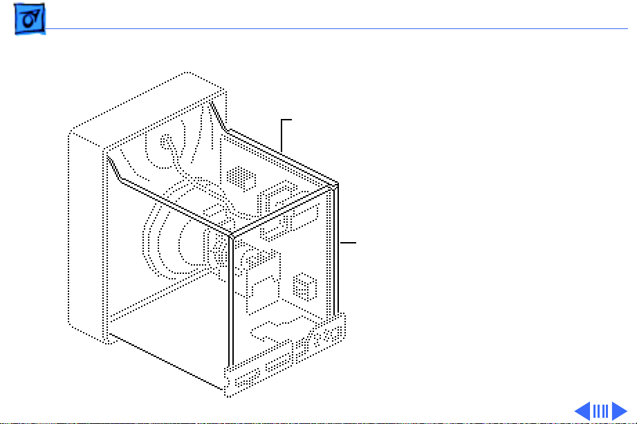
Take Apart EMI Shield - 3
EMI Shield
Before you begin, remove
EMI Shield
the rear cover.
EMI
Shield
Warning:
contains high voltage and a
high-vacuum picture tube.
To prevent serious injury,
review CRT safety in
Bulletins/Safety.
Note:
includes two metal panels at
the top and rear of the
monitor chassis. To repair
the monitor, remove both
panels.
This product
The EMI shield
Page 28
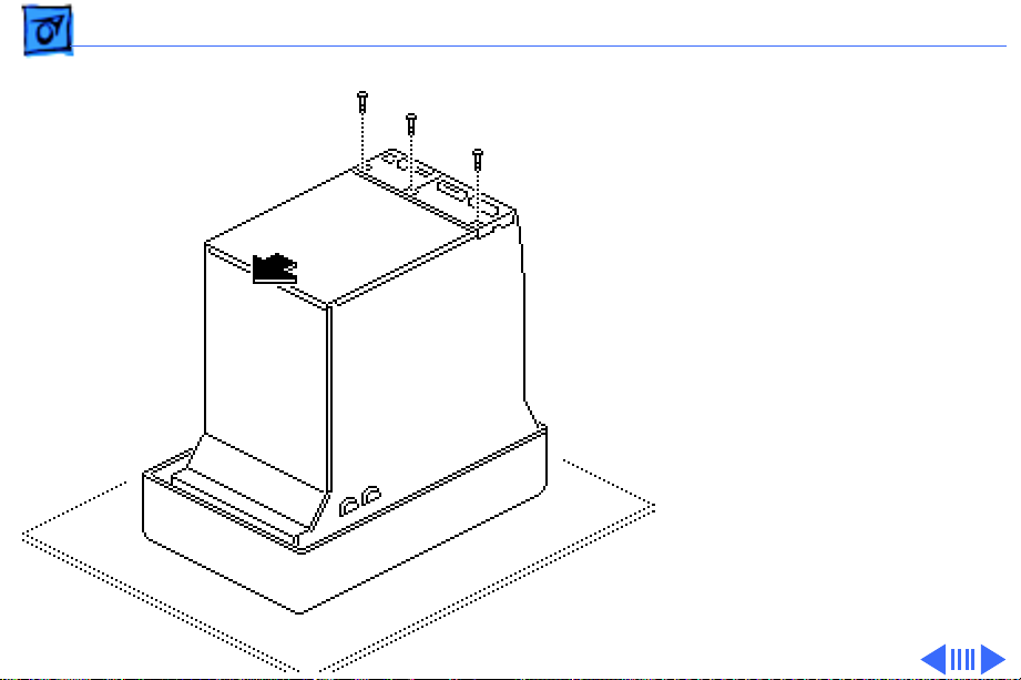
Take Apart EMI Shield - 4
1 Remove the three screws
from the rear panel of
the EMI shield.
2 Slide the rear panel
forward; then lift the
rear panel off the
chassis.
Page 29
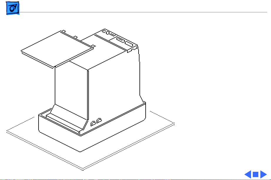
Take Apart EMI Shield - 5
3 Pull up and remove the
top panel from the
chassis.
Page 30
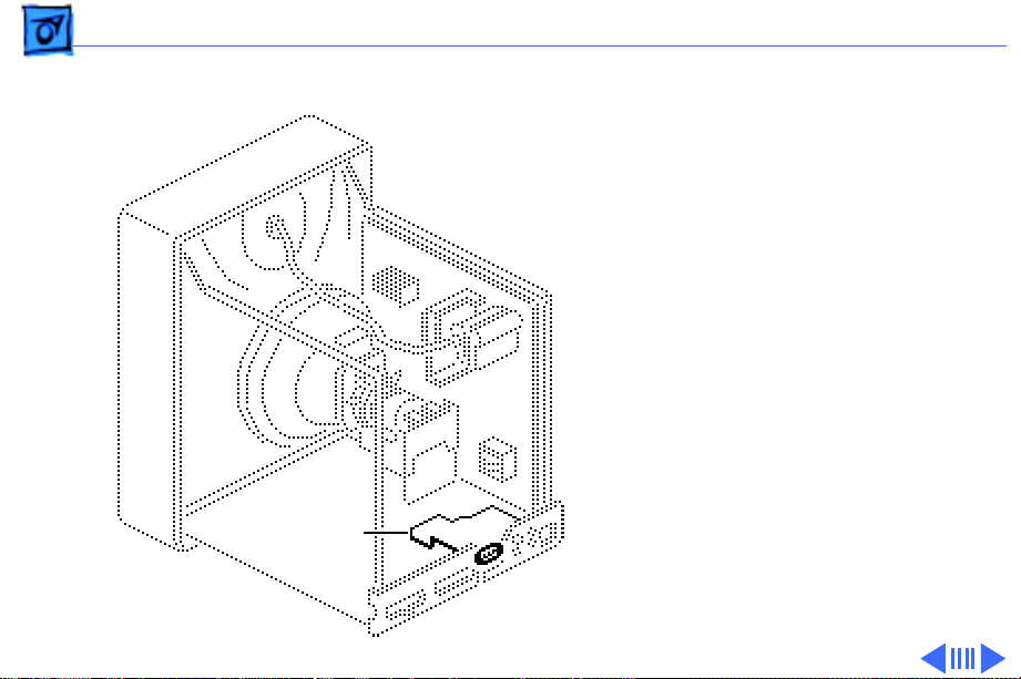
Take Apart AC Input Assembly - 6
AC Input Assembly
Before you begin,
• Remove rear cover
• Remove EMI shield
• Discharge CRT
AC Input
Assembly
Warning:
contains high voltage and a
high-vacuum picture tube.
To prevent serious injury,
review CRT safety in
Bulletins/Safety.
This product
Page 31

Take Apart AC Input Assembly - 7
1 Remove the screw that
secures the black
ground wire to the AC
input assembly
mounting bracket. Push
P Connector
the ground wire through
the hole in the mounting
bracket.
Ground Wire
2 Lift the AC input
assembly from the
chassis and disconnect
the P connector from
the power/sweep board.
Note:
Stop here if you are
removing the AC input
assembly to access another
component.
AC Input Assembly
Page 32

Take Apart AC Input Assembly - 8
3 Cut the tie-wrap and
remove the P connector
from the AC input
assembly. Keep the P
Plastic Knob
Tie-Wrap
P Connector
connector.
4 Pull the plastic knob off
the On/Off switch. Keep
the knob.
Replacement Note:
When
returning a defective AC
input assembly, remove and
keep the plastic On/Off
knob, the P connector, and
the fuse. Install these items
on the replacement
assembly.
Page 33

Take Apart Fuse - 9
Fuse
Before you begin,
• Remove rear cover
• Remove EMI shield
• Discharge CRT
• Remove AC input
assembly
Fuse
Warning:
contains high voltage and a
high-vacuum picture tube.
To prevent serious injury,
review CRT safety in
Bulletins/Safety.
This product
Page 34

Take Apart Fuse - 10
Using your fingers or a flatblade screwdriver, gently
pry up one end of the fuse
and lift out the fuse.
Page 35

Take Apart Signal Input Assembly - 11
Signal Input Assembly
Before you begin,
• Remove rear cover
• Remove EMI shield
• Discharge CRT
Signal Input
Assembly
Warning:
contains high voltage and a
high-vacuum picture tube.
To prevent serious injury,
review CRT safety in
Bulletins/Safety.
This product
Page 36

Take Apart Signal Input Assembly - 12
1 Loosen the screw at the
upper corner of the
video board assembly and
remove the black ground
cable.
2 Disconnect the black
video cable (with the
attached ground cable)
and the 4-wire cable
from the video board.
3 Remove the video cable
Video Cable
and the 4-wire cable
from the two cable
clamps.
Page 37

Take Apart Signal Input Assembly - 13
4 Loosen the screw on the
signal input assembly
mounting bracket and
remove the black ground
cable.
5 Remove the signal input
assembly from the
chassis.
Signal Input
Assembly
Page 38

Take Apart Fan - 14
Fan
Before you begin,
• Remove rear cover
Fan
• Remove EMI shield
• Discharge CRT
Warning:
contains high voltage and a
high-vacuum picture tube.
To prevent serious injury,
review CRT safety in
Bulletins/Safety.
This product
Page 39

Take Apart Fan - 15
1 Open the four cable
clamps.
2 Remove the screw that
secures the fan mounting
bracket to the chassis.
Remove the mounting
bracket, fan, and wire.
3 Disconnect the fan wires
at the fan connector and
remove the fan from the
mounting bracket.
Note
: Stop here if you are
removing the fan assembly
to access another component.
Fan Connector
Page 40

Take Apart Fan - 16
4 Remove the two screws
and lockwashers that
secure the fan to the
mounting bracket.
5 Remove the fan from the
mounting bracket.
Page 41

Take Apart Video Board - 17
Video Board
Before you begin,
• Remove rear cover
• Remove EMI shield
Video Board
• Discharge CRT
• Remove signal input
assembly
• Remove fan
Warning:
contains high voltage and a
high-vacuum picture tube.
To prevent serious injury,
review CRT safety in
Bulletins/Safety.
This product
Page 42

Take Apart Video Board - 18
1 Remove these
connectors from the
video board:
• 3-wire connector S
• 5-wire connector H
• 4-wire connector O
• 6-wire connector C
• 3-wire connector K
2 Remove all connector
wires from cable
clamps.
3 Loosen the retaining
screw on the video board
case and remove the
black ground cable.
Ground Cable
Retaining Screw
Page 43

Take Apart Video Board - 19
4 Pull open the left chassis
panel to access the two
cables at the bottom of
the video board.
5 Remove the video cable
from the cable clamp
beneath the video board
case and disconnect the
cable from the video
board.
6 Disconnect the small LED
LED Connector
connector from the
video board.
Video
Cable
Page 44

Take Apart Video Board - 20
7 Remove the mounting
screw and the video
board case from the
chassis.
8 Remove the video board
mounting screw through
the back of the video
board case.
Page 45

Take Apart Video Board - 21
9 Remove the plastic cable
clamp from the bottom of
the video board case.
10 Depress the three plastic
clips and lift the video
board out of the case.
Cable Clamp
Page 46

Take Apart Contrast Brightness Board - 22
Contrast
Contrast Brightness
Board
Brightness Board
Before you begin,
• Remove rear cover
• Remove EMI shield
• Discharge CRT
Warning:
contains high voltage and a
high-vacuum picture tube.
To prevent serious injury,
review CRT safety in
Bulletins/Safety.
This product
Page 47

Take Apart Contrast Brightness Board - 23
1 Disconnect the C
connector from the
Control Knobs
contrast brightness
board.
2 Remove the mounting
screw from the contrast
brightness board.
3 Pull off the two control
knobs and remove the
contrast brightness
board. Keep the knobs to
Mounting
Screw
install on the
replacement board.
Page 48

Take Apart CRT Board - 24
CRT Board
Before you begin,
• Remove rear cover
• Remove EMI shield
• Discharge CRT
• Remove AC input
assembly
• Remove signal input
assembly
CRT Board
Warning:
contains high voltage and a
high-vacuum picture tube.
To prevent serious injury,
review CRT safety in
Bulletins/Safety.
This product
Page 49

Take Apart CRT Board - 25
1 Loosen the screw on the
Video Board Case
video board case and
remove the black ground
cable.
2 Remove the video cable
from the cable clamp
Ground Cable
beneath the video board
case and disconnect the
cable from the video
board.
Video Cable
Page 50

Take Apart CRT Board - 26
3 Pull open the right
chassis panel enough to
gain access to the upper
connectors on the CRT
board.
4
Caution:
CRT is easily damaged.
Do not apply force to the
neck of the CRT when
removing connectors
from the CRT board.
Support the CRT board
with one hand and
disconnect the 2-wire
4-pin connector F, and
the 3-wire connector K.
The neck of the
Page 51

Take Apart CRT Board - 27
5 Remove the cables and
the ferrite ring from the
cable clamp beneath the
CRT board.
Cable Clamp
Ferrite
Ring
Page 52

Take Apart CRT Board - 28
6 Loosen the screw on the
ring clamp that secures
the CRT board to the neck
of the CRT.
7
Caution:
Twisting,
bending, or applying
force to the CRT board
could damage the neck of
the CRT. Pull the CRT
board straight off the
Metal
Cover
neck of the CRT.
Grasp the metal cover
that protects the CRT
board and carefully pull
the board straight off the
CRT.
Page 53

Take Apart CRT Board - 29
8 Disconnect the following
cable connectors from
the bottom of the CRT
board:
• 4-wire connector O
• 4-wire connector T
• 5-wire connector D
Page 54

Take Apart CRT Board - 30
9 Using needlenose pliers,
remove the plastic
standoff from the bottom
of the metal cover. Keep
the standoff and use it to
install the replacement
CRT board.
10 Slide the CRT board out
of the metal cover. Keep
the cover for installation
on the replacement CRT
board.
Page 55

Take Apart Power/Sweep Board - 31
Power/Sweep Board
Power/Sweep
Board
Before you begin,
• Remove rear cover
• Remove EMI shield
• Discharge CRT
• Disconnect anode cap
• Remove AC input
assembly
Warning:
contains high voltage and a
high-vacuum picture tube.
To prevent serious injury,
review CRT safety in
Bulletins/Safety.
This product
Page 56

Take Apart Power/Sweep Board - 32
1 Disconnect the following
connectors from the
power/sweep board:
• 2-wire connector T
• Single connector GB
2 Unravel the GB
connector cable from
the large red anode cable.
Anode Cable
Page 57

Take Apart Power/Sweep Board - 33
3 Disconnect the fan cable
at the fan connectors.
Fan Cable
Connectors
Fan
Anode Cable
Cable Clamps
4 Remove the fan cable
and the large red anode
cable from the three
cable clamps.
Page 58

Take Apart Power/Sweep Board - 34
5 Pull open the right
chassis panel.
6 Disconnect the following
connectors from the
power/sweep board:
• 8-wire connector H
• 5-wire connector D
• 2-wire connector F
• 4-wire connector M
7 Remove the screw that
secures the black
ground cable to the top of
the chassis.
Page 59

Take Apart Power/Sweep Board - 35
8 Remove the two screws
with captive
lockwashers from the
outside of the right
chassis panel.
9
Note:
Do not attempt to
remove the power/
sweep board from its
plastic cover. When
returning a defective
power/sweep board to
Apple, return the board
and cover as a unit.
Depress the release latch
and pull the power/
sweep board off the
chassis.
Page 60

Take Apart Bezel - 36
Bezel
Bezel
Before you begin,
• Remove rear cover
• Remove EMI shield
• Discharge CRT
Warning:
contains high voltage and a
high-vacuum picture tube.
To prevent serious injury,
review CRT safety in
Bulletins/Safety.
This product
Page 61

Take Apart Bezel - 37
1 With the monitor face-
down on a protective pad,
remove the four screws
that secure the bezel to
the chassis.
Page 62

Take Apart Bezel - 38
2 Set the monitor upright
on a protective pad.
3 Slightly lift the chassis
and pull off the top and
then the bottom of the
bezel.
Page 63

Take Apart LED Cable Assembly - 39
LED Cable Assembly
Before you begin,
• Remove rear cover
• Remove EMI shield
• Discharge CRT
• Remove bezel
LED Cable Assembly
Warning:
contains high voltage and a
high-vacuum picture tube.
To prevent serious injury,
review CRT safety in
Bulletins/Safety.
This product
Page 64

Take Apart LED Cable Assembly - 40
1 Disconnect the small LED
connector from the
bottom of the video
board. Remove the LED
cable from the cable
clamp.
LED Connector
Page 65

Take Apart LED Cable Assembly - 41
2 With the monitor face-
down on a protective pad,
pull the small LED cable
connector from the
chassis access hole.
3 Remove the screw that
secures the LED
mounting bracket to the
LED Cable
Connector
chassis.
Page 66

Take Apart LED Cable Assembly - 42
4 Remove the screw from
the LED board.
5 Cut the tie-wrap and
remove the LED cable
assembly from the
mounting bracket.
Mounting
Bracket
Tie-Wrap
LED Cable
Page 67

Take Apart CRT - 43
CRT
Before you begin,
• Remove rear cover
• Remove EMI shield
• Discharge CRT
• Remove anode cap
• Remove AC input
assembly
CRT
• Remove signal input
assembly
• Remove CRT board
• Remove bezel
• Remove LED assembly
Page 68

Take Apart CRT - 44
Anode
Cable
Cable Clamp
CRT Cable
Warning:
This product
contains high voltage and a
high-vacuum picture tube.
To prevent serious injury,
review CRT safety in
Bulletins/Safety.
1 Disconnect the 4-wire
CRT connector M, and the
single-wire connector
GB from the power/
sweep board.
2 Remove the CRT cable
from the cable clamp at
the bottom of the chassis
and unwrap the GB cable.
Page 69

Take Apart CRT - 45
3 Remove and discard the
copper tape from both
sides of the CRT and
chassis. (Two new strips
of copper tape ship with
the replacement CRT.)
Copper
Tape
Page 70

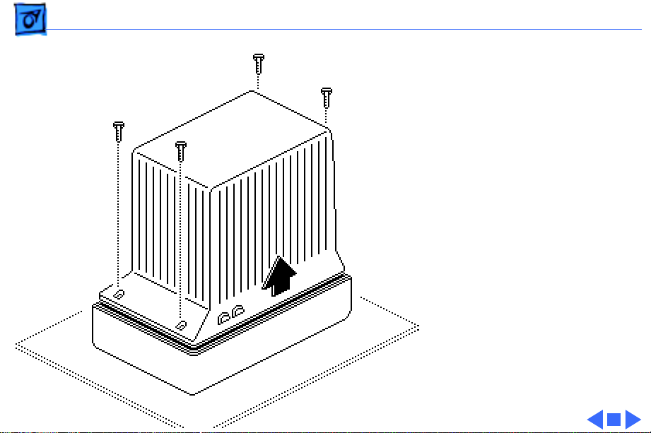
Take Apart CRT - 46
4 Remove the four
mounting screws from
the CRT.
5 Caution: The neck of the
CRT is easily damaged.
Do not grab the neck of
the CRT to remove it
from the bezel.
Carefully grasp and pull
the sides of the CRT from
the chassis.
Page 71

K
Service Source
Adjustments
Macintosh Portrait Display
Page 72

Adjustments Monitor Safety - 2
Monitor Safety
When adjusting this monitor, be sure to follow all CRT
safety instructions outlined in Bulletins/Safety. Make sure
you are familiar with these warnings and cautions:
Warning:
high-vacuum picture tube. To prevent serious injury,
review CRT safety in Bulletins/Safety.
Warning:
monitor. Position a mirror to view the screen. Do not reach
around the monitor to adjust the controls.
Caution
Switch off the monitor before connecting and disconnecting
the alligator clips to/from the test points.
The Portrait Display contains high voltage and a
Adjustments are made from the rear of the
: When measuring voltage, avoid a possible short.
Page 73

Adjustments Light Meter Setup - 3
Light Meter Setup
This topic covers setup for
three light meter models:
R77, L-248, and 246.
Model R77 (Apple part
number 076-0310) is the
newest model available.
Model R77
The R77 light meter is
capable of reading luminance
from 10 to 1,000
footcandles (fc).
Before you begin, remove
the 10X multiplier plate
Page 74

Adjustments Light Meter Setup - 4
from the lens.
Three scales are shown on
the light meter:
• 200-1000 fc
• 50-250 fc
• 10-50 fc
Because display screen
luminance typically ranges
from 10 to 50 fc, take
readings from the bottom
scale only.
Page 75

Adjustments Light Meter Setup - 5
To measure a display
screen’s luminance,
1 Set the scale switch to
the bottom position (to
set up the 10-50 fc
scale).
2 Place the lens against the
middle of the screen and
read the bottom scale.
Note:
When the light meter
is not in use, slide the scale
switch to its top position,
and store the meter in its
protective case.
Important:
light meter is giving false
If you suspect the
Page 76

Adjustments Light Meter Setup - 6
readings, verify the
readings with a known-good
light meter or photometer.
Also check the age of the R77
light meter by its four-digit
manufacturing date stamp
(such as 0398 for March
1998).
Caution:
meter can permanently
damage its accuracy. A
shock-damaged meter might
read incorrectly or its
pointer may not drop to
zero.
Dropping the
Page 77

Adjustments Light Meter Setup - 7
Side Switch
Scale
Lens
Read Button
Red Area
Model L-248
1 Press the red button on
the back of the light
meter. If the reading is
out of the red area,
replace the battery.
2 Move the side switch to
its upper position so that
the scale reads 10
through 18.
3 Uncover the lens of the
meter.
4 Place the lens against the
middle of the screen and
press the read button to
read the scale.
Page 78

Adjustments Light Meter Setup - 8
Model 246
1 Remove the metal slide,
Lens
if installed, from the
top of the light meter.
Swivel Head
Scale
2 Install the white lens
with the red dot.
3 Rotate the swivel head
so the lens of the meter
faces the monitor.
Place the lens against the
middle of the screen and read
the scale.
Page 79

Adjustments Geometry - 9
Geometry
Before you begin, remove
the rear cover.
Phase
V.Lin
H.F.
V.F.
Focus
H.Size
H.Cent
Height
V.Cent
Warning:
This product
contains high voltage and a
high-vacuum picture tube.
To prevent serious injury,
review CRT safety in
Bulletins/Safety.
Note:
Geometry adjustments
may be necessary whenever
you replace the power/
sweep board.
Page 80

Adjustments Geometry - 10
Horizontal Size
1 Use Display Service
Utility to display the
All-White Screen test
All-White
Screen
H.Size
pattern.
2 Using the plastic
screwdriver, adjust the
horizontal size (H.Size)
control until the raster
width is 8 inches (± 1/8
inch) or 203 mm (± 2
mm).
Page 81

Adjustments Geometry - 11
Horizontal Center
1 Using the plastic
screwdriver, adjust the
horizontal center
All-White
Screen
H.Cent
(H.Cent) control until
the raster is centered
(left to right) in the
display area.
2 Verify that the raster
width is 8 inches (± 1/8
inch) or 203 mm (± 2
mm) wide. If it is not,
repeat the horizontal
size and horizontal
center adjustments.
Page 82

Adjustments Geometry - 12
Horizontal Phase
1 Measure the black
margin on the right side
of the display. The black
All-White
Screen
H.Phase
margin should measure
1/4 inch or 7 to 8 mm
from the right edge of
the white raster to the
edge of the plastic bezel.
2 If necessary, use the
plastic screwdriver to
adjust the horizontal
phase (H.Phase) control
until the black margin is
1/4 inch or 7 to 8 mm
wide.
Page 83

Adjustments Geometry - 13
Height
Using a plastic screwdriver,
adjust the height control
All-White
Screen
Height
until the raster height is 10
7/8 inches (± 1/8 inch) or
276 mm (± 2 mm).
Page 84

Adjustments Geometry - 14
Vertical Center
1 Using the plastic
screwdriver, adjust the
vertical center (V.Cent)
All-White
Screen
V.Cent
control until the raster
is centered (top to
bottom) in the display
area.
2 Verify that the raster
height is 10 7/8 inches
(± 1/8 inch) or 276
mm (± 2 mm). If it is
not, repeat the height
and vertical center
adjustments.
Page 85

Adjustments Geometry - 15
Vertical Linearity
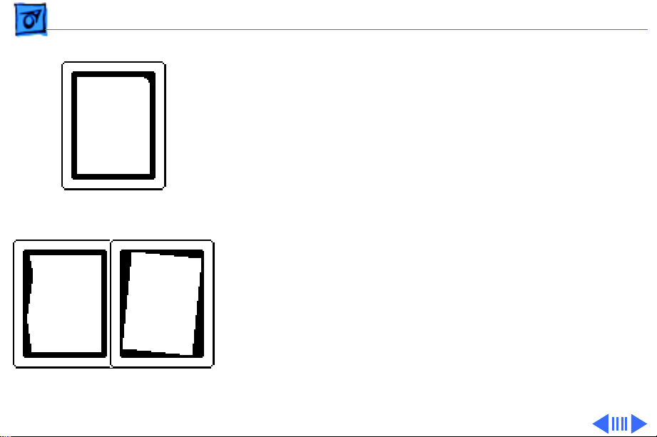
1 Use Display Service
Utility to display the
Crosshatch test pattern.
Crosshatch
V.Lin
2 Using a plastic
screwdriver, adjust the
vertical linearity
(V.Lin) control until
the boxes at the top of the
display are the same size
as those at the bottom.
Page 86

Adjustments Geometry - 16
Focus
Brightness
Contrast
Focus
1 Use Display Service
Utility to display the
Focus test pattern.
2 Set the external
contrast control to
maximum (turn fully
clockwise) and the
external brightness
control to the center
(detent) position.
Page 87

Adjustments Geometry - 17
3 Using a plastic
screwdriver, adjust the
focus controls as follows:
• Adjust the focus
control for the best
Focus
overall focus
• Adjust the H.F.
H.F.
control for the best
focus along the left
V.F.
and right edges of the
display
Focus
• Adjust the V.F. control
for the best focus at
the top and bottom
• Repeat the
adjustments until you
have attained the best
focus possible
Page 88

Adjustments Video With Screen Control - 18
Video With Screen Control
Before you begin, remove
Screen
Brightness
Contrast
GAIN
the following:
• Rear cover
• EMI shield
If the monitor doesn’t have a
screen control, go to “Video
Without Screen Control.”
SUB-
BRIGHT
Cutoff
Warning:
contains high voltage and a
high-vacuum picture tube.
To prevent serious injury,
review CRT safety in
Bulletins/Safety.
This product
Page 89

Adjustments Video With Screen Control - 19
Gray Bars
Caution:
To prevent
damaging the monitor,
reinstall the signal input
board with the two
mounting screws.
Note:
Perform the video
adjustments whenever the
CRT or video board has been
replaced or the display
appears to be maladjusted.
1 Switch on the monitor
and let it warm up for at
least 10 minutes.
2 Use Display Service
Utility to display the
Gray Bars test pattern.
Page 90

Adjustments Video With Screen Control - 20
3 Using a plastic
screwdriver, preset the
following controls:
• Screen control to
Gray Bars
maximum (turn fully
clockwise)
Screen
• GAIN control to its
midpoint
• SUB-BRIGHT control
to maximum (turn
fully clockwise)
GAIN
SUB-BRIGHT
Power Switch
Page 91

Adjustments Video With Screen Control - 21
Cutoff
1 Use Display Service
Utility to display the
All-Black Screen
Brightness
Contrast
All-Black Screen test
pattern.
2 Set the contrast control
and the brightness
control to maximum
(turn fully clockwise).
Page 92

Adjustments Video With Screen Control - 22
Note:
If you turn the cutoff
control up (clockwise) too
far, the monitor may shut
down. If this happens,
All-Black Screen
switch off the monitor, turn
the cutoff control all the way
down, and wait 30 seconds.
Then resume the adjustment.
3 Using the plastic
screwdriver, adjust the
cutoff control clockwise
until retrace lines are
just visible.
4 Then turn the cutoff
Cutoff
control counterclockwise until the retrace
lines just disappear.
Page 93

Adjustments Video With Screen Control - 23
Sub-Brightness
1 Use Display Service
Utility to display the
Gray Bars test pattern.
Gray Bars
2 Set the brightness
control to the center
(detent) position.
Brightness
SUB-BRIGHT
3 Set the SUB-BRIGHT
control so that the
leftmost bar is
completely black.
Page 94

Adjustments Video With Screen Control - 24
Screen Luminance
1 Use Display Service
Utility to display the
All-White Screen test
All-White Screen
pattern.
Important:
light meter models R77,
L-248, and 246 differ.
Please note which meter
you are using before making
adjustments. (See “Light
Meter Setup” in this
chapter.)
Readings from
Page 95

Adjustments Video With Screen Control - 25
2 Measure screen
luminance with the light
meter. You should get
40 foot lamberts (± 3
All-White Screen
foot lamberts), which on
the light meter is
• Model R77: 29 on the
bottom scale
• Model L-248: 10 to
11 on the 10–18 scale
• Model 246: 29 on the
red scale
Important:
Over time, light
meter tolerances can vary.
If in doubt, verify the
readings with a known-good
light meter or photometer.
Page 96

Adjustments Video With Screen Control - 26
3 Set the brightness
control to the center
position, and recheck the
screen luminance. The
All-White Screen
reading should not go
beyond 60 fL, which on
the light meter is
• Model R77: 40 on the
bottom scale
Brightness
• Model L-248: 11 to
12 on the 10–18 scale
GAIN
• Model 246: 40 on the
red scale
4 If necessary, repeat the
SUB-BRIGHT
SUB-BRIGHT and GAIN
adjustments until you
obtain a correct reading.
Page 97

Adjustments Video Without Screen Control - 27
Video Without Screen Control
Before you begin, remove
the following:
• Rear cover
Brightness
Contrast
GAIN
BIAS
SUB-
BRIGHT
TP1
TP2
Cutoff
• EMI shield
Warning:
contains high voltage and a
high-vacuum picture tube.
To prevent serious injury,
review CRT safety in
Bulletins/Safety.
This product
Page 98

Adjustments Video Without Screen Control - 28
Caution:
damaging the monitor,
reinstall the signal input
board with the two
mounting screws.
Note:
adjustments whenever the
CRT or video board has been
replaced or the display
appears to be maladjusted.
To prevent
Perform the video
Page 99

Adjustments Video Without Screen Control - 29
Bias
1 Switch on the monitor
and let it warm up for at
least 10 minutes.
All-Black Screen
Brightness
Contrast
SUB-BRIGHT
Power Switch
2 Preset the SUB-BRIGHT
control to minimum
(fully counterclockwise).
3 Use Display Service
Utility to display the
All-Black Screen.
4 Set the brightness
control and contrast
control to minimum
(turn fully counterclockwise).
Page 100

Adjustments Video Without Screen Control - 30
Note:
For accurate voltage
measurements, use two
shielded alligator clip leads
and a high quality DC
voltmeter.
TP1
TP2
Power Switch
Caution
: To avoid a short,
switch off the monitor
before connecting the
alligator clips.
5 Switch off the monitor.
6 Connect one end of a
shielded alligator clip
lead to TP1 on the CRT
board. Connect the
other end to the positive
probe of a DC voltmeter.
 Loading...