

Page 1
Service Source
Power Mac G4 (Mirrored Drive Doors)
Power Mac G4 (FW 800)
Updated 22 February 2006
© 2003 Apple Computer, Inc. All rights reserved.
Page 2

Service Source
Take Apart
Power Mac G4 (Mirrored Drive Doors)
Power Mac G4 (FW 800)
© 2003 Apple Computer, Inc. All rights reserved.
Page 3
General Information
Overview
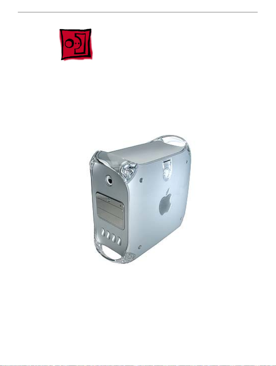
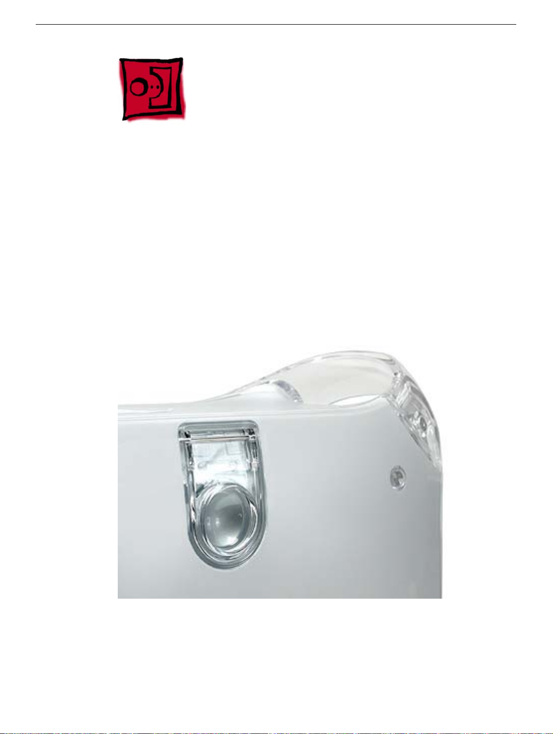
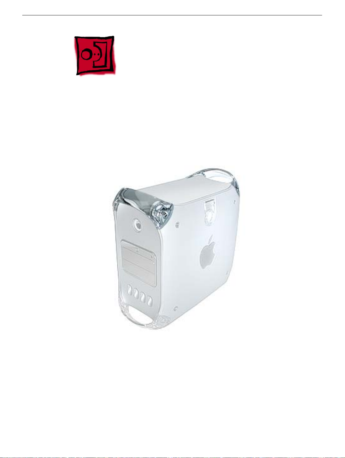
The identifying characteristics on the front of the Power Mac G4 (Mirrored Drive Doors),
Power Mac G4 (Mirrored Drive Doors 2003), and Power Mac G4 (FW 800) computers are
their top speaker and mirrored optical drive bezel. Like the Power Mac G4 (QuickSilver
and QuickSilver 2002) computers, these models also have a silver-colored case.
The Power Mac G4 (Mirrored Drive Doors 2003) computer is identical to the Power Mac
G4 (Mirrored Drive Doors) computer except for updates to the drives and processor.
The Power Mac G4 (FW 800) computer is similar to the Power Mac G4 (Mirrored Drive
Doors) computer with these exceptions:
• FireWire 800 Mbps port
• AirPort Extreme Card option
• Bluetooth option
• SCSI card option is a third-party card; no Apple SCSI card option
• SCSI cable is a third-party cable; no Apple SCSI cable
General Information
Power Mac G4 (Mirror/FW 800) Take Apart -
1
Page 4

Important:
unless model differences are noted.
The Take Apart procedures are the same for all versions of the computers
Tools
The following tools are required:
• #2 Phillips screwdriver
• #1 Phillips screwdriver
• T-10 Torx driver or 2.5 mm Allen wrench
• Small flat-blade screwdriver
• Needlenose pliers
Note:
Magnetized tools are recommended to avoid dropping screws within the computer.
Note:
To organize the screws you remove from the computer, use a tray with divided
compartments (such as a plastic ice cube tray).
Serial Number Location
The computer’s serial number is located on the back panel.
Before Opening the Computer
Warning:
be opened for any reason, even when the computer is off.
Warning:
it to allow internal components to cool.
Important:
disconnect their power plugs from the power source. Make sure the power cords to the
computer and display are within easy reach.
Electrostatic Discharge (ESD) Precautions
Follow these steps to avoid damage from ESD before working inside the computer.
1. Shut down the computer.
2. Wait a few minutes to allow the computer’s internal components to cool.
3. Unplug all cables from the computer except the power cord.
4. Touch the metal PCI access covers on the back panel to discharge static electricity.
5. Unplug the power cord.
The power supply in this computer is a high-voltage component and should not
After shutting down the computer, you must wait a few minutes before servicing
The only way to shut off power completely to the computer and display is to
6. Lift the latch on the side of the computer. (If the latch will not lift, check that the
security lock port and lockable cover latch in the back of the computer are not locked.)
2 -
Power Mac G4 (Mirror/FW 800) Take Apart
General Information
Page 5

7. Put on an ESD wrist strap.
8. To avoid static electricity building back up in your body, do not walk around the room
until after you have finished working and closed the computer.
Operating the Computer
Warning: In this computer the lower fan is in direct line with the heatsink. However,
when the computer is open and the side panel is set down, the fan and heatsink are
no longer in contact. To avoid overheating and permanent damage, never turn on
the computer unless all of its internal and external parts are in place and it is
closed. Operating the computer when it is open or missing parts can damage the
computer or cause injury.
General Information
Power Mac G4 (Mirror/FW 800) Take Apart -
3
Page 6
Opening the Computer
Tools
No tools are required for this procedure.
Preliminary Steps
No preliminary steps are required before you begin this procedure.
Procedure
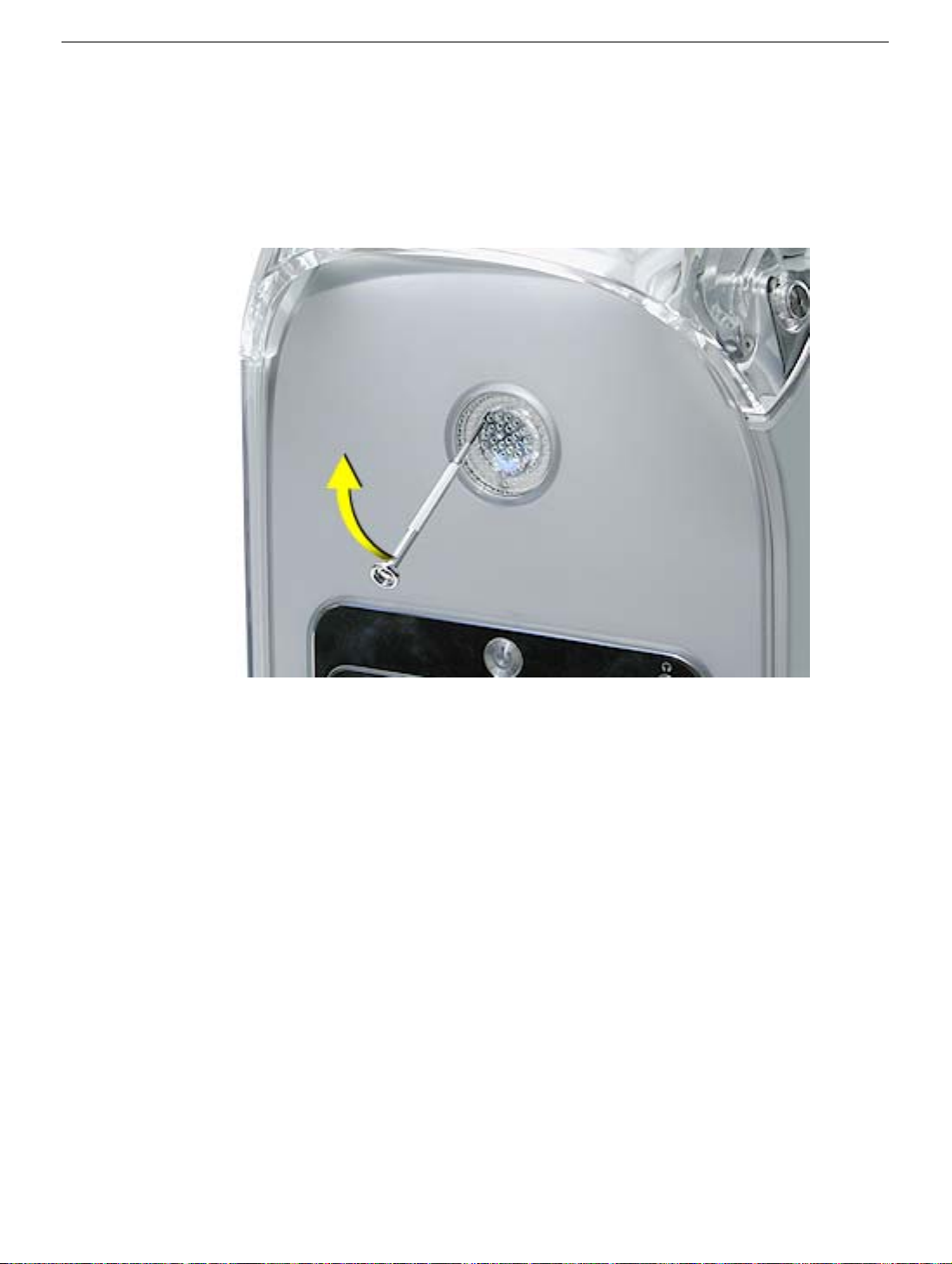
1. Lift the latch to unlock the right side access panel.
2.
Note:
Gently lower the side panel onto a clean, ESD-safe mat to avoid scratching the
case. Lower the side panel until it lies flat.
Note:
Release the latch before returning the side panel to its upright closed position.
4 -
Power Mac G4 (Mirror/FW 800) Take Apart
Opening the Computer
Page 7
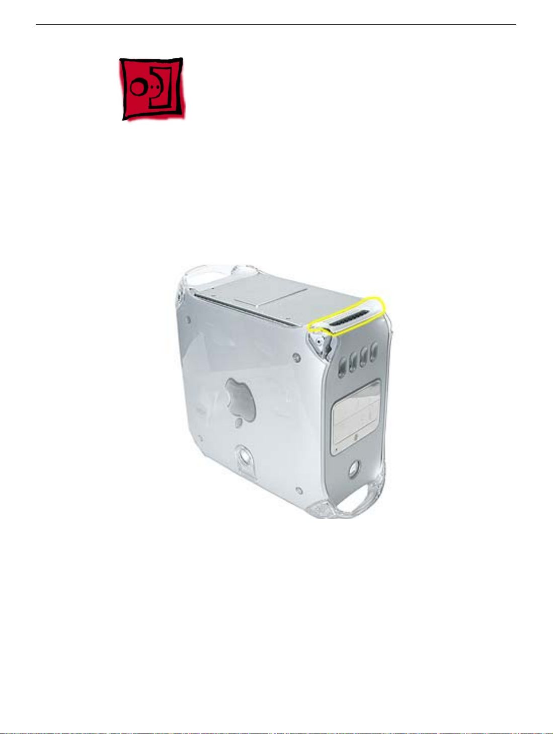
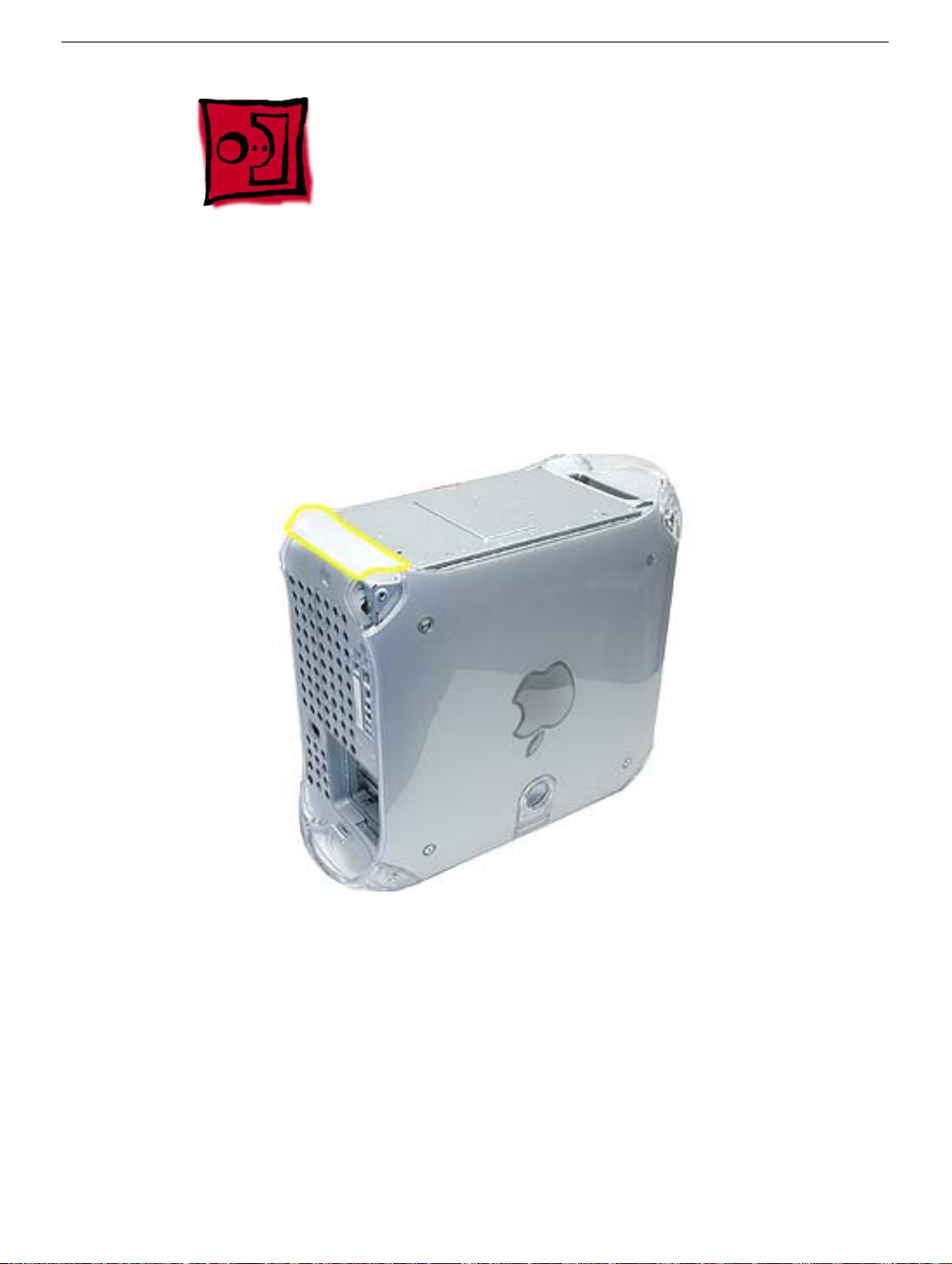
Top Handles
Tools
The only tool required for this procedure is a 2.5 mm Allen wrench.
Part Location
Top Handles
Preliminary Steps
There are no preliminary steps for this procedure.
Power Mac G4 (Mirror/FW 800) Take Apart -
5
Page 8
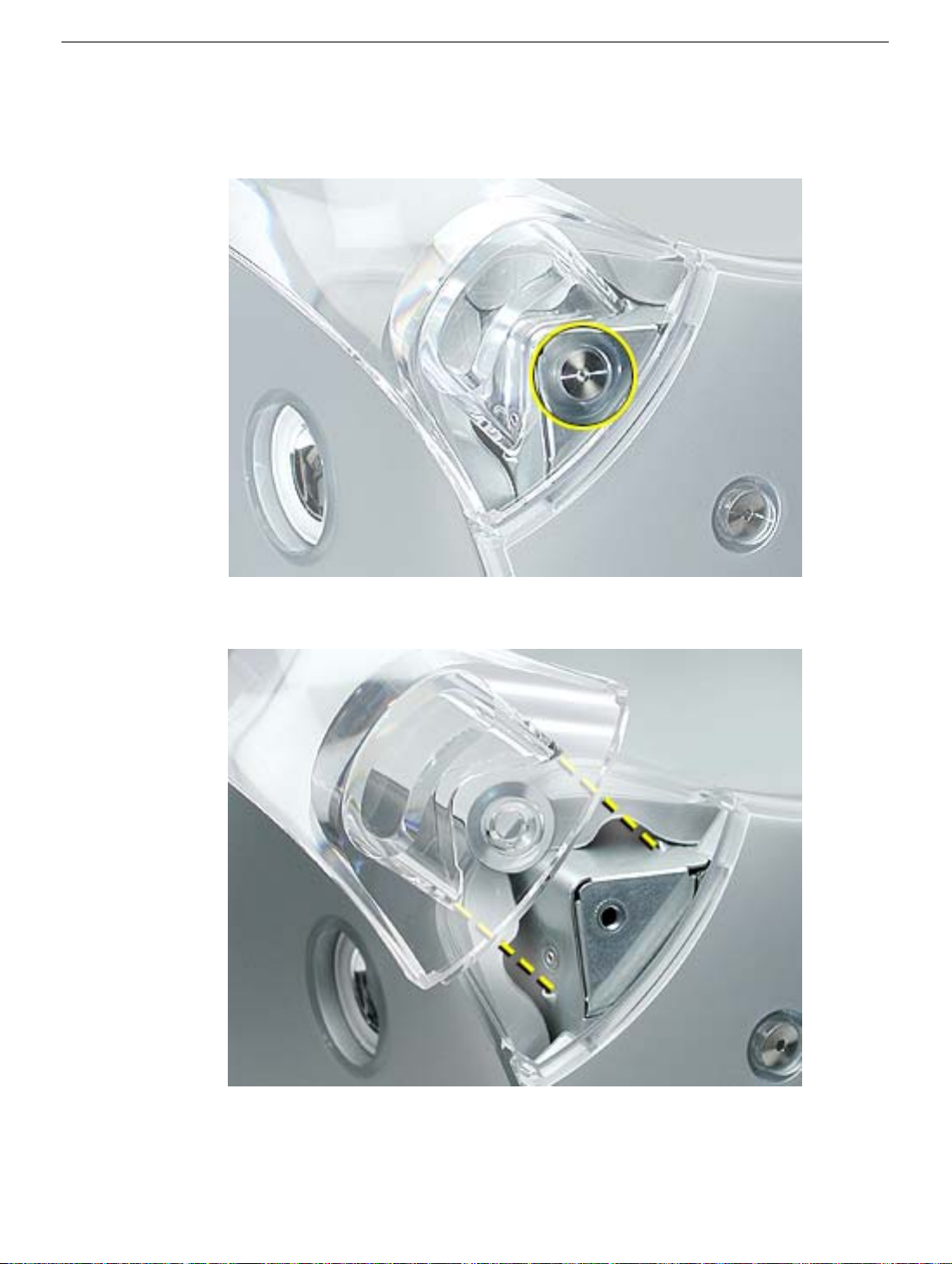
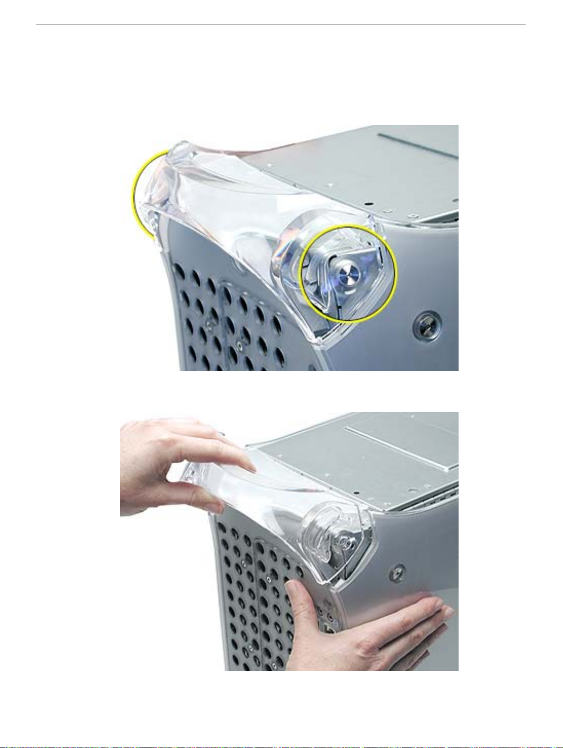
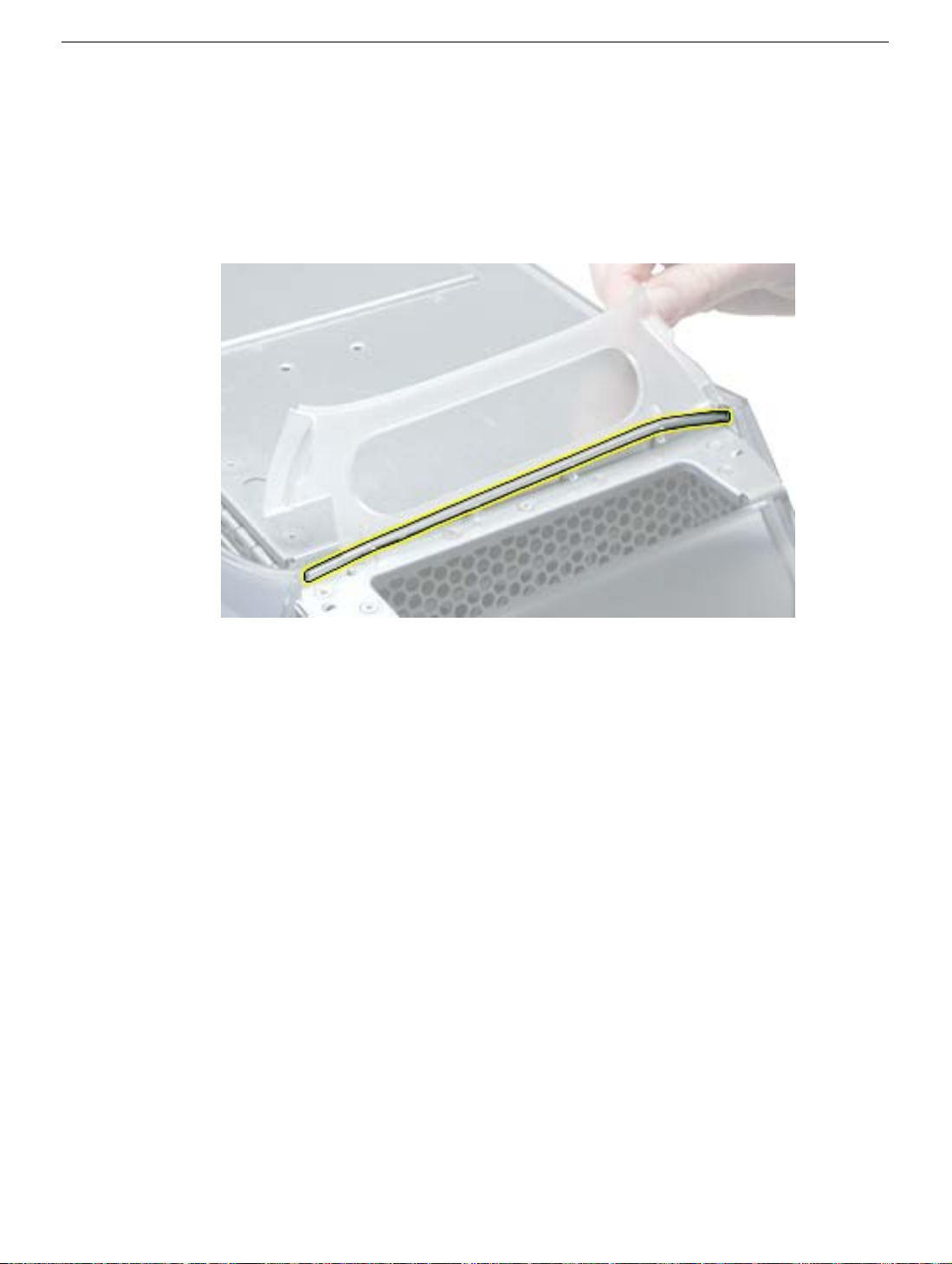
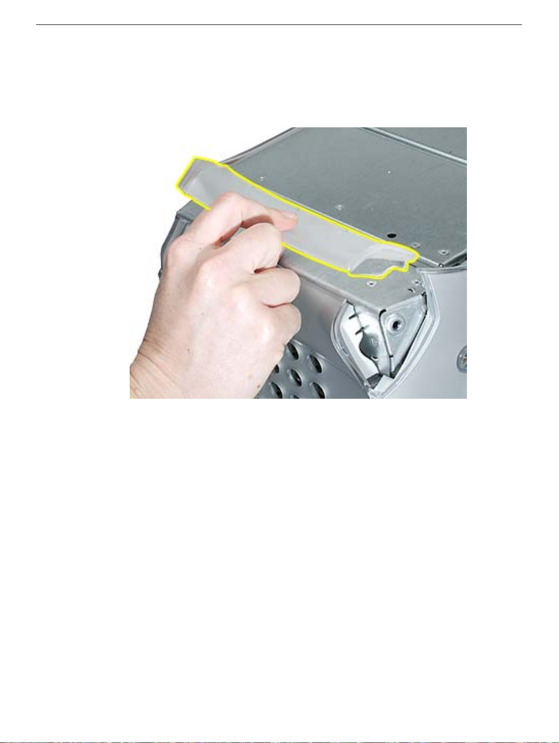
Procedure
1. Remove the two Allen screws that secure the handle you are replacing.
2. Lift the handle from the computer.
Replacement Note:
raised points on the computer.
6 -
Power Mac G4 (Mirror/FW 800) Take Apart
When replacing a handle, make sure the inner prongs fit inside the
Top Handles
Page 9
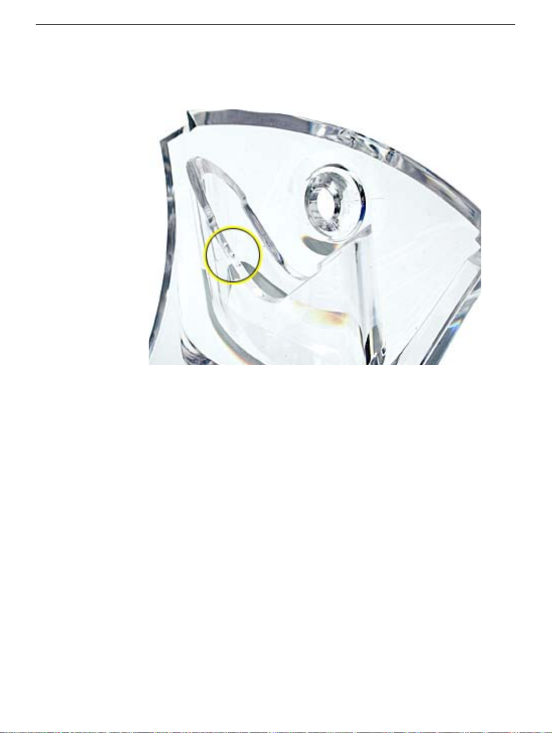
Replacement Note:
three tiny bumps are near the lower edge of the handle.The handle won’t fit properly if it is
turned upside down. The top front and top rear handles are interchangeable.
When replacing a handle, make sure you orient the handle so the
Top Handles
Power Mac G4 (Mirror/FW 800) Take Apart -
7
Page 10
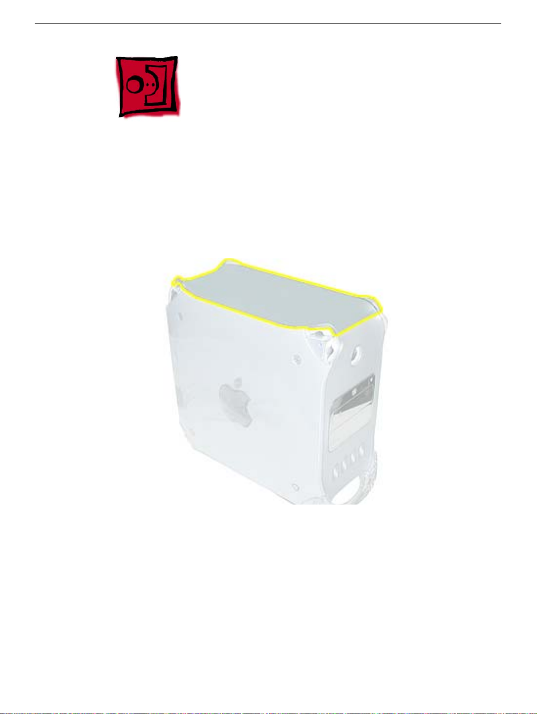
Top Panel
Tools
No tools are required for this procedure.
Part Location
Preliminary Steps
Before you begin, remove the handles from the top front and top rear of the
computer.
8 -
Power Mac G4 (Mirror/FW 800) Take Apart
Top Panel
Page 11
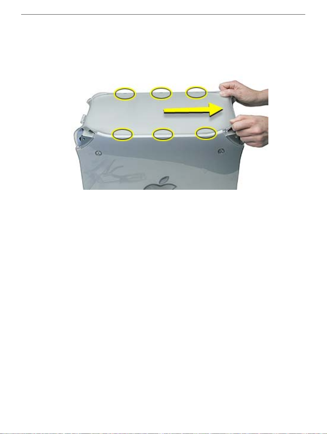
Procedure
1. Slide the top panel toward the front of the computer to unhook the six tabs.
2. Lift the top panel from the chassis.
Top Panel
Power Mac G4 (Mirror/FW 800) Take Apart -
9
Page 12
Speaker Grill
Tools
The only tool required for this procedure is a small flat-blade screwdriver.
Part Location
Preliminary Steps
There are no preliminary steps for this procedure.
10 -
Power Mac G4 (Mirror/FW 800) Take Apart
Speaker Grill
Page 13
Procedure
1. Insert the tip of a screwdriver into one of the openings in the speaker grill.
Warning:
2. Pry out the speaker grill.
To prevent damage to the speaker, do not insert the screwdriver too far.
Replacement Note:
Press the replacement speaker grill into the speaker opening.
Speaker Grill
Power Mac G4 (Mirror/FW 800) Take Apart -
11
Page 14
Lower Supports
Tools
The only tool required for this procedure is a 2.5 mm Allen wrench.
Part Location
Preliminary Steps
Before you begin, place the computer upside down on an ESD mat.
Warning:
computer can be unstable.
12 -
Power Mac G4 (Mirror/FW 800) Take Apart
When the computer is upside down or the lower supports are removed, the
Lower Supports
Page 15
Procedure
1. With the computer upside down, remove the two Allen screws securing the support to
the computer.
2. Remove the support from the computer.
Lower Supports
Power Mac G4 (Mirror/FW 800) Take Apart -
13
Page 16
Lower Panel, Front
Tools
No tools are required for this procedure.
Part Location
Preliminary Steps
Before you begin, remove the lower front support.
Warning:
computer can be unstable.
14 -
Power Mac G4 (Mirror/FW 800) Take Apart
When the computer is upside down or the lower support is removed, the
Lower Panel, Front
Page 17
Procedure
1. Lift the lower front panel from the chassis. There are no screws holding this panel to
the chassis; the front support holds it in place.
2.
Important:
from the notches in the lower front panel.
Note the routing of the AirPort antenna cable. Carefully remove it
Lower Panel, Front
Power Mac G4 (Mirror/FW 800) Take Apart -
15
Page 18
Lower Panel, Rear
Tools
No tools are required for this procedure.
Part Location
Preliminary Steps
Before you begin, remove the lower rear support.
Warning:
computer can be unstable.
16 -
Power Mac G4 (Mirror/FW 800) Take Apart
When the computer is upside down or the lower support is removed, the
Lower Panel, Rear
Page 19
Procedure
Lift the lower rear panel from the chassis. There are no screws holding this panel to the
chassis; the rear support holds it in place.
Lower Panel, Rear
Power Mac G4 (Mirror/FW 800) Take Apart -
17
Page 20
Rear Vented Panel
Tools
The following tools are required for this procedure:
• 2.5 mm Allen wrench
• Flat-blade screwdriver
Part Location
Preliminary Steps
Before you begin, remove the following:
• Lower rear support
• Lower rear panel
• Top rear handle
Warning:
computer can be unstable.
18 -
Power Mac G4 (Mirror/FW 800) Take Apart
When the computer is upside down or the lower supports are removed, the
Rear Vented Panel
Page 21
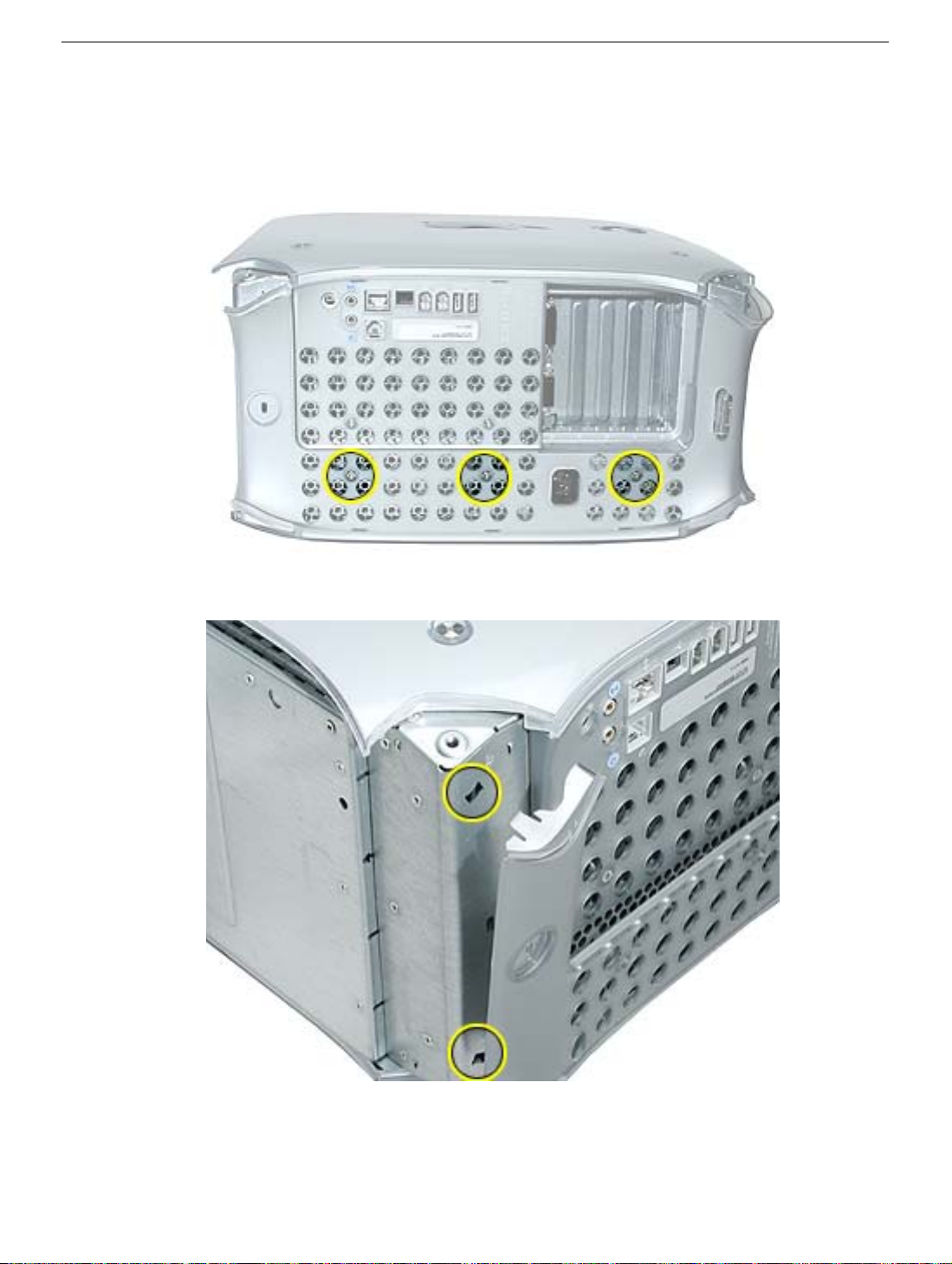
Procedure
1. With the computer positioned on its left side panel, remove the three Allen screws
securing the rear vented panel to the computer.
2. Use a flat-blade screwdriver to pry out the tabs from the lower chassis.
Rear Vented Panel
Power Mac G4 (Mirror/FW 800) Take Apart -
19
Page 22
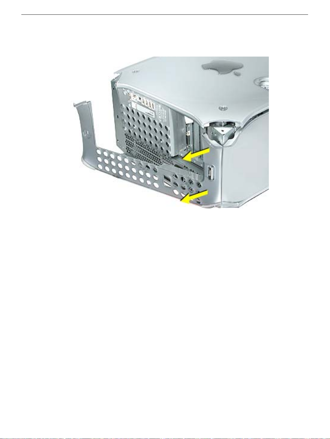
3. Grasp the rear vented panel on both sides of the lockable cover latch, and forcefully
pull off the rear vented panel.
20 -
Power Mac G4 (Mirror/FW 800) Take Apart
Rear Vented Panel
Page 23
Hard Drive Carrier, Back
Tools
The following tools are required for this procedure:
• Magnetized #2 Phillips screwdriver.
• Pliers
Part Location
Preliminary Steps
Before you begin, open the side access panel.
Hard Drive Carrier, Back
Power Mac G4 (Mirror/FW 800) Take Apart -
21
Page 24
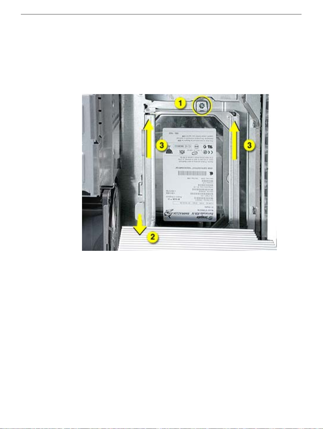
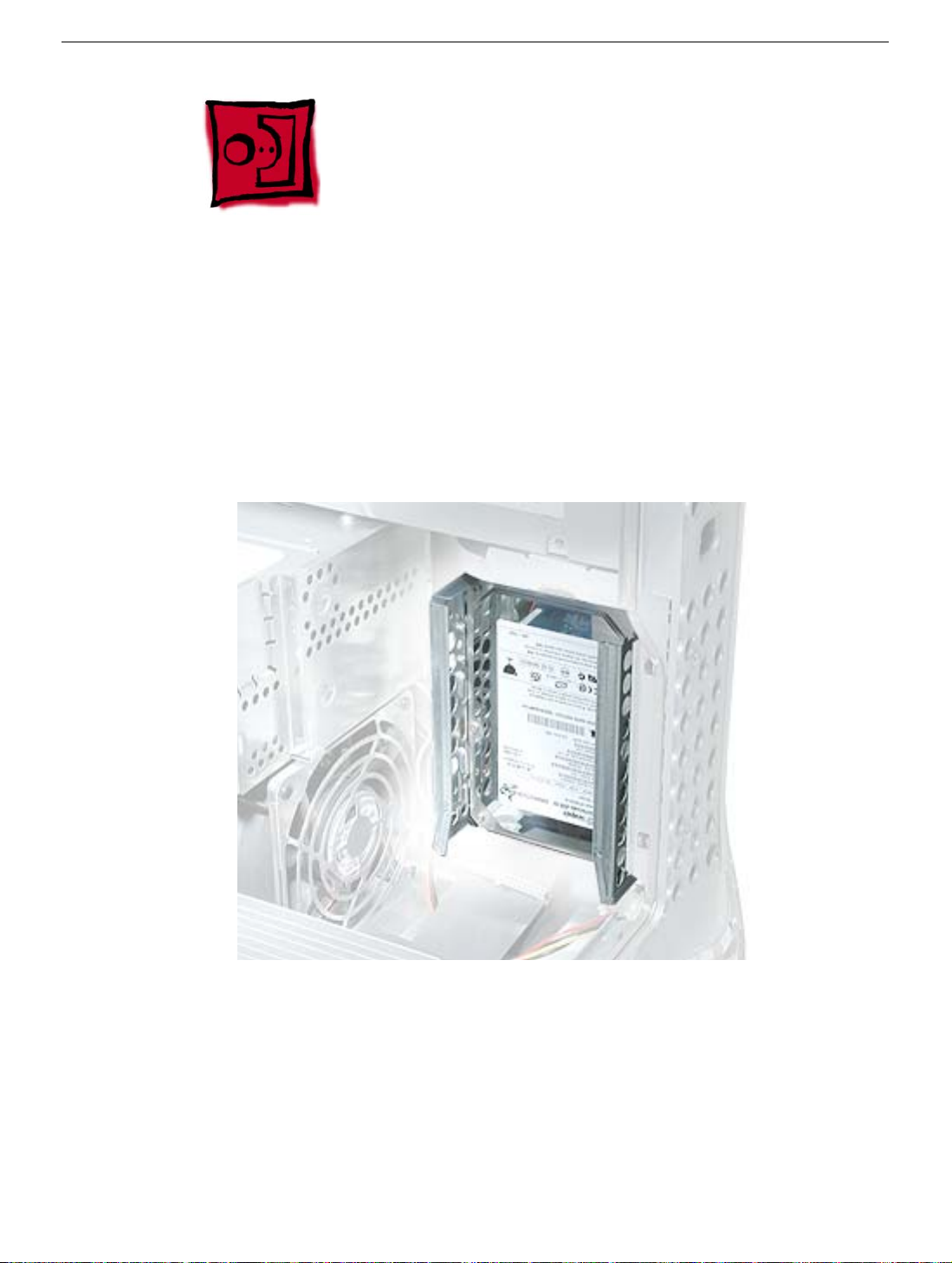
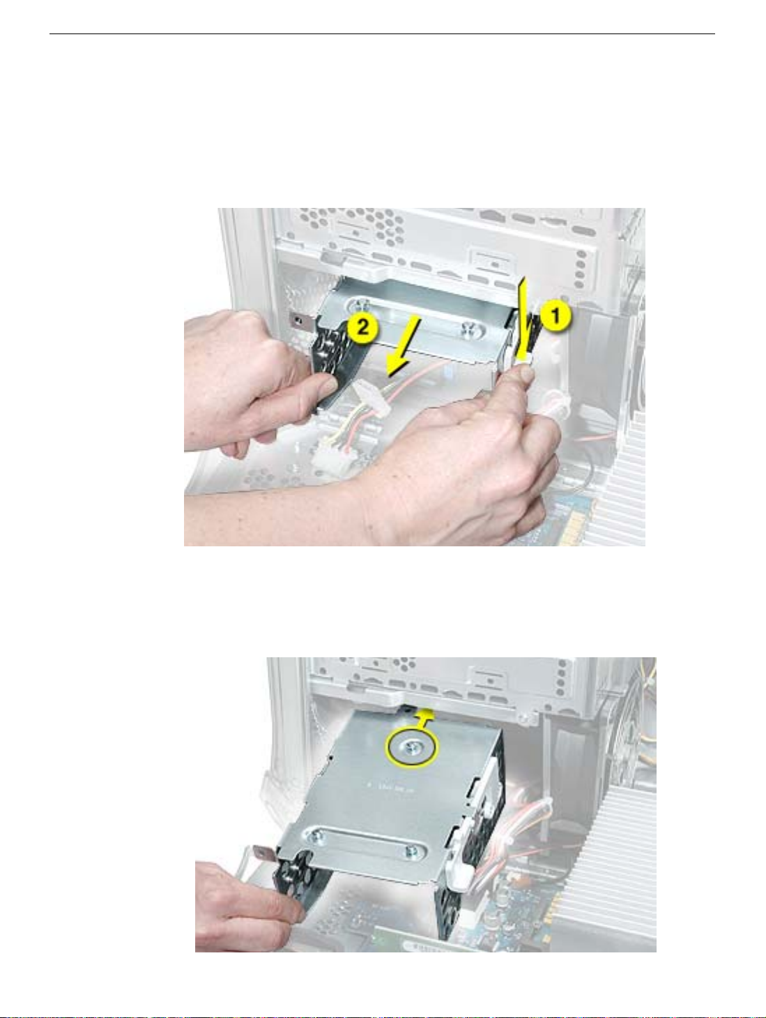
Procedure
1. Using a Phillips screwdriver, remove the screw that attaches the carrier to the chassis.
Note:
On some production models, the screw is not present nor required.
2. Pull the left side lever forward, and slide the carrier up to release the mounting pegs
on the back of the carrier from the chassis.
22 -
Power Mac G4 (Mirror/FW 800) Take Apart
Hard Drive Carrier, Back
Page 25
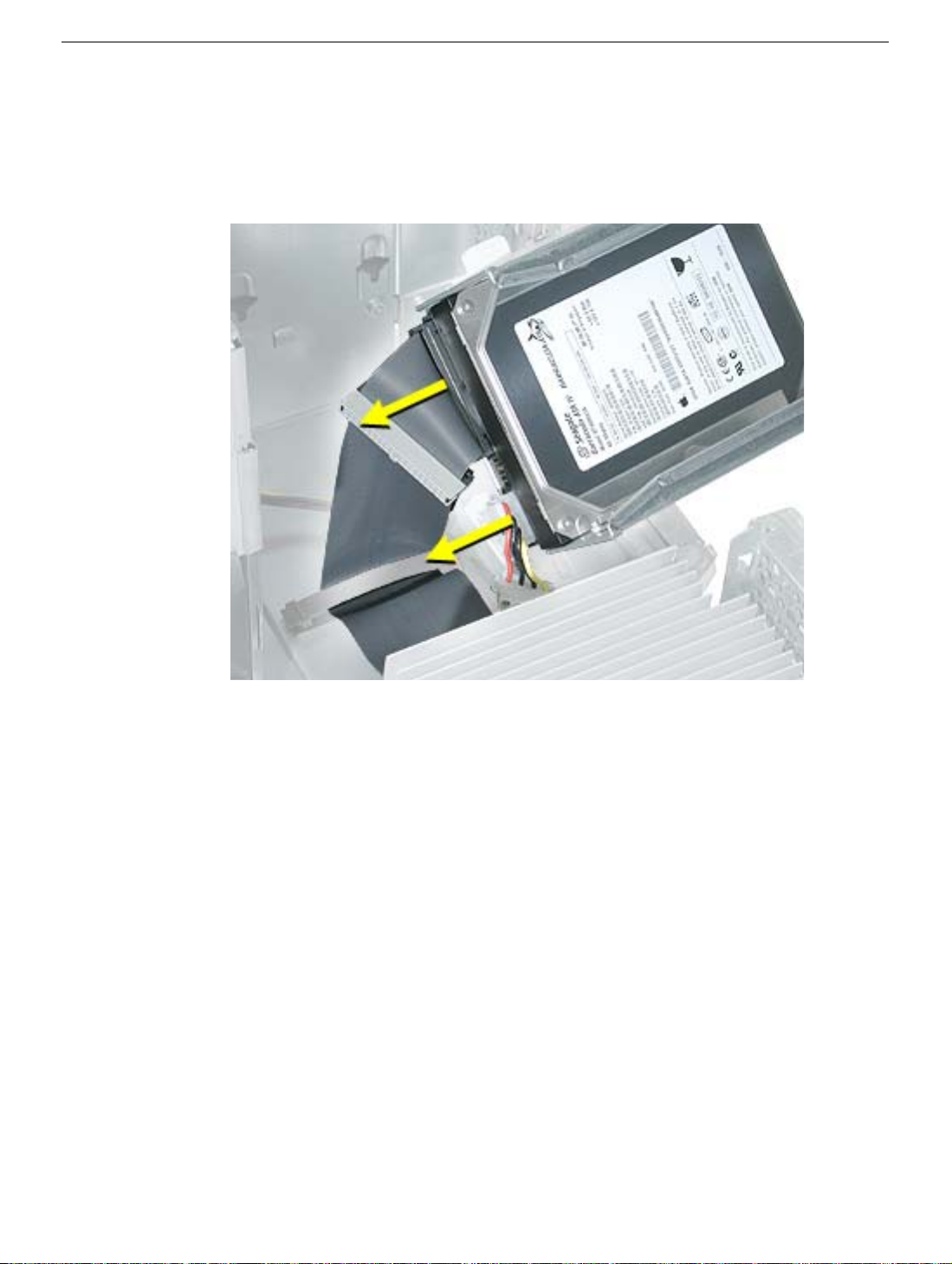
3. Rotate the carrier back from the chassis far enough to reach the drive cables.
Disconnect the hard drive data and power cables (P2 and P3) from the hard drive(s).
Note: You might need to use pliers to grasp and disconnect the power cable
connector(s).
4. Remove the carrier and drive(s) from the computer.
Replacement Note: Connect the cables to the drives before installing the carrier.
Hard Drive Carrier, Back
Power Mac G4 (Mirror/FW 800) Take Apart -
23
Page 26
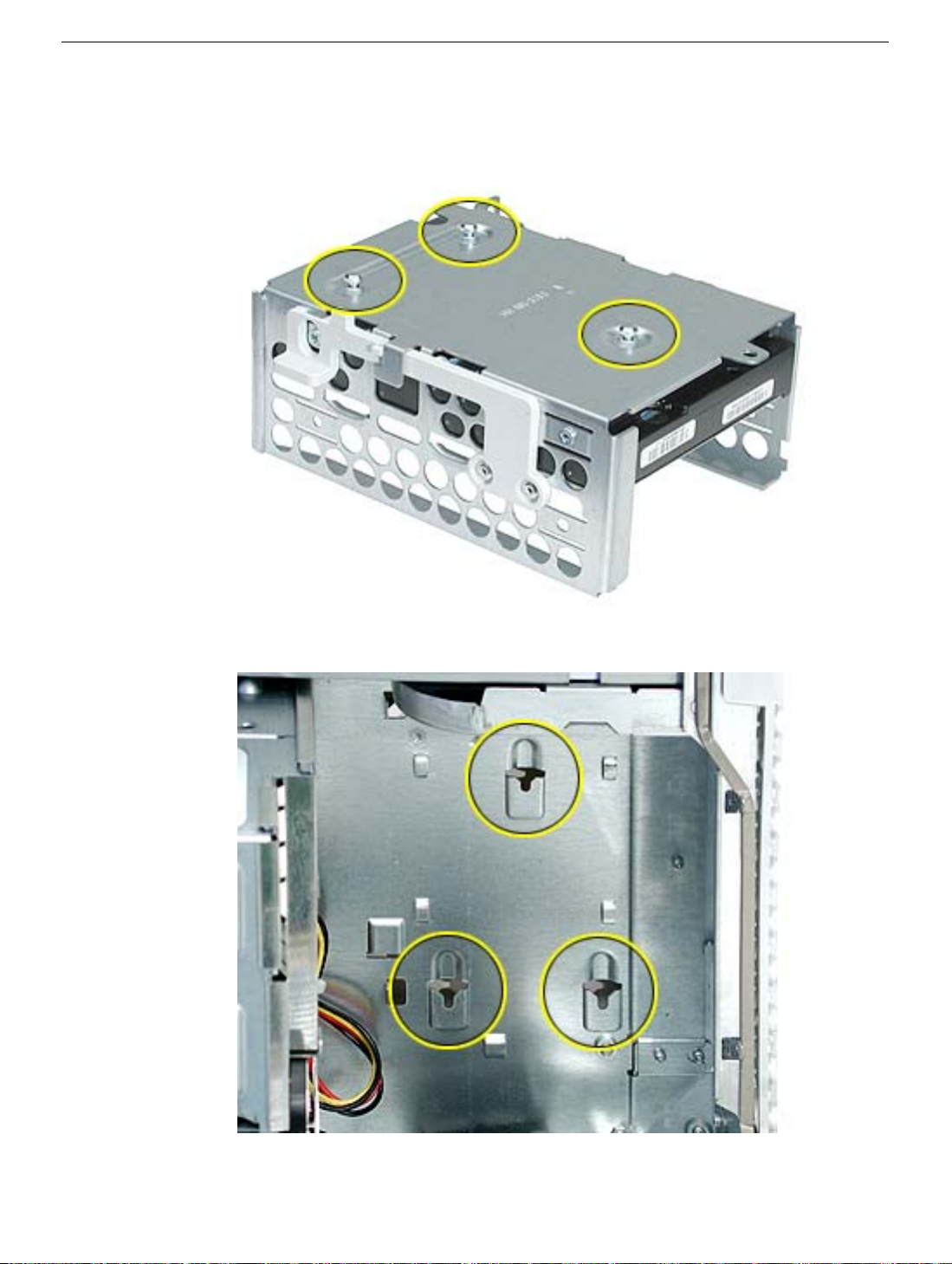
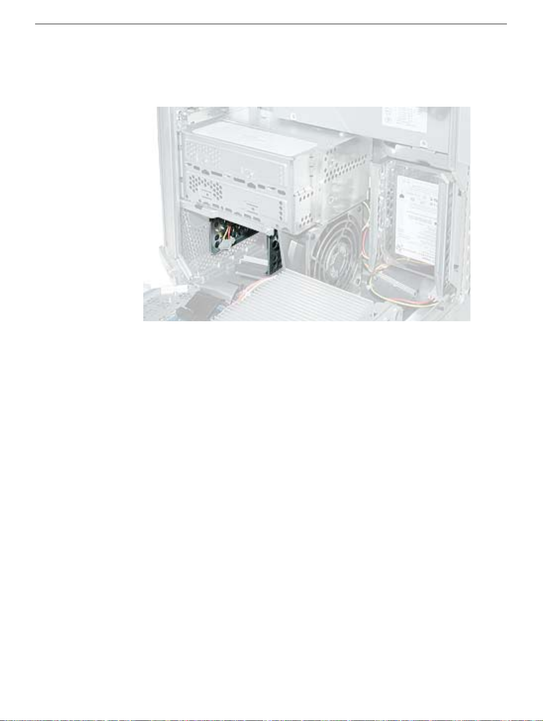
Replacement Note: Be sure to align the mounting pegs on the back of the carrier with the
notches in the chassis. Then press the carrier in and down until the pegs engage and the
left side lever clicks into place.
24 - Power Mac G4 (Mirror/FW 800) Take Apart
Hard Drive Carrier, Back
Page 27
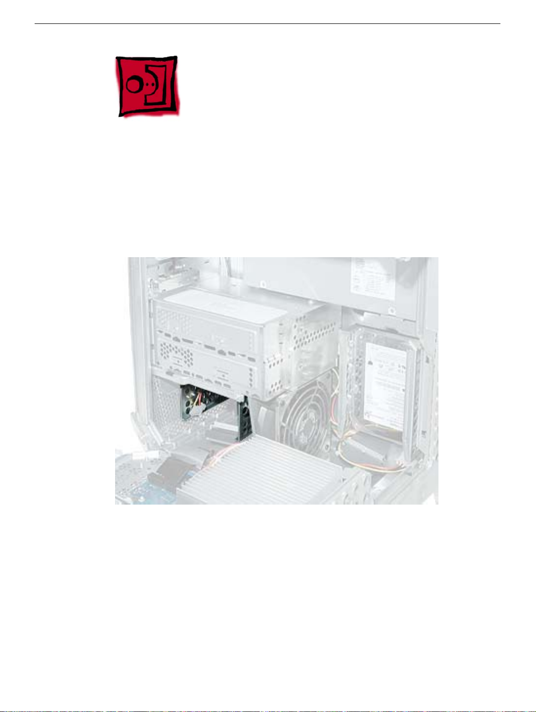
Hard Drive Carrier, Front
Tools
The only tool required for this procedure is a magnetized Phillips screwdriver.
Part Location
Preliminary Steps
Before you begin, open the side access panel.
Hard Drive Carrier, Front
Power Mac G4 (Mirror/FW 800) Take Apart - 25
Page 28
Procedure
1. Press down on the carrier’s right side lever.
2. Holding the lever down, slide the carrier forward and out of the computer.
Warning: Be careful not to scrape any cables when sliding the carrier forward.
Replacement Note: Align the center mounting peg on the top of the carrier with the
center channel on the underside of the optical drive shelf. This center peg helps to guide
the carrier. Then align the two remaining pegs, and slide the carrier in until the pegs
engage and the right side lever clicks into place.
26 - Power Mac G4 (Mirror/FW 800) Take Apart
Hard Drive Carrier, Front
Page 29
Replacement Note: Before closing the side access panel, make sure the P4 and P5
power cable connectors are either attached to the hard drives or tucked inside the front
hard drive carrier.
Hard Drive Carrier, Front
Power Mac G4 (Mirror/FW 800) Take Apart - 27
Page 30
Hard Drive
Tools
The only tool required for this procedure is a Phillips screwdriver.
Preliminary Steps
Before you begin, do the following:
• Open the side access panel.
• Remove the hard drive carrier.
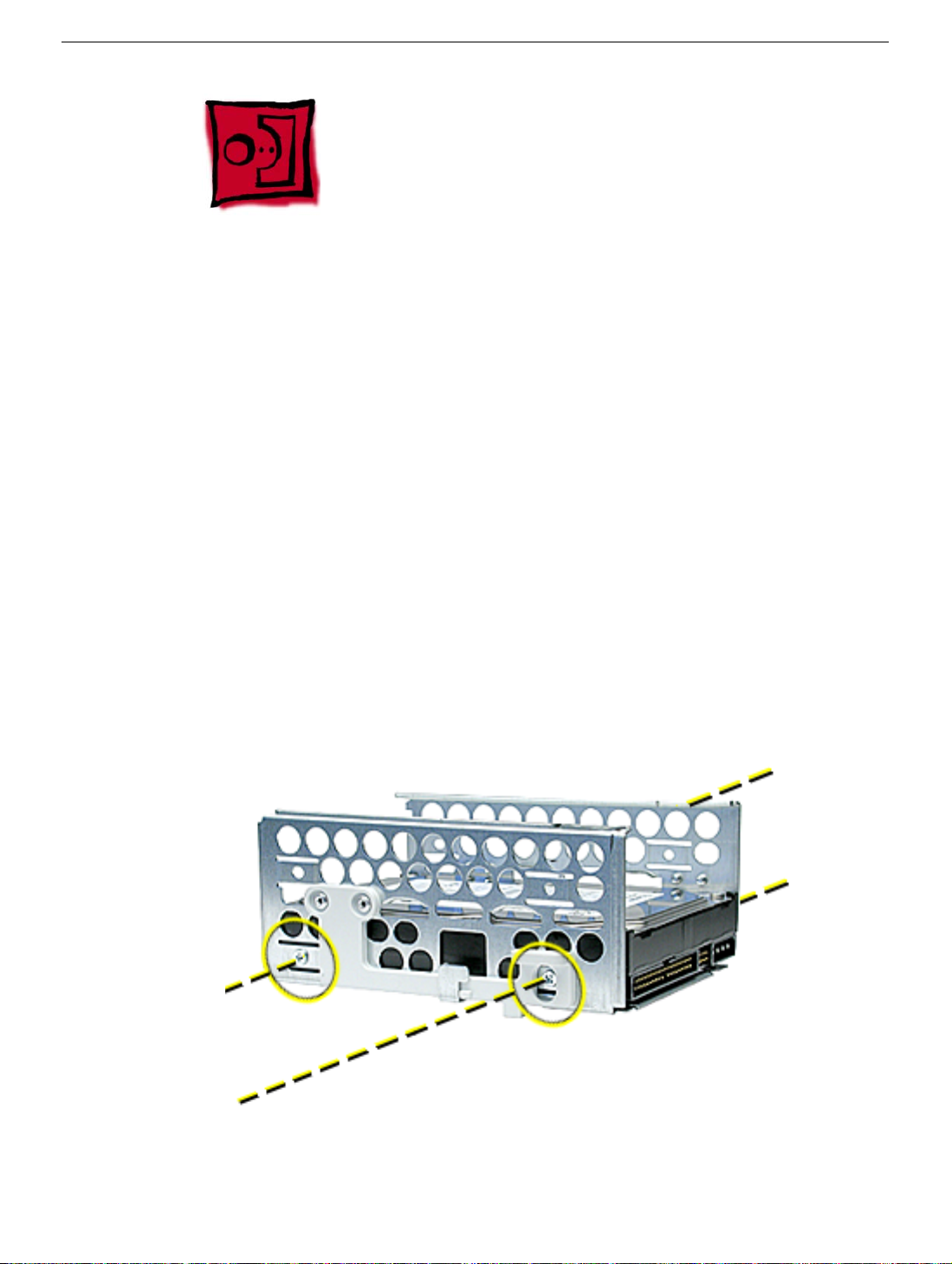
Procedure
1. Remove the four mounting screws from the sides of the drive carrier.
2. Slide the drive forward out the front of the drive carrier.
28 - Power Mac G4 (Mirror/FW 800) Take Apart
Page 31

ATA 100 Hard Drive Cable
Tools
No tools are required for this procedure.
Preliminary Steps
Before you begin, do the following:
• Open the side access panel.
• Remove the back hard drive carrier.
Procedure
1. Open the cable clamp at the bottom of the chassis.
2. Disconnect the ATA 100 cable from the connector at J34 on the logic board.
Power Mac G4 (Mirror/FW 800) Take Apart - 29
Page 32

Optical Drive
Tools
The only tool required for this procedure is a Phillips screwdriver.
Part Location
Preliminary Steps
Before you begin, open the side access panel.
30 - Power Mac G4 (Mirror/FW 800) Take Apart
Optical Drive
Page 33

Procedure
1. Loosen the captive screw near the front panel board.
2. Remove the lower screw that secures the optical drive carrier to the chassis.
3. Slide the back panel off the carrier.
Optical Drive
Power Mac G4 (Mirror/FW 800) Take Apart - 31
Page 34

4. Slide the carrier back and rotate it so that you can reach the drive cables.
5. Disconnect the drive data and power cables (P6 and P7) from the back of the optical
drive(s) and remove the carrier from the computer.
6. Remove the four mounting screws from the sides of the drive carrier.
7. Slide the drive forward out the front of the drive carrier.
32 - Power Mac G4 (Mirror/FW 800) Take Apart
Optical Drive
Page 35

Replacement Note: Before sliding the carrier back onto the optical drive shelf, make sure
the power cable bundle at the side panel is routed in the recessed channel.
Optical Drive
Power Mac G4 (Mirror/FW 800) Take Apart - 33
Page 36

Replacement Note: When sliding the carrier back onto the optical drive shelf, make sure
the latch on the underside of the carrier engages with the notch in the drive shelf.
Replacement Note: Before sliding the rear panel back onto the carrier, make sure the top
lip of the panel engages with the top edge of the drive carrier.
Warning: Be careful not to pinch the power cable between the panel and the carrier.
34 - Power Mac G4 (Mirror/FW 800) Take Apart
Optical Drive
Page 37

Optical Drive Cable
Tools
No tools are required for this procedure.
Preliminary Steps
Before you begin, do the following:
• Open the side access panel.
• Remove the front hard drive carrier.
• Remove the optical drive carrier.
Procedure
1. Peel up the optical drive cable from the double-sided tape on the optical drive shelf.
Power Mac G4 (Mirror/FW 800) Take Apart - 35
Page 38

2. Open the two cable clamps at the bottom of the chassis.
3. Disconnect the cable from the logic board and free the cable from the opening in the
optical drive shelf.
36 - Power Mac G4 (Mirror/FW 800) Take Apart
Optical Drive Cable
Page 39

Lower Fan
Tools
The only tool required for this procedure is a small flat-blade screwdriver.
Part Location
Preliminary Steps
Before you begin, do the following:
• Open the side access panel.
• Remove the optical drive carrier.
Power Mac G4 (Mirror/FW 800) Take Apart - 37
Page 40

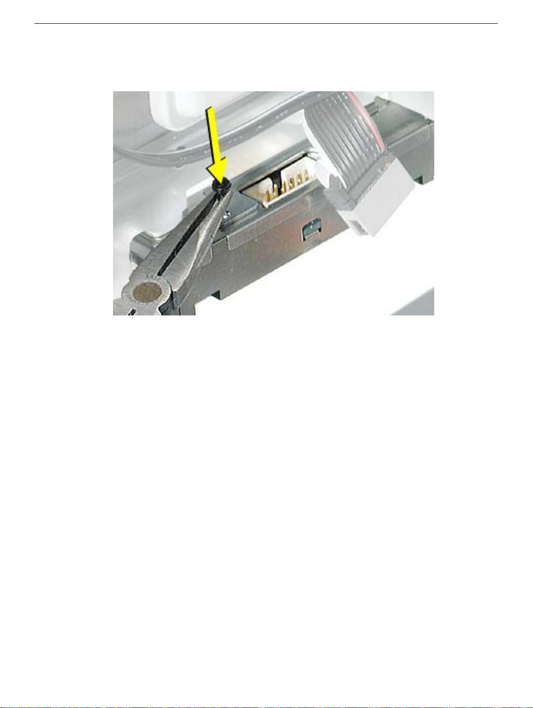
Procedure
1. Disconnect the ribbon cable from the logic board and fold it back to expose the lower
fan cable connector.
2. Using a small flat-blade screwdriver, gently lift up the locking tab on the lower fan
cable and disconnect the cable from the logic board.
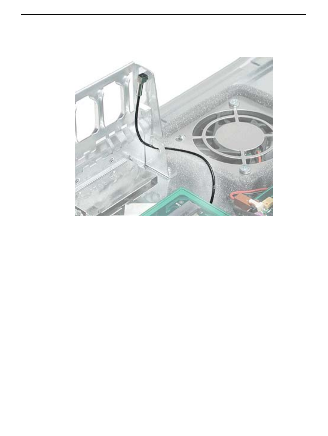
Replacement Note: Route the fan cable under the ribbon cable and over the narrower flex
cable, as shown.
38 - Power Mac G4 (Mirror/FW 800) Take Apart
Lower Fan
Page 41

3. Slide the fan straight up to disconnect it from the optical drive shelf, and remove the
fan from the computer.
Replacement Note: Align the fan with the three latches in the drive shelf and slide straight
down until you feel the fan lock into place.
Lower Fan
Power Mac G4 (Mirror/FW 800) Take Apart - 39
Page 42

Replacement Note: On some production models, the fan includes a detachable finger
guard. To transfer the finger guard to the replacement fan, use a needlenose pliers to
remove the four plastic pegs. Then transfer the finger guard to the replacement fan.
40 - Power Mac G4 (Mirror/FW 800) Take Apart
Lower Fan
Page 43
Left Side Panel
Tools
The following tools are required for this procedure:
• 2.5 mm Allen wrench
• Needlenose pliers
Part Location
Left Side Panel
Preliminary Steps
Before you begin, open the computer and remove the optical drive carrier.
Power Mac G4 (Mirror/FW 800) Take Apart - 41
Page 44

Procedure
1. Remove the four 2.5 mm Allen screws on the side panel.
2. Using a needlenose pliers, squeeze the tabs (located beside the power supply
cable bundle) to release the left side panel from the metal chassis.
3. Lift the left side panel from the chassis.
42 - Power Mac G4 (Mirror/FW 800) Take Apart
Left Side Panel
Page 45

Front Panel
Tools
No tools are required for this procedure.
Part Location
Front Panel
Before you begin, open the computer and remove the following.
• Handle at the top front of the computer
• Support at the lower front of the computer
• Speaker grill (if present)
• Optical drive carrier
Warning: When the lower support is removed, the computer can be unstable.
Power Mac G4 (Mirror/FW 800) Take Apart - 43
Page 46

Procedure
1. Open the side access panel. Locate the four front panel tabs.
2. Carefully push the front panel tabs inward to release them from the chassis.
3. Pull the front panel off the chassis.
4. Press inward on the four tabs to remove the optical drive bezel from the front panel.
44 - Power Mac G4 (Mirror/FW 800) Take Apart
Front Panel
Page 47

Power Supply
Tools
The following tools are required for this procedure:
• #2 Phillips screwdriver
• T-10 Torx driver
Part Location
Preliminary Steps
Before you begin, do the following:
• Open the side access panel.
• Remove the optical drive carrier.
• Remove the lower fan.
Power Mac G4 (Mirror/FW 800) Take Apart - 45
Page 48

Procedure
Warning: The power supply in this computer is a high-voltage component and should not
be opened for any reason, even when the computer is off.
1. Use a T-10 Torx driver to remove the power supply screw from the back panel.
2. Remove the Phillips screw from the side panel.
46 - Power Mac G4 (Mirror/FW 800) Take Apart
Power Supply
Page 49

3. Disconnect the power supply cables from all drives and from the logic board.
Note: For the Power Mac G4 (FW 800) model of the computer, press and hold the
tab on the black, plastic connector cover as you pull up the power connector from the
board.
Replacement Note: Install the connector cover over the power connector for the
replacement power supply.
4. Release the power cable harness from the guides and route the harness out through
the opening in the optical drive shelf.
Power Supply
Power Mac G4 (Mirror/FW 800) Take Apart - 47
Page 50

5. Slide the power supply forward and remove the power supply and cable harness from
the computer.
Replacement Note: When rerouting the cable harness, make sure
• connectors P4 and P5 are routed inside the front drive carrier
• connectors P2 and P3 are routed so they can reach drives in the back drive carrier
48 - Power Mac G4 (Mirror/FW 800) Take Apart
Power Supply
Page 51

Speaker
Tools
The following tools are required for this procedure:
• #2 Phillips screwdriver.
• Small flat-blade screwdriver
Part Location
Preliminary Steps
Before you begin, do the following:
• Open the side access panel.
• Remove the optical drive carrier.
Power Mac G4 (Mirror/FW 800) Take Apart - 49
Page 52

Procedure
1. Using a small flat-blade screwdriver, lift up the locking tab on the speaker cable
connector and disconnect the cable from the logic board.
2. Remove the cable from the cable guide.
3. Route the cable up and out through the opening in the optical drive shelf and out from
under the speaker case.
50 - Power Mac G4 (Mirror/FW 800) Take Apart
Speaker
Page 53

4. Remove the speaker mounting screw.
5. Swing the speaker away from the chassis. Press in on the two latches on the right side
of the speaker and release the speaker from the chassis.
Speaker
Power Mac G4 (Mirror/FW 800) Take Apart - 51
Page 54

6. Remove the speaker and cable from the computer.
Replacement Note: With the replacement speaker attached to the chassis, make sure to
route the speaker cable through the chassis guides, as shown.
52 - Power Mac G4 (Mirror/FW 800) Take Apart
Speaker
Page 55

Optical Drive Bezel
Tools
No tools are required for this procedure.
Part Location
Optical Drive Bezel
Preliminary Steps
Before you begin, do the following:
• Open the side access panel.
• Remove the optical drive carrier.
Power Mac G4 (Mirror/FW 800) Take Apart - 53
Page 56

Procedure
1. Press in and release the top two latches on the inside of the optical drive bezel.
2. Press in and release the bottom two latches.
3. Remove the bezel from the computer.
54 - Power Mac G4 (Mirror/FW 800) Take Apart
Optical Drive Bezel
Page 57

Front Panel Board
Tools
The following tools are required for this procedure:
• #2 Phillips screwdriver
• Small flat-blade screwdriver
• Needlenose pliers
Part Location
Front Panel Board
Preliminary Steps
Before you begin, do the following:
• Open the side access panel.
• Remove the optical drive carrier.
• Remove the optical drive bezel.
Power Mac G4 (Mirror/FW 800) Take Apart - 55
Page 58

Procedure
1. Disconnect the front panel board cable from the front panel board.
2. Using a small flat-blade screwdriver, pry up the two black plastic pegs and then the
two black plastic peg holders from the top of the front panel board.
3. Using a #2 Phillips screwdriver, remove the front panel board mounting screw.
4. Remove the front panel board through the front opening in the computer.
56 - Power Mac G4 (Mirror/FW 800) Take Apart
Front Panel Board
Page 59
Replacement Note: When replacing the black plastic peg holders, use needlenose pliers
to compress the holders so they will fit into the holes in the top of the front panel board.
Front Panel Board
Power Mac G4 (Mirror/FW 800) Take Apart - 57
Page 60

Front Panel Board Cable
Tools
No tools are required for this procedure.
Part Location
Preliminary Steps
Before you begin, do the following:
• Open the side access panel.
• Remove the front hard drive carrier.
• Remove the optical drive carrier.
• Loosen the speaker cable.
58 - Power Mac G4 (Mirror/FW 800) Take Apart
Page 61

Procedure
1. Disconnect the front panel board cable from the front panel board.
2. Peel the front panel board cable from the recessed channel in the side chassis and
route the cable through the opening in the optical drive shelf.
Front Panel Board Cable
Power Mac G4 (Mirror/FW 800) Take Apart - 59
Page 62

3. Open the two cable clamps at the bottom of the chassis and disconnect the front panel
board connector from the logic board.
60 - Power Mac G4 (Mirror/FW 800) Take Apart
Front Panel Board Cable
Page 63

Optical Fan
Tools
The following tools are required for this procedure:
• #2 Phillips screwdriver
• Small flat-blade screwdriver
Part Location
Preliminary Steps
Before you begin, open the side access panel.
Power Mac G4 (Mirror/FW 800) Take Apart - 61
Page 64

Procedure
1. Using a small flat-blade screwdriver, gently lift up the locking tab on the optical fan
cable and disconnect the cable from the logic board.
2. Remove the two Phillips screws from the fan baffle.
62 - Power Mac G4 (Mirror/FW 800) Take Apart
Optical Fan
Page 65

3. Slide the fan baffle forward to clear the two pegs, and lift the fan baffle off of the fan.
4. Pull the fan straight up to remove it from the two pegs. Route the fan cable under the
surrounding foam wall.
Replacement Note: If the foam wall is damaged, replace it by peeling off the old foam
and cleaning the chassis surface with an alcohol wipe. Then apply the new foam wall to
the chassis.
Optical Fan
Power Mac G4 (Mirror/FW 800) Take Apart - 63
Page 66

DIMMs
Tools
No tools are required for this procedure.
Part Location
Preliminary Steps
Before you begin, do the following:
• Open the side access panel.
• Remove the heatsink if the DIMM is in the slot nearest the heatsink. (Note: The DIMM
nearest the heatsink can be removed with the heatsink in place; however the fit is
tight.)
64 - Power Mac G4 (Mirror/FW 800) Take Apart
DIMMs
Page 67

Procedure
1. Push down the ejectors on the DIMM slot.
2. Holding the DIMM by both top corners, lift it straight up out of the slot.
Warning: When removing or installing the DIMM, handle it only by the edges. Do not
touch its connectors. Lift the DIMM straight up from the connector to remove it, and insert
it straight down into the connector to install it. Do not rock the DIMM from side to side.
DIMMs
Replacement Note: The DIMM is designed to fit into the slot only one way. Be sure to
align the notch in the DIMM with the small rib inside the slot.
Power Mac G4 (Mirror/FW 800) Take Apart - 65
Page 68

Modem
Tools
The only tool required for this procedure is a Phillips screwdriver.
Part Location
Preliminary Steps
Before you begin, open the side access panel.
66 - Power Mac G4 (Mirror/FW 800) Take Apart
Modem
Page 69

Procedure
1. Using a Phillips screwdriver, remove the modem’s two mounting screws.
2. Lift the modem straight up a short distance to disconnect it from the logic board.
3. Disconnect the modem cable from the modem.
4. Remove the modem from the computer.
Modem
Power Mac G4 (Mirror/FW 800) Take Apart - 67
Page 70

AirPort Card
Note: This section applies to the Power Mac G4 (MIrrored Drive Doors) computer only. If
you are replacing an AirPort Extreme Card—the smaller card—go to the next section.
Tools
No tools are required for this procedure.
Part Location
Preliminary Steps
Before you begin, open the side access panel.
68 - Power Mac G4 (Mirror/FW 800) Take Apart
AirPort Card
Page 71

Procedure
1. Detach the coaxial antenna wire from the port on the end of the AirPort Card.
2. Pull the clear plastic tab on the AirPort Card to disconnect the card from the connector
on the logic board.
AirPort Card
Power Mac G4 (Mirror/FW 800) Take Apart - 69
Page 72

Note: If you are not replacing the AirPort Card, stow the antenna wire on the side of the
PCI card guide, being careful not to bend or crimp the wire tightly.
Warning: Handle the AirPort antenna with care. Due to the cable routing through the
chassis panels, an AirPort antenna can be replaced only by ordering a new computer
enclosure.
70 - Power Mac G4 (Mirror/FW 800) Take Apart
AirPort Card
Page 73

AirPort Extreme Card
Note: This section applies to the Power Mac G4 (FW 800) computer only. If you are
replacing the original AirPort Card— the larger card—go to the previous section.
Tools
No tools are required for this procedure.
Part Location
Preliminary Steps
Before you begin, open the side access panel.
AirPort Extreme Card
Power Mac G4 (Mirror/FW 800) Take Apart - 71
Page 74

Procedure
1. Detach the coaxial antenna wire from the port on the end of the AirPort Extreme Card.
2. Pull the clear plastic tab on the card to disconnect the card from the connector on the
logic board.
72 - Power Mac G4 (Mirror/FW 800) Take Apart
AirPort Extreme Card
Page 75
Note: If you are not replacing the AirPort Extreme Card, stow the antenna wire on the side
of the card guide, being careful not to bend or crimp the wire tightly.
Warning: Handle the AirPort antenna with care. Due to the cable routing through the
chassis panels, an AirPort antenna can be replaced only by ordering a new computer
enclosure.
AirPort Extreme Card
Power Mac G4 (Mirror/FW 800) Take Apart - 73
Page 76

Bluetooth
Note: This section applies to the Power Mac G4 (FW 800) computer only.
Tools
No tools are required for this procedure.
Part Location
Preliminary Steps
Before you begin, open the side access panel.
74 - Power Mac G4 (Mirror/FW 800) Take Apart
Bluetooth
Page 77

Procedure
1. Holding the edges of the bluetooth board, pull the board straight up to disconnect it
from the logic board.
2. Turn over the board and pull the round connector off the board.
Bluetooth
Power Mac G4 (Mirror/FW 800) Take Apart - 75
Page 78

Note: If you are not replacing Bluetooth, stow the antenna wire on the side of the PCI card
guide, being careful not to bend or crimp the wire tightly.
76 - Power Mac G4 (Mirror/FW 800) Take Apart
Bluetooth
Page 79

Video Card
Tools
The only tool required for this procedure is a Phillips screwdriver.
Part Location
Video Card
Preliminary Steps
Before you begin, open the side access panel.
Power Mac G4 (Mirror/FW 800) Take Apart - 77
Page 80

Procedure
1. Using a Phillips screwdriver, remove the video card mounting screw.
2. Gently hold back the clip on the video card connector to release the card.
3. Pull the card straight up, and remove it from the computer.
78 - Power Mac G4 (Mirror/FW 800) Take Apart
Video Card
Page 81

Replacement Note: Install an AGP card in slot 1 only. Install PCI cards in the slots
labeled PCI 2, 3, 4, and 5.
Warning: Cables with large connectors may interfere with the enclosure in the PCI slot
numbered 5, making it difficult to close the door and potentially causing damage to the PCI
card. If this is the case, rearrange the cards in the slots. You may also connect the cable
after the enclosure door is shut, but be sure to remove the cable before opening the door
again. If the PCI cards are connected to each other with cables or jumpers, take care
when closing the door.
Video Card
Power Mac G4 (Mirror/FW 800) Take Apart - 79
Page 82

SCSI Card
Note: This section applies to the Power Mac G4 (MIrrored Drive Doors) computer only. For
the Power Mac G4 (FW 800) computer, the SCSI card is offered only as a third-party
option, so refer to the third-party vendor for replacement of the card.
Tools
The only tool required for this procedure is a Phillips screwdriver.
Part Location
Preliminary Steps
Before you begin, open the side access panel.
80 - Power Mac G4 (Mirror/FW 800) Take Apart
SCSI Card
Page 83

Procedure
1. Disconnect the SCSI cable from the SCSI card.
2. Remove the SCSI card mounting screw.
SCSI Card
Power Mac G4 (Mirror/FW 800) Take Apart - 81
Page 84

3. Lift up the SCSI card from the slot on the logic board.
82 - Power Mac G4 (Mirror/FW 800) Take Apart
SCSI Card
Page 85

SCSI Cable
Note: This section applies to the Power Mac G4 (MIrrored Drive Doors) computer only. For
the Power Mac G4 (FW 800) computer, the SCSI cable is offered only as a third-party
option, so refer to the third-party vendor for replacement of the cable.
Tools
The only tool required for this procedure is a Phillips screwdriver.
Part Location
SCSI Cable
Preliminary Steps
Before you begin, open the side access panel.
Power Mac G4 (Mirror/FW 800) Take Apart - 83
Page 86

Procedure
1. Disconnect the SCSI cable from the SCSI card.
2. Disconnect the SCSI cable from the hard drives at the front and back hard drive
carriers.
3. Disconnect the SCSI cable from the SCSI terminator at the bottom of the chassis.
84 - Power Mac G4 (Mirror/FW 800) Take Apart
SCSI Cable
Page 87

Battery
Tools
No tools are required for this procedure.
Part Location
Battery
Preliminary Steps
Before you begin, do the following:
• Open the side access panel.
• Remove the video card if a full-length video card extends over the battery.
Power Mac G4 (Mirror/FW 800) Take Apart - 85
Page 88

Procedure
1. Note the orientation of the battery’s positive (+) end.
2. Remove the battery from its holder.
Note: You may first need to spread the two tabs on the holder slightly apart to
release the battery.
Note: When replacing the battery, make sure the positive (+) end of the battery aligns with
the + symbol on the battery holder.
86 - Power Mac G4 (Mirror/FW 800) Take Apart
Battery
Page 89

Heatsink
Note: This procedure is the same for both of the Power Mac G4 models, except for the
heatsink appearance and screws.
Tools
The following tools are required for this procedure:
• #1 Phillips screwdriver
• #2 Phillips screwdriver
Part Location
Heatsink
Preliminary Steps
Before you begin, open the side access panel.
Power Mac G4 (Mirror/FW 800) Take Apart - 87
Page 90

Procedure
1. Remove the heatsink mounting screws:
Power Mac G4 (Mirrored Drive Doors):
• small #1 Phillips screw at back panel shield
• medium #2 Phillips screws at heatsink bracket
• three large #2 Phillips screws at remaining corners of heatsink
88 - Power Mac G4 (Mirror/FW 800) Take Apart
Heatsink
Page 91

Power Mac G4 (FW 800):
• four 11-mm long #2 Phillips screws at heatsink
Power Mac G4 (FW 800), Best Configuration:
• four 11-mm long #2 Phillips screws at heatsink
Heatsink
Power Mac G4 (Mirror/FW 800) Take Apart - 89
Page 92

2. Lift the heatsink straight up and remove it from the computer.
Power Mac G4 (FW 800), Best Configuration:
Warning: Handle the heatsink with care. Do not touch the underside of the heatsink.
The solder joints at the heatsink coils are delicate and might be warm.
90 - Power Mac G4 (Mirror/FW 800) Take Apart
Heatsink
Page 93

Note: Whenever you remove the heatsink, you must clean the heatsink base and add new
thermal grease to the chips on the processor, as follows:
• Use a clean pad to carefully remove the existing thermal grease from both chips.
• Apply a 3-mm round dot of thermal grease on the center of both chips.
• Use an alcohol pad to gently clean and dry the underside of the heatsink.
• Ensure the heatsink is level as you CAREFULLY place it on the processor.
• Install the screws, loosely tightening each half way before fully tightening each screw.
Heatsink
Power Mac G4 (Mirror/FW 800) Take Apart - 91
Page 94
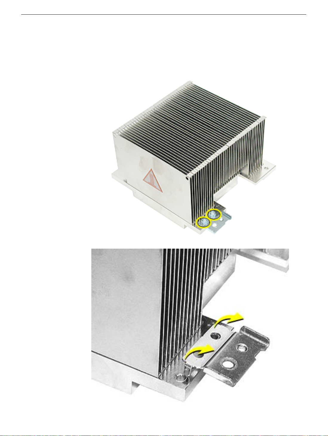
Power Mac G4 (FW 800):
Replacement Note: If you are replacing the heatsink in the Power Mac G4 (FW 800)
model, remove the two #2 Phillips screws at the heatsink bracket, and transfer the
bracket to the replacement heatsink.
92 - Power Mac G4 (Mirror/FW 800) Take Apart
Heatsink
Page 95

Power Mac G4 (FW 800), Best Configuration:
Replacement Note: If you are replacing the heatsink in the Best configuration of the
Power Mac G4 (FW 800) model, remove the two #2 Phillips screws at the heatsink
bracket, and transfer the bracket to the replacement heatsink. (Refer to previous
page.)
Heatsink
Power Mac G4 (Mirror/FW 800) Take Apart - 93
Page 96

Processor
Tools
No tools are required for this procedure.
Part Location
Preliminary Steps
Before you begin, do the following:
• Open the side access panel.
• Remove the heatsink.
• Remove the thermal grease (refer to Heatsink procedure).
94 - Power Mac G4 (Mirror/FW 800) Take Apart
Processor
Page 97

Procedure
1. Grasp the processor by the edges and lift slightly to disconnect it from the logic board.
2. Slide the processor toward the back panel and then lift the processor up and out of the
computer, being careful to clear the two mounting pegs.
Processor
Before Replacing the Processor
Important: Apple has determined a compatibility issue between the processor and certain
fabrication levels of the logic board on some Power Mac Server G4 (Mirrored Drive Doors)
and Power Mac G4 (Mirrored Drive Doors) products. Before ordering a replacement
processor for those models, refer to "What’s New" in Troubleshooting.
Power Mac G4 (Mirror/FW 800) Take Apart - 95
Page 98

Processor Stiffener
Tools
No tools are required for this procedure.
Part Location
Preliminary Steps
Before you begin, do the following:
• Open the side access panel.
• Remove the heatsink.
• Remove the processor.
96 - Power Mac G4 (Mirror/FW 800) Take Apart
Processor Stiffener
Page 99

Procedure
1. Lift the processor stiffener straight up off the two mounting pegs.
2. Remove the stiffener from the computer.
Processor Stiffener
Power Mac G4 (Mirror/FW 800) Take Apart - 97
Page 100

Logic Board
Note: This procedure pictures the Power Mac G4 (MIrrored Drive Doors) computer.
Although the logic board in the Power Mac G4 (FW 800) model has a somewhat different
shape, the steps are the same.
Tools
The only tool required for this procedure is a Phillips screwdriver.
Part Location
Preliminary Steps
Before you begin, open the computer and remove the following.
• DIMMs
• Video card
98 - Power Mac G4 (Mirror/FW 800) Take Apart
Logic Board
 Loading...