

Page 1

K
Service Source
PLW SC/NT/NTR/LS
Personal LaserWriter SC, Personal LaserWriter NT,
Personal LaserWriter NTR, Personal LaserWriter LS,
Personal LaserWriter LS/L
Page 2

K
Service Source
Basics
PLW SC/NT/NTR/LS
Page 3

Basics Product Information - 1
Product Information
The printers covered in this manual are
• Personal LaserWriter SC
• Personal LaserWriter NT
• Personal LaserWriter NTR
• Personal LaserWriter LS
• Personal LaserWriter LS/L
Compatibility
Not all parts are compatible among the five models. Refer to
Illustrated Parts for compatibility cross references.
The cassette feeder tray and its associated parts are optional
on the LS, LS/L, and NTR models.
Page 4
Basics Paper Paths - 2
Paper Paths
There are four paper paths in the Personal LaserWriter.
Paper is fed from the cassette or multipurpose tray and
delivered to the face-down or face-up delivery trays.
Note:
Face signifies image side. Default delivery is face-
down at the top of the printer.
Page 5
Basics LS–LS/L Identification - 3
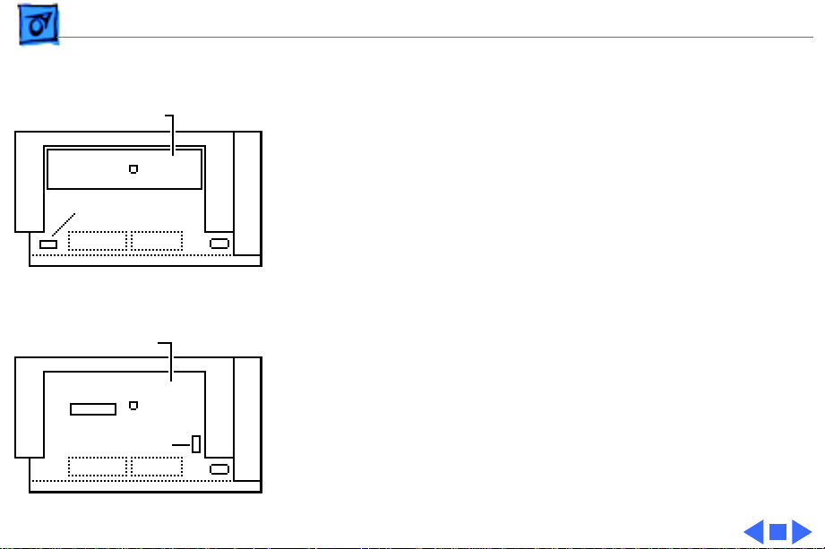
LS–LS/L Identification
I/O Board Bracket
Power Switch
Personal LaserWriter LS
Solid Rear Cover
Power Switch
Personal LaserWriter LS/L
The LS/L is a cost-reduced version of the LS but is sold and
packaged under the same LS name. Parts are not necessarily
interchangeable between the two models.
External distinguishing characteristics:
• LS: The power switch is on the left rear of printer; the
rear cover has an opening for an I/O board bracket and
displays the family number M2000.
• LS/L: The power switch is on the right rear of printer;
the rear cover is solid plastic and displays the family
number M2002.
Page 6
Basics Sensing System Theory - 4
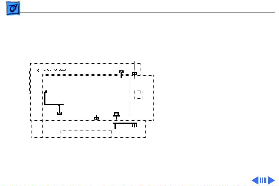
Sensing System Theory
PS502
PS13
PS12
PS501
PS11
PS901
There are six sensors in the
Personal LaserWriter: four
paper sensors and two
printer-open sensors. Each
consists of an actuator, a Ushaped photo interrupter,
and circuitry that communicates with the controller.
If the actuator is present
inside the U, the circuit
closes; if it is absent, the
circuit opens. In ready state
the appropriate circuit is
closed.
Page 7

Basics Sensing System Theory - 5
Paper sensors are actuated
as an arm or lever swings
against movement of paper.
Printer-open sensors are
PS11
PS12
actuated as the user shuts a
door or cover.
Illustrations on the
following cards show each
sensor as it would appear in
PS501
PS502
PS13
PS901
print ready state. Some
peripheral elements are
deleted for clarity.
Page 8
PLW SC/NT/NTR/LS Basics - 6
Actuator Tab on
Toner Cartridge
Photo Interrupter
PS11
Toner Cartridge Sensor
Actuator: Toner cartridge shutter flips into
position as front door closes.
Page 9
PLW SC/NT/NTR/LS Basics - 7
Photo
Interrupter
PS12
Delivery Unit Paper Sensor
Actuator: Sensing lever housed in fuser
assembly is tripped by paper exiting fuser.
Paper-Sensing Lever
Page 10
PLW SC/NT/NTR/LS Basics - 8
Photo
Interrupter
Paper-Sensing Lever
PS13
Pickup Unit Paper Sensor
Actuator: Sensing lever in feeder assembly
is tripped by paper entering feed cycle.
Page 11
PLW SC/NT/NTR/LS Basics - 9
Photo
Interrupter
PS501
Multipurpose Tray Sensor
Actuator: Sensing lever in multipurpose cable
assembly is tripped by manually fed paper.
Paper-Sensing Lever
(Shown in tripped position)
Page 12
PLW SC/NT/NTR/LS Basics - 10
Cover
Sensing
Arm
PS502
Face-Up Cover Sensor
Actuator: Sensing arm is tripped
by the closing of the face-up ocver.
Photo Interrupter
Page 13
PLW SC/NT/NTR/LS Basics - 11
Photo
Interrupter
PaperSensing Arm
PS901
Paper Cassette Sensor
Actuator: Sensing arm is tripped by the
insertion of loaded cassette tray.
Page 14
Basics Startup Test Pages - 12
Startup Test Pages
The Personal LaserWriter
SC, NT, and NTR generate a
startup test page 2 – 3
minutes after you switch on
the printer. The LS and LS/
L do not produce such a page.
In the NT and NTR the
startup test page also shows
unit-specific configuration
information. The following
pages describe each element
of the startup test pages.
Page 15
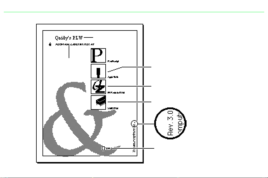
PLW SC/NT/NTR/LS Basics - 13
Ê
Printer Name
I/O Board
Type
NT/NTR Startup Test Page
Communication Protocol
RS-232 serial or AppleTalk
Fonts in ROM
Installed RAM
Version of ROM installed
Number of pages the I/O
board has produced
Page 16
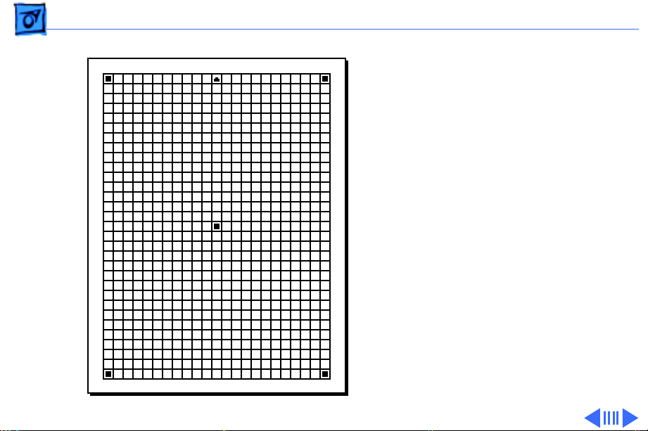
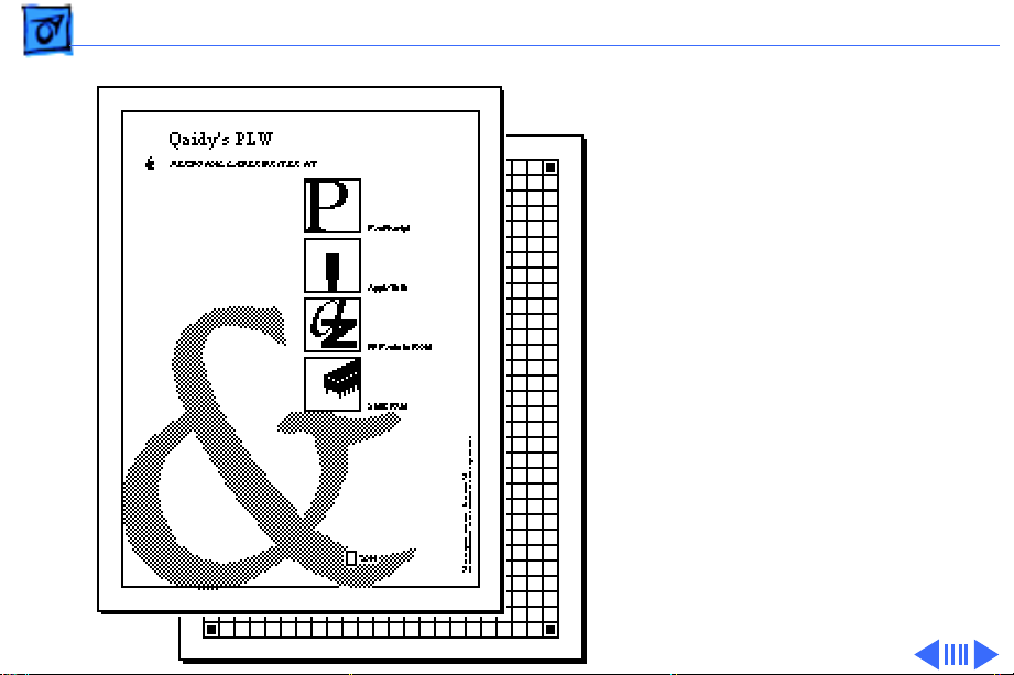
Basics Startup Test Pages - 14
The Personal LaserWriter
SC test page consists of a line
matrix. The printer
generates a test page only if
you set its SCSI address to 7
prior to switching on the
printer. It continues to
print until it is out of paper.
Note:
Be sure to set the SCSI
address back before
resuming printing.
SC Startup Test Page
Page 17
Basics Service Test Page - 15
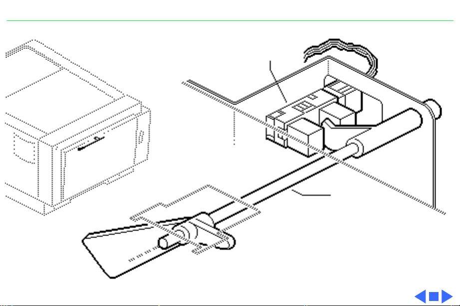
Service Test Page
Successful printing of a
service test page confirms
print engine operation.
There are three variations
in how you run a service test
page, depending on the
model you are servicing.
Each involves using a pencil
or similar dowel-shaped
tool to depress the service
test button on the DC
controller board (or serial
controller on the LS/L).
Service Test Page
Page 18
Basics Service Test Page - 16
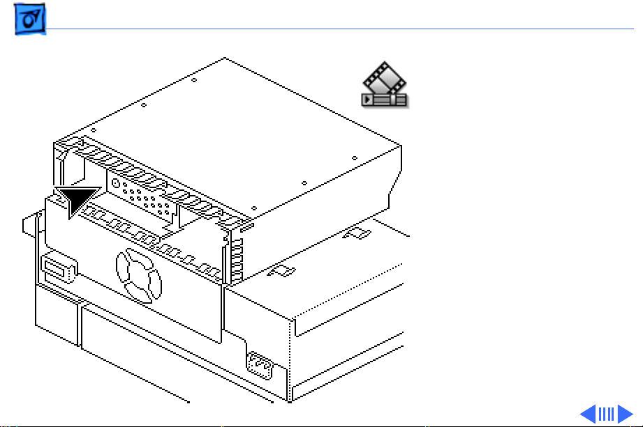
SC, NT, NTR
First remove the I/O board.
You can then access the test
button through the 1/4inch diameter opening in
the I/O shield.
SC, NT, NTR
Service Test Page
Page 19
Basics Service Test Page - 17
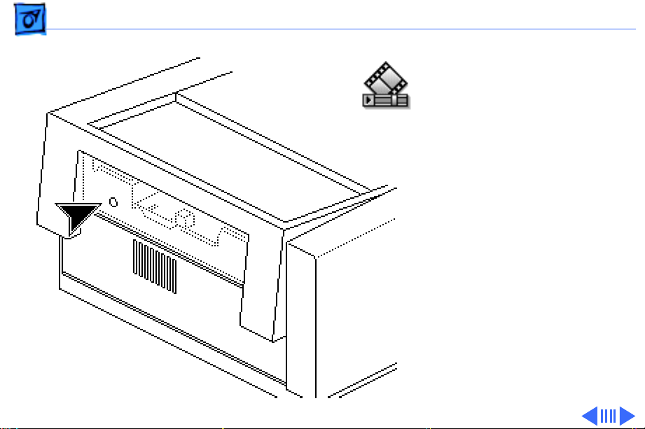
LS
First remove the I/O board
bracket. You can then access
the test button through the
1/4-inch diameter opening
in the end plate.
LS
Service Test Page
Page 20
Basics Service Test Page - 18
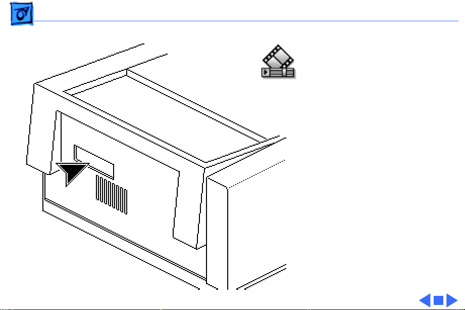
LS/L
First remove the test button
cover on the rear panel of
the printer. You can then
access the test button
through the opening in the
rear panel.
LS/L
Service Test Page
Page 21

K
Service Source
Specifications
PLW SC/NT/NTR/LS
Page 22

Specifications General - 1
General
Engine
Printing Method
Optical System
Resolution
Imaging Languages Supported
Canon P110 engine
Electrophotography using single-component dry toner
Semiconductor laser and a rotating dual-faced scanning mirror
300 dpi
SC: QuickDraw
NT: PostScript, HP LaserJet Plus, and a subset of Diablo 630
NTR: PostScript, HP LaserJet Plus, and a subset of Diablo 630
LS: QuickDraw
LS/L: QuickDraw
Page 23

Specifications Intro Dates - 2
Intro Dates
SC and NT
LS
LS/L and NTR
July 1990
March 1991
March 1992
Page 24

Specifications Logic Board - 3
Logic Board
CPU
DRAM
SC: Motorola 68000 microprocessor (7.275 MHz)
NT: Motorola 68000 microprocessor (12 MHz)
NTR: N/A
LS: N/A
LS/L: N/A
SC: 1 MB
NT: 2 MB, expandable to 8 MB
NTR: 3 MB, expandable to 4 MB
LS: 512K, expandable to 1 MB
LS/L: 512K, expandable to 1 MB
Page 25

Specifications Logic Board - 4
ROM
I/O
SC: 32K
NT: 1.25 MB
NTR: 3 MB
LS: N/A
LS/L: N/A
SC: SCSI
NT: LocalTalk, RS-232, RS-422
NTR: LocalTalk, RS-232, RS-422, Centronics parallel
LS: RS-422
LS/L: RS-422
Page 26

Specifications Performance - 5
Performance
Printing Speed
Print Delivery
Life Expectancy
4 pages per minute maximum; actual performance depends on the
application
Face-down or face-up (manually selectable)
150,000 pages with no monthly page limit
Page 27

Specifications Paper - 6
Paper
Paper W eights
Cassette Sizes
Capacity In
Capacity Out
Cassette feed: 20 lb., single-sheet, photocopy bond
Manual feed: 20-28 lb., letterhead and colored stock, medium-
weight transparency material, envelopes, and labels
US letter standard; legal, A4, B5, and envelope cassettes optional
Cassette: 250 sheets
Manual: 50/70 sheet capacities
Envelope cassette: 15 envelopes, minimum size 86 x 178 mm
(3.5 x 7 in.), maximum size 188 x 267 mm (7.4 x 10 in.)
Face-down tray: 50 sheets
Face-up tray: 20 sheets
Page 28

Specifications Built-In Fonts - 7
Built-In Fonts
SC, LS, and LS/L
NT
NTR
N/A
Times, Helvetica, Helvetica Narrow, Courier, Symbol, Palatino,
ITC Avant Garde, Gothic, ITC Bookman, New Century
Schoolbook, ITC Zapf Chancery, and ITC Zapf Dingbats
Times, Helvetica, Helvetica Narrow, Courier, Symbol, Palatino,
ITC Avant Garde, Gothic, ITC Bookman, New Century
Schoolbook, ITC Zapf Chancery, ITC Zapf Dingbats, and IBM PC
Graphics Extended Character Set (ECS)
Page 29

Specifications Environmental - 8
Environmental
Temperature
Humidity
Noise Level
50-90.5° F (10-32.5° C)
20-80% relative humidity
Printing: Under 53 dB(A)
Standby: Under 43 dB(A)
Page 30

Specifications Electrical - 9
Electrical
Line V oltage
Power Consumption
US/Japan: 100/115 V, 50/60 Hz
Europe/Australia: 220/240 V, 50 Hz
600 W maximum (100/115 V)
550 W maximum (220/240 V)
Page 31

Specifications Physical - 10
Physical
Dimensions
Weight
Height: 8 in. (20.3 cm), 9.8 in. (24.8 cm) with cassette feeder
Width: 15 in. (38 cm)
SC, NT, and NTR: 32 lb. (15 kg)
LS and LS/L: 31 lb. (14.5 kg)
Page 32

K
Service Source
Troubleshooting
PLW SC/NT/NTR/LS
Page 33

Troubleshooting Status Panel LEDs - 1
Status Panel LEDs
On the next page is an illustration that shows the possible LED
patterns that can occur with the Personal LaserWriter.
Note:
Refer to "Print Engine Check" in Flowcharts for full
troubleshooting paths.
Page 34

Troubleshooting Status Panel LEDs - 2
Front Access Door Open
No Toner Cartridge
or Face-Up Cover Open
System Theory” in Basics.)
LS and LS/L display only
these configurations
(see “LS Error Messages”)
(see PS11/PS502 in “Sensing
Ready Paper
Out
Paper
Jam
I/O Board
Alternating
FLASH
Fuser or
Laser/Scanner
Simultaneous
FLASH
Page 35

Troubleshooting Capacitor Discharge - 3
Capacitor Discharge
When there is a failure of the fusing system, the DC controller
board shuts off current to the fuser roller heater and charges
capacitor C212 to prevent overheating (C209 on the LS/L serial
controller board).
DC Controller Board
(SC, NT, NTR, LS)
C212
C209
Serial Controller
(LS/L)
Page 36

Troubleshooting Capacitor Discharge - 4
Before you can use the printer again, you must switch the power
off and wait 3 minutes for the capacitor to discharge. If you do not
want to wait, you can manually discharge the capacitor as
described below.
Remove the top cover, locate the capacitor described on the
previous page, and carefully jumper the two wires at the base of
the capacitor as shown on the next page.
Note:
Remove the I/O board and/or shield if you are servicing an
SC, NT, or NTR. Remove the PCB shield if you are servicing an LS/
L.
Caution:
components around the capacitor. There are many different tools
that can be used to discharge the capacitor: a flat blade
screwdriver, paper clip, or aluminum foil doubled over. The tool
illustrated is a length of lead solder. It has the advantage of being
ductile and is less apt to damage the controller board.
Take care not to damage the board tracings or the
Page 37

Troubleshooting Capacitor Discharge - 5
Capacitor C212
(C209 on LS/L)
Page 38

Troubleshooting LS Error Messages - 6
LS Error Messages
The SC, NT, and NTR display errors through status panel readouts
(see “Status LEDs”). The LS and LS/L display errors through
alert dialogs on the host computer.
For other hardware-related messages, go to “Print Engine
Check.” For non-hardware error messages, follow the prompt
given, or call the Apple Technical Assistance Center.
Note:
If you are having communication problems with an LS,
make sure that you have used the installer to load the printer
driver.
Page 39

Troubleshooting Roller Diameters - 7
Roller Diameters
Repetitive printing defects can often be isolated by measuring the
tracking left by rollers. On the next page is a diagram that shows
all the rollers in the Personal LaserWriter that come into contact
with paper. The dimension given is the distance between tracks.
Page 40

Troubleshooting Roller Diameters - 8
Toner Cartridge Rollers
1.5" (38 mm): primary charging roller
2.0" (51 mm): developer roller
3.7" (94 mm): photosensitive drum
Fuser Assembly
2.15" (54 mm): lower fuser roller
2.9" (74 mm): upper fuser roller
Other Rollers
1.9" (49 mm): paper feed roller
2.05" (52 mm): transfer roller
Page 41

Troubleshooting Drum Check - 9
Drum Check
Interrupting a print cycle and inspecting the photosensitive drum
can help isolate the cause of print quality problems. If the image
on the surface of the drum exhibits the same problem as the
printed page, the fault is before the drum, probably somewhere in
the scanning system.
If the image on the drum is okay, the fault is after the drum,
probably in the fuser assembly, transfer roller, or high-voltage
power supply.
Note:
Refer to “Roller Diameters” in this chapter for further
quick-check troubleshooting tips.
Page 42

Troubleshooting Flowcharts - 10
Flowcharts
The flowcharts for this manual are contained in an interactive file
called “PLW SC/NT/NTR/LS Flowcharts.” This file has been
derived from the original version of Service Source but is a
standalone self-launching application. To launch this file, click
the button below..
Page 43

220/240V
Models
CB101
BK BKCB101
TB101 TB102
L
IL101
N
RT101
TB102
C101
C102
Power Supply
C101
C102
L101
Door
Switch
Unit
L101
R101
J11
VZ101
ACH
ACLFU1
FSRDRV
Power
Switch
SW11
256
3
TB103
YB105
TB106
TB104
C104 Q101
TB107
J102
1
2
J152
TB109-2
2
1
TB109-1
+5V
TB108
Door
Switch
L102
2
J101
SQ101C103
Fuser
PCB
Assembly
TB501
TB502
1
1A 3A
1B 3B
SW101
R102
R103
SSR101
426
1
R104
Front Access Door
Fuser Assembly
TP1
J501
1
RT501
TP2
3
Roller
Clutch
Solenoid
RT502
TH1
SL501Pick-Up
Fixing
DC PCB
H1
1
1
TB503
RT505 RT102
D502
RT503 RT504
3
2
J5802
3
2
TB504
D501
J503
132
PS501
C
GND
Multi-Purpose
Tray
Paper
Sensor
A
J504
Cartridge Sensor
Delivery Paper Sensor
PS11
PS12
CGA
CGA
J13
123
123
12312
TB702 J12
TB703
R701
3
R702
PS502
C
-1-3-2
Exhaust Fan
123
J701
Driver
VR701
GND
Fan
A
Delivery
Unit
Door
Open
Sensor
FM11
EP-L Cartridge
Primary Charging
Roller
Drum
Developing
Cylinder
Transfer
Charging
Roller
RT103
RT104
FT101
1
4
P. Primary
TB601
SG
T. Transfer
J602
HVT
+24V
GND
HVACVR+8V
123456789
J601
RT105
J602
2
D. Development
HVDC
HVT1
HVD
HVT2
10
HVT3
Cassette Paper Feeder
GND
SW903
A
R902
R901
SW902
SW901
Cassette
Feed
Roller
Clutch
Solenoid
SL902
5
4
Q902 Q901
Cassette
Paper
Sensor
PS901
C
132
132
J902 J905
R904
Cassette Size
Sensing
Switches
R903
123456789
Cassette
Pick-Up
Roller
Clutch
Solenoid
SL901
7
6
Cassette
Paper
Feeder
PCB
Main Motor
+5V
+5V
BRBRBL
GND
GND
BL
J212
4
3
2
1
GND
+24V
GND
+24V
GND
+12V
GND
BLBLRRBLORBLBRY
123456789
GND
GND
GND
GND
+24V
+24V
+12V
SG
PPRDY
TOP
A1A2A3A4A5A6A7A8A9
J301
J302
GND
GND
+5V
+5V
LED Power
LED 1
LED 2
123
123
4
4
LED 3
J303
Display Panel
+5V
FSRDRV
+5V
FSRDRV
STS
CBSY
N.C.
VDOI
CCLK
/CCLK
/PRFD
/VDO
J304
A1A2A3A4A5A6A7A8A9
PS13
Pick-up Unit
Paper Sensor
C
GND
A
123
J208 J14
123
GND
PFA
PFSNS
PRFD
RESET
BOO
RDY
SBSY
PCLK
B1B2B3B4B5B6B7B8B9
A10
Interconnect PCB
Reserved
/CBSY
/STS
/TOP
/PPRDY
LED Power
PRNT
LED 1
A10
CPRDY
CMD
Reserved
A11
GND
A12
N.C.
N.C.
TSTPNT
B10
GND
GND
GND
GND
A13
A14
A15
A16
I/O Board
123456789
J209
POA
GND
PFDRV
/CMD
FSRTH
/CPRDY
POUT
/PRNT
GND
/PCLK
DOSNSE
/SBSY
/RDY
+24V
Reserved
Reserved
B1B2B3B4B5B6B7B8B9
123456789
TB701J213
10
123456789
+8V
DOA
GND
+12V
DC Controller
/BD
LED 2
LED 3
+5V
B11
B12
B10
+5V
B13
+5V
+5V
B14
POSNS
DOSNSE
+5V
B15
FMDRV
+5V
B16
CNTD
VR
GND
Density
Adj.
PCB
1234567
1234567
J401 J202
J204
+5V
GND
Laser
Driver
123456789
J206
Optical Fiber
GND
+24V
APCIN
LSRPWR
VDOUT
GND
+8V
M1
SCNCLK
SCNTAC
J205 J901
SCNON
+12V
1
1
123456789
+5V
+5V
+24V
OPSIZ2
OPMD
OPSIZ1
OPSIZ0
OPPOUT
+5V
+12V
123456789
J207
10
VR
+8V
HVD
HVTI
HVT2
HVDC
HVT3
GND
65432
65432
J301 J203
HVAC
+24V
OPCD
GND
GND
RDYNH
12345
J210
COA
LPC
TSS
TSC
+8V
6
OAOBOA
OB
COB
APCIN
TSTPE
TSTPNT
10
11
12
Scanner
Motor Unit
Personal LaserWriter SC/NT
Wiring Diagram
Page 44

220/240V
Models
CB101
BK BKCB101
TB101 TB102
L
IL101
N
RT101
TB102
C101
C101
L101
C102
Power Supply
Unit
L101
C102
Door
Switch
R101
Power
Switch
J11
VZ101
ACH
ACLFU1
FSRDRV
SW11
256
3
TB103
YB105
TB106
TB104
C104 Q101
TB107
J102
1
2
J152
TB109-2
2
1
TB109-1
+5V
TB108
Door
Switch
L102
J101
SQ101C103
Fuser
PCB
Assembly
TB501
TB502
2
1A 3A
1B 3B
SW101
R102
SSR101
426
R104
1
R103
1
Pick-Up
Roller
Clutch
Solenoid
Front Access Door
Fuser Assembly
TP1
J501
1
RT501
TP2
3
RT502
SL501
TH1
Fixing
DC PCB
H1
1
1
TB503
RT505 RT102
D502
RT503 RT504
3
2
3
2
TB504
J5802
D501
J503
132
PS501
C
GND
MultiPurpose
Tray
Paper
Sensor
A
J504
Cartridge Sensor
Delivery Paper Sensor
PS11
PS12
CGA
CGA
J13
123
123
12312
TB702 J12
TB703
R701
3
R702
PS502
C
GND
A
-1-3-2
Exhaust Fan
123
J701
Fan
Driver
VR701
Delivery
Unit
Door
Open
Sensor
FM11
EP-L Cartridge
Primary Charging
Roller
Drum
Developing
Cylinder
Transfer
Charging
Roller
RT103
RT104
FT101
1
4
J602
TB601
SG
P. Primary
T. Transfer
HVT
+24V
GND
HVACVR+8V
123456789
J601
RT105
J602
2
D. Development
HVDC
HVT1
HVD
HVT2
10
HVT3
Cassette Paper Feeder
GND
SW903
A
R902
R901
SW902
SW901
Cassette
Feed
Roller
Clutch
Solenoid
SL902
5
4
Q902 Q901
Cassette
Paper
Sensor
PS901
C
132
132
J902 J905
R904
Cassette Size
Sensing
Switches
R903
123456789
Cassette
Pick-Up
Roller
Clutch
Solenoid
SL901
7
6
Cassette
Paper
Feeder
PCB
Main Motor
Display
Panel
J208 J14
PS13
C
123
123
PFSNS
GND
GND
Pick-up Unit
Paper Sensor
A
PFA
123456789
J209
GND
+24V
POUT
FSRTH
PFDRV
GND
POA
10
GND
DOSNSE
123456789
TB701J213
123456789
+8V
DOA
+12V
+5V
POSNS
DOSNSE
Density
Adj.
M1
PCB
J204
VR
GND
CNTD
FMDRV
123456789
J206
Optical Fiber
VR
GND
+24V
HVAC
+8V
HVDC
HVTI
HVD
10
HVT2
J205 J901
HVT3
123456789
+5V
+24V
OPSIZ2
OPSIZ1
OPSIZ0
OPMD
OPPOUT
OPCD
GND
12345
J210
COA
6
OAOBOA
OB
COB
GND
+24V
GND
+24V
GND
BLBLRRBLORBLBRY
123456789
J212
GND
GND
GND
+24V
+24V
+12V
+12V
GND
GND
+5V
+5V
FSRDRV
FSRDRV
DC Controller
SG
PPRDY
TOP
STS
CBSY
N.C.
VDO
CCLK
PRFD
N.C.BDRDY
SBSY
PCLK
PRNT
CPRDY
CMD
+5V
N.C.
N.C.
A1A2A3A4A5A6A7A8A9
1
1
2
2
3
3
4
4
LED Power
LED 1
LED 2
LED 3
J301
J803
B1B2B3B4B5B6B7B8B9
A10
I/O Board
B10
+5V
GND
APCIN
LSRPWR
1234567
1234567
J401 J202
Laser
Driver
VDOUT
GND
+8V
GND
SCNCLK
SCNTAC
SCNON
65432
65432
J301 J203
Scanner
Motor Unit
+12V
+5V
1
1
+5V
+24V
GND
RDYNH
LPC
+12V
123456789
J207
TSS
TSC
+8V
APCIN
10
TSTPE
11
TSTPNT
12
Personal LaserWriter LS
Wiring Diagram
Page 45

K
Service Source
T ak e Apart
PLW SC/NT/NTR/LS
Page 46

Take Apart Top Cover - 1
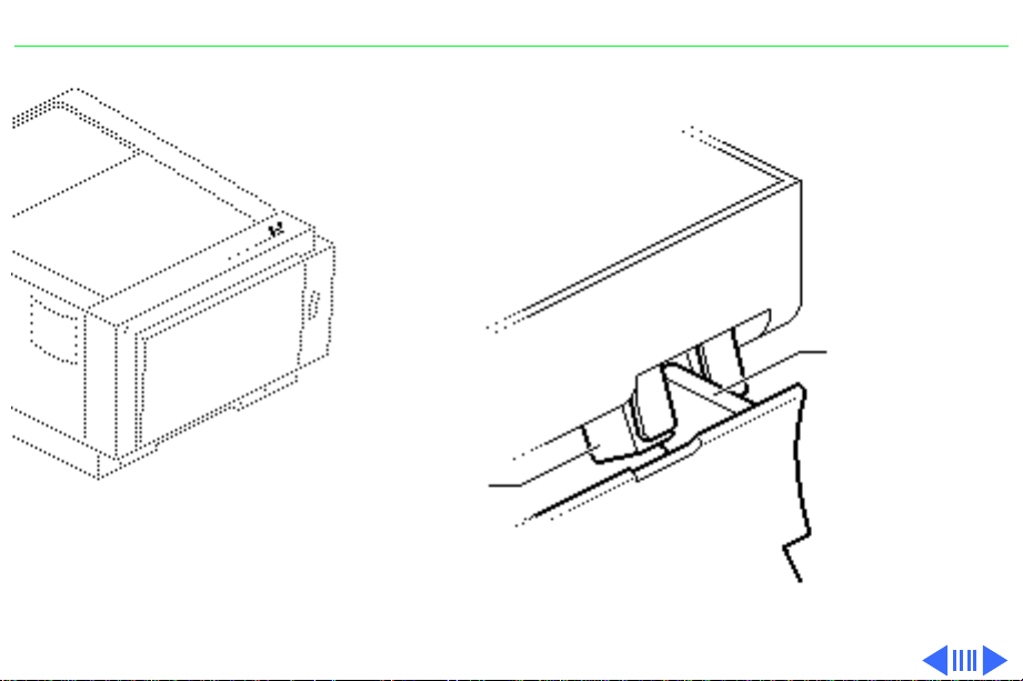
Top Cover
Top Cover
This topic applies to all
models of the printer.
No preliminary steps are
required before you begin
this procedure.
Page 47

Take Apart Top Cover - 2
1 Open the front access
door.
2
Note:
There is a pin on
the inside of the rear
panel that seats in a
notch in the chassis. You
must shimmy the cover
about an inch toward the
rear of the printer to
unseat this pin before
you can lift off the cover.
Remove the two screws
and lift off the top cover.
Page 48

Take Apart Front Cover - 3
Front Cover
This topic applies to all
models of the printer.
No preliminary steps are
required before you begin
this procedure.
1 Open the front access
door.
Front Cover
Page 49

Take Apart Front Cover - 4
2 Remove the two screws
that secure the front
Holding
Tab
cover to the front access
door. Lift up the facedown delivery assembly
and using needlenose
pliers release the
holding tab.
3 Lift off the front cover.
Face-Down
Delivery
Assembly
Front Cover
Page 50

Take Apart Front Cover - 5
Screw
Mount
Grooves
Right Holding Notch
Front Door
Replacement Note:
Lower
the multipurpose tray and
remove the face-up delivery
tray. Insert the right
holding tab first, then
swing the cover to the left,
making sure that the two
screw mounts align with the
grooves in the side of the
door. Press firmly until the
front cover snaps into place.
Page 51

Take Apart LED Cover - 6
LED Cover
This topic applies to all
models of the printer.
LED Cover
Before you begin, remove
the front cover.
Page 52

Take Apart LED Cover - 7
1 Remove the two screws
that secure the LED
cover to the front access
door.
LED Cover
Page 53

Take Apart LED Cover - 8
2 Lift off the LED cover
and disconnect the LED
cable from the LED
holder.
LED Cable
Connector
Page 54

Take Apart Cassette Feeder Tray - 9
Cassette Feeder Tray
This topic applies to all
models of the printer.
No preliminary steps are
required before you begin
this procedure.
Note:
The cassette feeder
tray and its associated parts
are optional on the LS, LS/L,
and NTR models.
Cassette Feeder Tray
Page 55

Take Apart Cassette Feeder Tray - 10
1 Turn the printer upside
down so that it is resting
on its top.
2 Remove the four
mounting screws and
lift off the cassette
Cassette
Feeder
Tray
feeder tray.
Page 56

Take Apart Pedestal Covers - 11
Pedestal Covers
Cassette
Stop
Cover
Left
Bottom
Cover
Right
Bottom
Cover
This topic applies to all
models of the printer.
Before you begin, remove
the cassette feeder tray.
Note:
The cassette feeder
tray and its associated parts
are optional on the LS, LS/L,
and NTR models.
Page 57

Take Apart Pedestal Covers - 12
1 Unhook the spring from
the cassette feeder tray,
Cassette Stop Cover
and remove the cassette
stop cover.
Spring
Page 58

Take Apart Pedestal Covers - 13
2
Caution:
Be careful not
to damage the cassette
Cassette
Microswitches
microswitches when
removing or replacing
the right bottom cover.
If you need to take apart
the right bottom cover,
remove the three
screws that secure it to
the cassette feeder tray.
3 Lift off the right bottom
cover.
Right Bottom Cover
Page 59

Take Apart Pedestal Covers - 14
4 If you need to take apart
the left bottom cover,
remove the two screws
that secure it to the
Left Bottom Cover
cassette feeder tray.
5 Lift off the left bottom
cover.
Page 60

Take Apart Cassette Feeder Roller Shaft - 15
Cassette Feeder Roller Shaft
This topic applies to all
models of the printer.
Before you begin, remove
the following:
• Cassette feeder tray
• Pedestal covers
Note:
The cassette feeder
tray and its associated parts
are optional on the LS, LS/L,
and NTR models.
Cassette Feeder Roller Shaft
Page 61

Take Apart Cassette Feeder Roller Shaft - 16
1 Using a small
screwdriver or gripring pliers, remove the
E-rings at each end of
Feeder
Roller
Shaft
the feeder roller shaft
(opposite end not
shown).
E-Ring
2 Slide off the two white
gears.
White
Gears
Page 62

Take Apart Cassette Feeder Roller Shaft - 17
3 Remove the holding pin.
4 Unhook the three plastic
feeder roller clamps
Feeder
Roller
Shaft
(rightmost clamp is
shown).
Roller
Clamp
Holding Pin
Page 63

Take Apart Cassette Feeder Roller Shaft - 18
5 Slide the bushings off
each end of the feeder
roller shaft (opposite
end not shown) and
Feeder
Roller
Shaft
Bushing
remove the shaft from
the cassette feeder tray.
Page 64

Take Apart Cassette Pickup Roller Shaft - 19
Cassette Pickup Roller Shaft
This topic applies to all
models of the printer.
Before you begin, remove
the following:
• Cassette feeder tray
• Pedestal covers
Note:
The cassette feeder
tray and its associated parts
are optional on the LS, LS/L,
Cassette Pickup
Roller Shaft
and NTR models.
Page 65

Take Apart Cassette Pickup Roller Shaft - 20
Pickup Roller
Shaft
Pickup Clutch Assembly
Setscrew E-Ring
1 Using a small
screwdriver or gripring pliers, remove the
E-rings at each end of
the pickup roller shaft
(opposite end not
shown).
2
Note:
Do not lose the
small metal holding pin
mentioned in the
following step. You will
need the pin when
replacing the pickup
roller.
Using a 1.5 mm Allen
wrench, loosen the
setscrew and remove the
Page 66

Take Apart Cassette Pickup Roller Shaft - 21
clutch assembly. The
holding pin from the
roller shaft will fall into
your hand.
Page 67

Take Apart Cassette Pickup Roller Shaft - 22
Pickup Roller
Shaft
Bushing
3 Slide the bushings off
each end of the pickup
roller shaft (opposite
end not shown) and
remove the shaft from
the cassette feeder tray.
Page 68

Take Apart Cassette Pickup Roller Shaft - 23
Pickup Roller
Pickup Clutch Assembly
0.2 mm
Replacement Note:
When
replacing the pickup roller
shaft, give special care to
the following:
• Rotate the roller shaft
so that the crescentshaped pickup rollers
protrude through the
sheet metal.
• Be careful not to let
the holding pin slide
out of the shaft when
sliding the pickup
roller clutch onto the
roller shaft.
• Place a 0.2-mm
thickness gauge
between the cassette
Page 69

Take Apart Cassette Pickup Roller Shaft - 24
pickup roller clutch
and the E-ring.
• Adjust the setscrew so
that the distance
between the pickup
roller clutch and the
E-ring is 0.2 mm.
Then tighten the
setscrew into position.
Page 70

Take Apart Cassette Feeder Board - 25
Cassette Feeder Board
Cassette Feeder
Board
This topic applies to all
models of the printer.
Before you begin, remove
the following:
• Cassette feeder tray
• Cassette stop cover
• Right bottom cover
Note:
The cassette feeder
tray and its associated parts
are optional on the LS, LS/L,
and NTR models.
Page 71

Take Apart Cassette Feeder Board - 26
1 Remove the four black
screws that secure the
cassette feeder board to
Cassette Feeder Board
the feeder tray.
2 Disconnect connector
J902.
3 Remove the cassette
feeder board from the
cassette feeder tray.
J902
Cassette Feeder Tray
Page 72

Take Apart I/O Board (SC, NT, NTR) - 27
I/O Board (SC, NT, NTR)
I/O Board (SC,
NT, NTR)
This topic applies to the only
SC, NT, and NTR models.
Before you begin, remove
the top cover.
Note:
If the I/O board is
removed from the printer,
the LEDs no longer function.
Page 73

Take Apart I/O Board (SC, NT, NTR) - 28
1 Loosen the two screws
I/O Board
that secure the I/O board
to the shield.
I/O Shield
2 Handling the I/O board
only by the metal
bracket, carefully slide
the I/O board out of the
I/O shield.
Note:
Before returning an
I/O board to Apple, remove
the metal connector
bracket. Keep this bracket
and install it on the
replacement I/O board. If
you are replacing an NTR
board that has Rev. 4.0
ROMs, you need to remove
Page 74

Take Apart I/O Board (SC, NT, NTR) - 29
the ROMs and install them on
the replacement board.
Refer to “NTR ROM
Upgrade” in Upgrades for
complete information.
Replacement Note:
Reinstall the I/O board
component-side down.
Page 75

Take Apart I/O Shield (SC, NT, NTR) - 30
I/O Shield (SC, NT, NTR)
I/O Shield
(SC, NT, NTR)
This topic applies only to the
SC, NT, and NTR models.
Before you begin, remove
the following:
• Top cover
• I/O board
Page 76

Take Apart I/O Shield (SC, NT, NTR) - 31
1 Remove the five
mounting screws and
lift the I/O shield from
the chassis.
I/O Shield
Page 77

Take Apart End Plate (SC, NT, NTR) - 32
End Plate (SC, NT, NTR)
This topic applies only to the
SC, NT, and NTR models.
Before you begin, remove
the following:
End Plate
(SC, NT, NTR)
• Top cover
• I/O board
• I/O shield
Page 78

Take Apart End Plate (SC, NT, NTR) - 33
1 Remove the four
mounting screws and
lift the end plate out of
the chassis.
End Plate
Page 79

Take Apart I/O Shield (LS) - 34
I/O Shield (LS)
This topic applies only to the
LS model.
I/O Shield (LS)
Before you begin, remove
the top cover.
Page 80

Take Apart I/O Shield (LS) - 35
1 Remove the seven screws
that secure the I/O
shield and lift the I/O
shield from the printer.
I/O Shield
Page 81

Take Apart I/O Board (LS) - 36
I/O Board (LS)
This topic applies only to the
I/O Board (LS)
LS model.
Before you begin, remove
the following:
• Top cover
• I/O shield (LS)
Page 82

Take Apart I/O Board (LS) - 37
1 Disconnect the cable
I/O Board
J803
from connector J803 on
the I/O board.
2 Remove the three screws
that secure the I/O board
in place.
3 Holding the board only
by the edges, disengage it
from the I/O bracket.
Gently lift straight up,
and disconnect the I/O
board from the
controller board.
Page 83

Take Apart End Plate (LS) - 38
End Plate (LS)
End Plate (LS)
This topic applies only to the
LS model.
Before you begin, remove
the following:
• Top cover
• I/O shield (LS)
• I/O board (LS)
Page 84

Take Apart End Plate (LS) - 39
1 Remove the five
mounting screws and
lift the end plate out of
the chassis.
Page 85

Take Apart PCB Shield - 40
PCB Shield
This topic applies only to the
LS/L model.
PCB Shield
Before you begin, remove
the top cover.
Page 86

Take Apart PCB Shield - 41
1 Remove the two screws
Duct Plate
that secure the duct plate
to the printer chassis.
Lift out the duct plate.
Page 87

Take Apart PCB Shield - 42
PCB Shield
2 Remove the six screws
that secure the PCB
shield to the printer
chassis. Lift out the PCB
shield.
Page 88

Take Apart Serial Controller - 43
Serial Controller
Serial Controller
This topic applies only to the
LS/L model.
Before you begin, remove
the following:
• Top cover
• PCB shield
Page 89

Take Apart Serial Controller - 44
±
Warning:
Never
disconnect optical fiber
cable J204 when the
printer is powered on. Its
invisible laser beam can
damage your eyes.
1 Disconnect the following
cables from the serial
controller board:
• Laser assembly board
cable from J202
J204
J202
J206
J203
J205
J209
J208
J210
J212
J213
J215
• Scanner motor board
Serial Controller Board
cable from J203
• Optical fiber cable
from J204
• Cassette feeder board
cable from J205
Page 90

Take Apart Serial Controller - 45
• High-voltage power
supply cable from
J206
• Paper pickup sensor
cable from J208
• Fuser assembly cable
from J209
J204
J206
J203
J205
J209
J208
J210
• Main motor cable
J202
J212
J213
from J210
• DC power supply
cable from J212
J215
• Fan-and-sensor
board cable from
Serial Controller Board
J213
• Status light cable
from J215
Page 91

Take Apart Serial Controller - 46
2 Remove the four
mounting screws and
lift the board from its
mounting plate.
Page 92

Take Apart Serial Controller Mounting Plate - 47
Serial Controller Mounting Plate
This topic applies only to the
LS/L model.
Before you begin, remove
the following:
Serial Controller
Mounting Plate
• Top cover
• PCB shield
±Warning: Never
disconnect optical fiber
cable J204 when the
printer is on. Its invisible
laser beam can damage your
eyes.
Page 93

Take Apart Serial Controller Mounting Plate - 48
1 Disconnect the following
cables from the serial
controller board:
• Laser assembly board
cable from J202
J205
J206
J204
J203
J202
J209
J208
J210
J215
J212
J213
• Scanner motor board
cable from J203
• Optical fiber cable
from J204
• Cassette feeder board
cable from J205
• High-voltage power
supply cable from
J206
Serial Controller Board
• Paper pickup sensor
cable from J208
• Fuser assembly cable
from J209
Page 94

Take Apart Serial Controller Mounting Plate - 49
• Main motor cable
from J210
• DC power supply
cable from J212
• Fan-and-sensor
J205
J206
J204
J203
J202
J209
J208
J210
J212
J213
board cable from
J213
• Status light cable
from J215
2 Remove the cables from
the cable retainer near
J212.
J215
Serial Controller Board
Page 95

Take Apart Serial Controller Mounting Plate - 50
3 Remove the six screws
that secure the serial
controller mounting
plate to the chassis. Lift
the mounting plate out
of the printer.
Replacement Note: The
two metal tabs along the
rear mate into the
chassis on the LS/L
model.
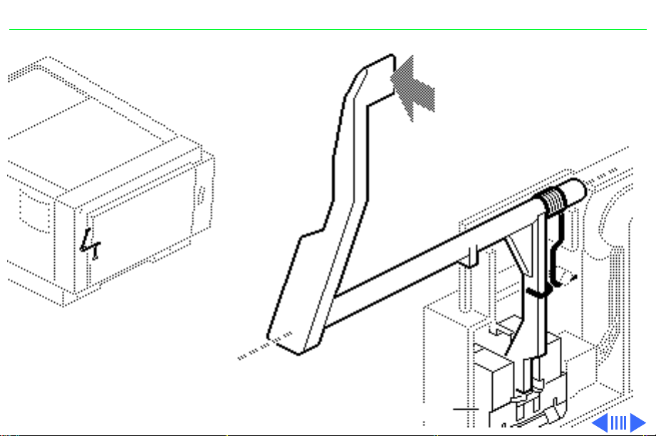
Page 96

Take Apart Fan - 51
Fan
This topic applies to all
models of the printer.
Before you begin, remove
the top cover.
Fan
Page 97

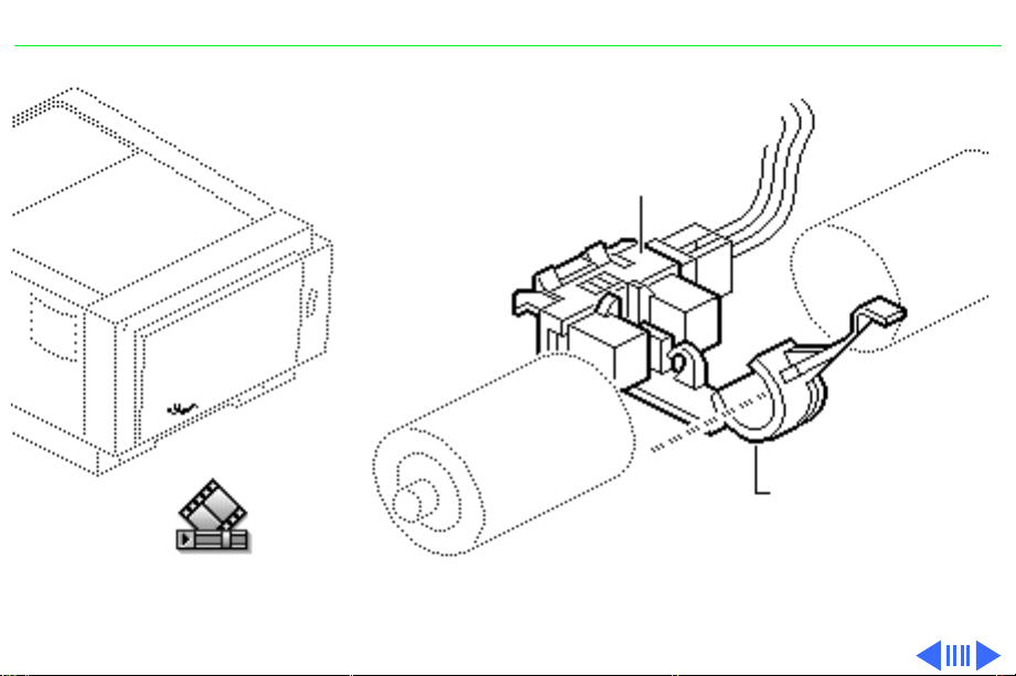
Take Apart Fan - 52
1 Remove the two fan
J701
mounting screws.
2 Using small diagonal
cutters, carefullly cut
the tie-wrap that
secures the fan cable.
3 Disconnect fan
connector J701 from the
density-adjusting board.
Page 98

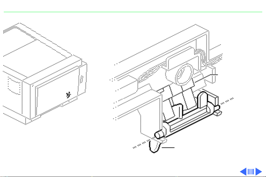
Take Apart Fan - 53
4 Unlatch the holding tab
and lift out the fan
bracket and the fan.
Replacement Note:
• Install the fan with
the label facing out.
• Place the gold-colored
grounding plate over
the fan bracket.
Holding
Tab
Page 99

Take Apart Sensor Mounting Plate - 54
Sensor Mounting Plate
Sensor Mounting Plate
This topic applies to all
models of the printer.
Before you begin, remove
the top cover.
Page 100

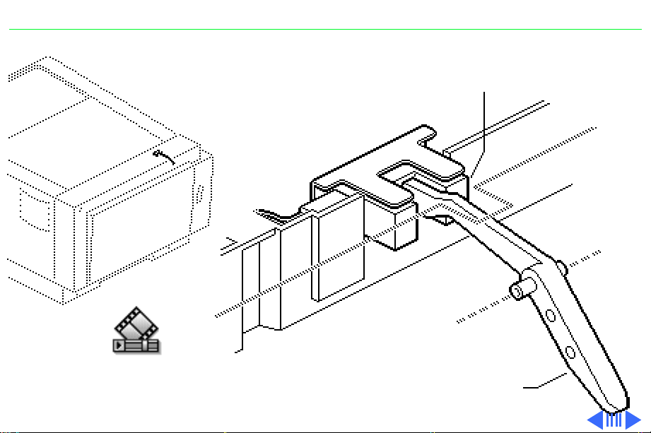
Take Apart Sensor Mounting Plate - 55
1 Remove the two black
mounting screws and
washers and slightly lift
the sensor mounting
plate.
Sensor
Mounting
Plate
2 Disconnect connectors
J11 and J12 and lift out
the sensor mounting
plate.
Replacement Note:
Connect connectors J11
and J12 before seating
the sensor mounting
plate.
Connector
J12
Connector
J11
 Loading...