

Page 1

Logic Pro 7
Plug-In Reference
Page 2

Apple Computer, Inc.
© 2004 Apple Computer, Inc. All rights reserved.
Under the copyright laws, this manual may not be
copied, in whole or in part, without the written consent
of Apple. Your rights to the software are governed by
the accompanying software licence agreement.
The Apple logo is a trademark of Apple Computer, Inc.,
registered in the U.S. and other countries. Use of the
“keyboard” Apple logo (Option-Shift-K) for commercial
purposes without the prior written consent of Apple
may constitute trademark infringement and unfair
competition in violation of federal and state laws.
Every effort has been made to ensure that the
information in this manual is accurate. Apple Computer,
Inc. is not responsible for printing or clerical errors.
Apple Computer, Inc.
1 Infinite Loop
Cupertino, CA 95014-2084
408-996-1010
www.apple.com
Apple, the Apple logo, Aqua, Final Cut, Final Cut Pro,
FireWire, iBook, iMac, iPod, iTunes, Logic, Mac,
Macintosh, Mac OS, PowerBook, Power Mac, Power
Macintosh, and QuickTime are trademarks of Apple
Computer, Inc., registered in the U.S. and other
countries.
Finder and GarageBand are trademarks of Apple
Computer, Inc.
AppleCare is a service mark of Apple Computer, Inc.
Helvetica is a registered trademark of Heidelberger
Druckmaschinen AG, available from Linotype Library
GmbH.
Other company and product names mentioned herein
are trademarks of their respective companies. Mention
of third-party products is for informational purposes
only and constitutes neither an endorsement nor a
recommendation. Apple assumes no responsibility with
regard to the performance or use of these products.
Page 3

3
1
Contents
Preface 9 Introducing Logic’s Plug-ins
10 About This Manual
Chapter 1 13 Basics
13 Using Plug-ins
16 The Plug-in Window
19 Plug-in Settings
20 Plug-in Automation
21 Plug-ins From Other Manufacturers
Chapter 2 23 Instruments and Effects
23 Effect Plug-ins
24 Instrument Plug-ins
Chapter 3 29 Equalizer
29 Channel EQ
32 Linear Phase EQ
33 Match EQ
37 Fat EQ
38 Silver EQ
38 DJ EQ
38 Individual EQs
Chapter 4 39 Dynamic
39 Compressor
42 Silver Compressor
42 Expander
43 Noise Gate
45 Silver Gate
45 Enveloper
47 DeEsser
49 Limiter
50 Adaptive Limiter
52 Multipressor
Page 4

4
Contents
Chapter 5 57 Distortion
57 Guitar Amp Pro
62 Distortion
62 Overdrive
63 Bitcrusher
64 Clip Distortion
65 Phase Distortion
66 Distortion II
Chapter 6 67 Filter
67 AutoFilter
70 Fuzz-Wah
72 EVOC 20 Filterbank
79 EVOC 20 TO
92 High Cut/Low Cut
92 High Pass/Low Pass Filter
Chapter 7 93 Delay
93 Sample Delay
94 Tape Delay
96 Stereo Delay
Chapter 8 97 Modulation
97 Modulation Delay
98 Chorus
99 Flanger
99 Phaser
101 RingShifter—Ring Modulator/Frequency Shifter
104 Tremolo
105 Ensemble
106 Rotor Cabinet
106 Scanner Vibrato
107 Spreader
Chapter 9 109 Reverb
109 AVerb
110 SilverVerb
111 GoldVerb
114 PlatinumVerb
115 EnVerb
Chapter 10 117 Convolution Reverb: Space Designer
118 Using Space Designer
119 Space Designer’s Parameters
Page 5

Contents
5
137 Creating Impulse Responses
138 About Convolution
Chapter 11 143 Special
143 Spectral Gate
144 Pitch Shifter II
145 Vocal Transformer
147 Pitch Correction
150 SubBass
152 Denoiser
153 Exciter
154 Stereo Spread
Chapter 12 157 Helper
157 Test Oscillator
158 Tuner
159 Gain
160 I/O
161 Direction Mixer
163 Multimeter
166 Correlation Meter
166 Levelmeter
Chapter 13 167 Vocoder—Basics
167 What Is a Vocoder?
168 How Does a Vocoder Work?
168 How Does a Filter Bank Work?
169 Analyzing Speech Signals
169 Tips for Better Speech Intelligibility
Chapter 14 175 The EVOC 20 PS
175 Using the EVOC 20 PS
176 EVOC 20 PS Parameters
190 Block Diagram
Chapter 15 191 Vocoder History
Chapter 16 195 Synthesizer Basics
195 Analog and Subtractive
196 What Is Synthesis?
196 Subtractive Synthesis
Chapter 17 201 EFM 1
201 Concept and Function
Page 6

6
Contents
202 Global Parameters
202 FM Parameters
204 Modulator and Carrier
205 The Output Section
Chapter 18 207 ES M
207 Parameters of the ES M
Chapter 19 209 ES P
209 Parameters of the ES P
Chapter 20 213 ES E
213 Parameters of the ES E
Chapter 21 215 ES1
215 Parameters of the ES1
Chapter 22 223 ES2
223 Concept and Function
225 The ES2 Parameters
283 Tutorials
Chapter 23 301 Ultrabeat
301 The Structure of Ultrabeat
302 Overview of Ultrabeat
309 The Synthesizer Parameters
325 Modulation
332 The Step Sequencer
340 Importing Sounds
341 Tutorial: Creating Drum Sounds in Ultrabeat
Chapter 24 355 Sculpture
356 The Synthesis Core of Sculpture
359 Sculpture’s Parameters
360 Global Parameters
362 String and Object Parameters
373 Processing
379 Post Processing
384 Modulation Generators
392 The Control Envelopes
400 Morph
408 MIDI Controller Assignments
409 Programming: Quick Start Guide
426 Programming: In Depth
Page 7

Contents
7
Chapter 25 453 KlopfGeist
Chapter 26 455 EVB3
455 Concepts and Function
456 MIDI Setup
460 The EVB3 Parameters
477 MIDI Controller Assignments
481 Additive Synthesis With Drawbars
482 A Short Hammond Organ Story
Chapter 27 485 EVD6
485 The EVD6—Concept and Functions
486 Parameters of the EVD6
502 Controlling the EVD6 via MIDI
503 A Brief History of the Clavinet
Chapter 28 505 EVP88
505 The EVP88—Concept and Functions
506 Parameters of the EVP88
513 The E-Piano Models Emulated
516 EVP88 and MIDI
Chapter 29 519 EXS24 mkII
520 Using Instruments
526 File Organization
531 Sample File Import
568 EXS24 Key Commands
570 A Brief History of Sampling
571 MIDI Controller List
Chapter 30 573 GarageBand Instruments
573 About GarageBand Instruments
Chapter 31 575 External Instrument
Glossary 577
Index 599
Page 8

Page 9

9
Preface
Introducing Logic’s Plug-ins
The professional Logic music and audio production
software features a comprehensive collection of powerful
plug-ins.
These include; innovative synthesizers, high quality effect plug-ins and authentic
recreations of vintage instruments. Logic also supports the use of Audio Unit plug-ins
in Mac OS X and also supports TDM plug-ins for users of TDM systems.
Given a fast enough computer, you could conceivably arrange and mix an entire song
using several software instruments, such as Logic’s ES1, ES2, EVP88, or EXS24, amongst
others. These instruments have the added benefits of superior sound quality and
timing as the audio signal never leaves the digital domain, and you can freely edit
these software instrument parts, change the tempo and more, right up to the final mix.
Don’t worry if you’re unfamiliar with the terminology used here—this manual will
explain everything. It covers all of the general things you need to know about plug-ins
and will introduce you to the individual effects and instruments and their parameters.
We’ve included a few tutorial chapters, which will explain how to program sounds
using several of Logic’s instrument plug-ins.
Using plug-ins is much easier if you are familiar with some of Logic’s basic functions.
You should be acquainted with Logic’s Audio Mixer before going further. Information
about it can be found in the Audio Mixer section of the Logic reference.
The
Bounce
buttons found on the Master Audio Objects allow you to write submixes of
plug-in tracks—as an audio file—to disk at any time. For details please refer to the
Logic reference.
Whatever you play on your instruments can be recorded by simply pressing Logic’s
Record button. Your performances can be freely edited in any of Logic’s MIDI editors.
Further details about this can be found in the Logic reference
Page 10

10 Preface
Introducing Logic’s Plug-ins
Logic’s plug-ins include the following features:
•
Real-time processing of audio.
•
Support for sample rates up to 192 kHz.
•
Altivec optimizations for the Power Macintosh G4 and G5 processors which increase
the number of software effects and instruments that can be run simultaneously.
•
A sophisticated, intuitive, real-time graphical editing interface for most Logic plugins.
•
A consistent window interface for Logic, Audio Unit and TDM plug-ins.
•
The ability to save and load individual plug-in effect and instrument settings or
entire channel strip configurations, including those from Apple’s
GarageBand
application.
•
Almost all plug-in parameters can be automated via Logic’s total recall mix
automation system.
About This Manual
This guide covers all areas of plug-in usage in Logic. All plug-in parameters are
discussed in detail.
The Basics section discusses the most essential aspects of plug-in usage, the Plug-in
window interface and global plug-in commands and menus.
The Instruments and Effects chapter covers the differences between effect and
instrument plug-ins.
Ensuing chapters discuss the parameters of individual plug-in effects and instruments.
The instrument chapters include a number of tutorials that will help you to make the
most of your new instrument.
The Onscreen Help system—accessible from Logic’s Help menu—is fundamentally the
Reference Manuals in electronic form. It has the advantage of being at your fingertips
when you need it, and is also searchable.
Even if you’re the type who just doesn’t like reading manuals, we ask that you read the
next section. It will provide you with essential information on the basic use of Logic’s
plug-ins.
Please note that all topics described herein were accurate at the date of printing. For
up to date information on changes or additions made after printing, please refer to the
Late Breaking News
on the Logic DVD, and/or to the
Update Info,
included with each
Logic update.
Page 11

Preface
Introducing Logic’s Plug-ins
11
Conventions of this Guide…
Before moving on to the Basics section, we’d like to cover the following conventions
used in this manual.
Menu Functions
For functions that can be reached via hierarchical menus, the different menu levels are
described as follows:
Menu > Menu entry > Function
.
Important Entries
Some text will be shown as follows:
Important:
Information on function or parameter.
These entries discuss a key concept or technical information that should, or must, be
followed or taken into account. Please pay special attention to these entries.
Notes
Some sections provide additional information or tips that will assist your use of the
effect or instrument plug-in. These are displayed as shown below:
Note:
Information on function or parameter.
Key Commands
Several plug-in functions can be activated or accessed with key commands—computer
keyboard shortcuts. The key commands mentioned in this guide are based on the
standard Key Command Set, assigned by the Logic Setup Assistant. Where possible, we
have also included the standard Key Commands for PowerBook users. These are based
on the PowerBook Key Command Set, assigned in the Logic Setup Assistant.
Page 12

Page 13

1
13
1
Basics
This chapter covers all important steps required for plugin use in Logic.
The steps include:
•
Inserting, deleting, and bypassing plug-ins.
•
Operating plug-ins in the Plug-in window.
•
Managing plug-in settings.
•
Automating plug-ins.
Using Plug-ins
Inserting and Deleting Plug-ins
Plug-ins can be either; software instruments, which respond to MIDI note messages, or
audio effects, which do not respond to MIDI note messages.
•
All plug-ins can be added via the plug-in menu of an Audio Object.
•
Effect plug-ins can be inserted into the
Insert
slots of all Audio Objects.
•
Software-based instruments can only be inserted into special Audio Objects, called
Audio Instruments. These Audio Instrument Objects have a special
Instrument
slot,
directly above their Output slots.
Page 14
14 Chapter 1
Basics
To add a plug-in:
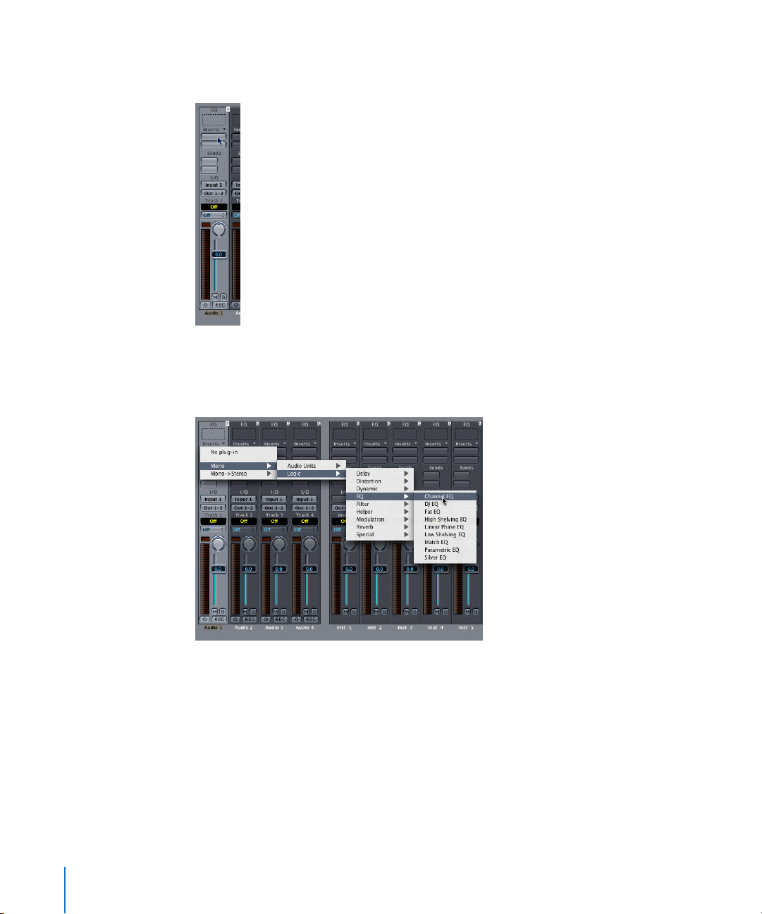
1
Click-hold on an Audio Object’s Insert/Instrument slot.
2
The plug-in-menu appears, showing all available plug-ins. Move the mouse through
the different levels of the hierarchical menu and choose a plug-in name, then release
the mouse button.
The Plug-in window is launched automatically. If you do not want the Plug-in window
to open automatically after insertion, uncheck the
Preferences > Audio > Display > Open
Plug-in window on insertion
preference.
You can open a closed Plug-in window by double-clicking on an assigned Insert/
Instrument slot.
You can set all plug-in parameters in the Plug-in window. For further information
please read “The Plug-in Window” on page 16. Closing the Plug-in window leaves the
plug-in active.
Page 15

Chapter 1
Basics
15
To remove a plug-in:
1
Click-hold the corresponding Insert/Instrument slot.
2
The plug-in menu is opened. Select the
No Plug-In
menu option.
Inserting Mono/Stereo Plug-ins
You can insert mono and stereo effects into Logic’s mono objects. If you use a stereo
effect in a mono object, the plug-in menu is limited to stereo effects from this insert
point onwards.
Note:
In general, stereo effects require twice as much processing power as their mono
counterparts.
In stereo objects, the plug-in menu only shows effects with stereo inputs and stereo
outputs. If you hold the Option key while opening the plug-in menu on stereo objects,
you can also select mono effects.
Logic automatically inserts conversion modules (in the background) to handle stereo
→
mono and mono → stereo transitions. This enables you to use plug-ins in any order.
Please keep the following in mind when doing so:
•
These conversion modules require extra processing power.
•
During a stereo → mono conversion, all spatial information is lost.
•
During a mono → stereo conversion, no spatial information is added—the same
mono signal is sent to both outputs.
Bypassing Plug-ins
If you want to deactivate a plug-in, but don’t want to delete it, you can bypass it.
Bypassed plug-ins do not drain system resources.
To bypass a plug-in:
m
Option-click the appropriate plug-in insert/instrument slot on the desired Audio
Object.
The insert slot of the bypassed plug-in turns from blue to gray, indicating that the plugin is currently bypassed.
You can also use bypass a plug-in from within the Plug-in window. Further information
on this can be found in the following section.
Page 16

16 Chapter 1
Basics
The Plug-in Window
Hands-on operation of plug-ins is performed in the Plug-in window. This window
allows access to all plug-in parameters. The Plug-in window can be opened by doubleclicking on the blue plug-in label on an Audio Object. Each instance of a plug-in has its
own Plug-in window, allowing each to have discrete settings.
Operation of Built-in Plug-ins
Adjusting Parameters
To toggle a Plug-in window’s buttons:
m
Click on the button. It toggles to the next/previous option, or will be enabled/disabled.
To adjust a slider:
m
Click-hold anywhere on the slider and drag up/down or left/right.
To adjust rotary knobs:
m
Click-hold on the center of the rotary knob and drag the mouse up and down. You can
also move the mouse in a circular motion. Fine-tuning of values is easier when using a
larger radius for this circular motion.
To adjust numerical panels:
m
Click-hold on the panel’s numerical value and drag up/down. If there are up/down
arrows alongside such panels, you can use them to increment/decrement the value by
one step.
Note: You can reset any parameter to its default value by Option-clicking on it.
Note: If you hold Shift before clicking and moving a control, its value can be fine-
tuned.
Common Plug-in Window Parameters
The gray area at the top of the Plug-in window is common to all Logic plug-ins. It offers
a number of important functions for plug-in use.
Link
The button to the extreme left (with a chain on it) is called the Link button. If the Link
button is switched on, a single Plug-in window will be used to display all opened plugins. Each time you launch a new plug-in, the window will update to reflect the new
selection. By default, the Link button is switched off, allowing you to open several Plugin windows simultaneously. This is handy if you want to compare the settings of two
plug-ins or adjust several plug-ins at the same time.
Page 17

Chapter 1 Basics 17
When changing the Arrange track, an open Plug-in window will update to display the
corresponding slot’s plug-in on the newly-selected track. As an example, if the ES1 was
loaded on Audio Instrument channel 1, and an EXS24 instance was loaded on Audio
Instrument channel 1, switching between these tracks would automatically update the
Plug-in window to show the ES1/EXS24, respectively.
Bypass
The Bypass button allows a plug-in to be deactivated, but not removed from the insert/
instrument slot. You can also bypass the effect directly in the Audio Object by Optionclicking on the corresponding insert slot.
Settings Menu (Arrow)
Clicking the Arrow to the right of the Bypass button accesses the Settings menu.
Further information on this can be found in “Plug-in Settings” on page 19.
Switching the Contents of the Plug-in Window
You can reassign any open Plug-in window—in two different ways—via the two pull-
down menus to the right of the Settings menu (the Arrow):
• Use the upper pull-down menu (Track 1 in the diagram) to switch the Plug-in
window between all channels that use the same plug-in. If you have inserted the
EVB3 on tracks 1 and 6, for example, you can switch between these channels and
adjust the parameters of each EVB3 instance, respectively.
• In the lower pull-down menu you can switch between the plug-in slots of the
selected channel. As an example, if a particular channel uses an Equalizer and an
EVB3 plug-in, you can switch the Plug-in window between these plug-ins.
Editor—Controls View
The plug-in parameters can be viewed in two forms: Controls and Editor. The Editor
view shows the plug-in’s graphical interface, if it offers one. The Controls view displays
all plug-in functions as a set of horizontal sliders, with numerical fields to the left of
each parameter. These fields are used for both the display and entry of data values.
To switch the view modes:
1 Click-hold the Editor button in the gray area at the top of the Plug-in window.
2 Choose Controls from the pull-down menu.
Page 18

18 Chapter 1 Basics
Some Logic plug-ins may have additional parameters that don’t show up on the Editor
control panel. This is indicated by an additional 001/011 button next to the Link button.
Activate this button to reveal sliders for the extra parameters at the bottom of the Plugin window.
Plug-ins With Side Chain Input
All plug-ins that support side chain inputs, feature an additional Side Chain pull-down
menu in the gray area at the top of the Plug-in window. This facilitates the routing of
any Audio track, Input channel or Bus Object into the plug-in via a side chain.
You can also route an Instrument channel as side chain signal, if you follow
these steps:
1 Create a Send, using a Bus on the Instrument channel.
2 Choose the selected Bus as a Side Chain input for the plug-in.
Once the Side Chain input is selected, the plug-in processes the audio of the channel it
is inserted in, using the trigger impulses provided by the Side Chain. The signal peaks
of the Side Chain input, combined with the Threshold parameter of the plug-in,
determine when the plug-in is triggered.
Examples for Side Chaining
• A sustained pad sound is sent through a noise gate, which is triggered by a drum
track being used as the Side Chain input signal. This results in a rhythmic pad sound
which follows the signal peaks of the drum track.
• A noise gate inserted into a bass guitar channel is triggered by the kick drum track
via the Side Chain. This can “tighten” the timing of the bass guitar, as it follows the
kick drum signal.
• Side Chains can also be used to blend a music mix with a voice-over. To achieve this,
the mix needs to be routed through a compressor which, in turn, is side chained,
using the voice-over track. In this type of setup, the music becomes softer when the
narrator is speaking, and louder, when not. The effect is also known as ducking.
Please note that in order for this to function, the automatic gain make-up or Auto
Gain (if applicable to the compressor plug-in) must be disabled.
Page 19
Chapter 1 Basics 19
Plug-in Settings
Logic’s plug-ins ship with a library of ready-to-play preset sounds, known as Settings.
These Settings can be found in the Logic > Plug-In Settings subfolder, following the
installation procedure.
Note: It is strongly recommended that you do not attempt to change the Logic > Plugin Settings folder structure. Within the Plug-in Settings folder you are, however, free to
sort your settings into sub folders. This folder structure is reflected in a hierarchical
menu, shown each time you load a plug-in setting.
All current plug-in settings are stored with the song file, and are automatically recalled
the next time you load the song. You can also recall and save individual settings via the
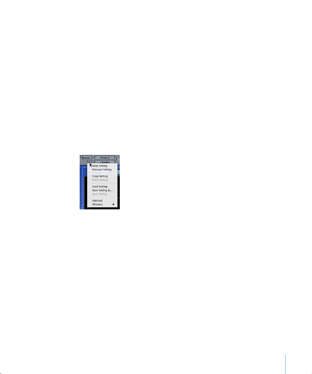
Settings menu functions. The Settings pull-down menu can be opened by clicking on
the Arrow in the gray area at the top of the Plug-in window.
Functions of the Settings Menu
In the gray area at the top of each Plug-in window is an Arrow button. Clicking on it
opens the Settings menu, which features the following functions:
Copy Setting
Choose this entry to copy all parameter settings into a special Settings clipboard, which
is independent from the global Logic clipboard.
Paste Setting
If you have opened a plug-in of the same type (two SilverVerb instances, for example),
you can use this command to paste the parameter set from one to the other via the
Settings clipboard.
Save Setting
This allows you to name and save a setting.
Note: If you save a Setting with the name of #default in a plug-in’s Settings folder, it will
be loaded as the default plug-in Setting.
Page 20

20 Chapter 1 Basics
Load Setting
This function can be used to load a setting. The file selector box only shows settings for
compatible plug-in types. Each plug-in has its own set of parameters, and therefore its
own file format.
Note: Proprietary plug-in-settings created in Logic for Windows can be read by Logic
for Mac OS, and vice versa. Plug-in settings files created on the Mac must be saved with
a .pst file extension in order for them to work in Logic for Windows.
Note: Some plug-ins allow you to load Settings files by dragging and dropping them
from the Finder. This poses a problem as float windows will disappear once Logic is “in
the background”, and the Finder becomes the active application. To circumvent this
issue, you can hold Option when inserting a plug-in, making it a non-floating window.
Next/Previous Setting
These functions allow you to load the next/previous setting in the folder. You can also
make use of the Next/Previous Plug-In Setting (or the Next/Previous Plug-In Setting or EXS
Instrument) key commands. These are not set by default, so you will need to assign
them. Once assigned, you can simply press the appropriate key command to step
forwards/backwards through your plug-in settings. In Logic Pro, Previous/Next Setting
can be assigned to almost any MIDI message, such as Control Change or Program
Change commands.
Settings of other Manufacturers
Logic can read the most common settings files used by Audio Unit plug-ins.
Loading and Saving Multiple Plug-ins
Logic’s Mixer windows allow you to save and load multiple plug-ins (inclusive of their
Settings files) via the arrow pull-down menu alongside the word Inserts on channel
strips. The entire channel strip can be stored and recalled for use on any suitable Audio
Object, allowing common chains of effects such as Reverb, Chorus, and Delay to be
loaded far more quickly than individually inserting each plug-in. Further details can be
found in the Logic reference.
Plug-in Automation
Almost all Logic plug-ins can be fully automated, which means that you can record,
edit, and play back almost any movement of any knob, switch or fader in any plug-in.
For more information, please read the Automation chapter in the Logic reference.
Page 21

Chapter 1 Basics 21
Plug-ins From Other Manufacturers
Audio Unit Support
Correctly installed third-party Audio Unit plug-ins (Effects and Instruments) can be
used in Logic. Clicking on an Audio object insert/instrument slot will launch the
hierarchical Plug-In menu. A separate Audio Units submenu displays all installed Audio
Unit plug-ins.
TDM Plug-ins
Users of a Digidesign TDM system can utilize TDM plug-ins in Logic.
Page 22

Page 23

2
23
2 Instruments and Effects
This chapter explains the difference between effect and
instrument plug-ins.
Instrument plug-ins respond to MIDI note messages, effect plug-ins do not. Therefore
instrument plug-ins can only be inserted into special Audio Objects, called Audio
Instruments.
Effect Plug-ins
Logic’s effects can be installed into all insert slots of all Audio Object types (See
“Inserting and Deleting Plug-ins” on page 13.). This allows processing of all audio and
instrument signals.
There are two ways of sending audio to effects: via an insert, or via a bus (also known
as an “aux send”).
Insert Effects
With insert effects, all of the signal is processed. This means that 100% of the signal
flows through the effect. This is suitable for equalizers or dynamic effects. This also
typically applies to pan knobs and faders.
If you have enough processing capacity, you can use up to 15 insert effects per audio
object. An extra blank insert is created, as soon as all the currently displayed inserts are
used, up to the maximum allowed.
Bus Effects
When you use bus effects, a controlled amount of the signal is sent to the effect. Buses
are typically used for effects that you want to apply to several signals at the same time.
Page 24
24 Chapter 2 Instruments and Effects
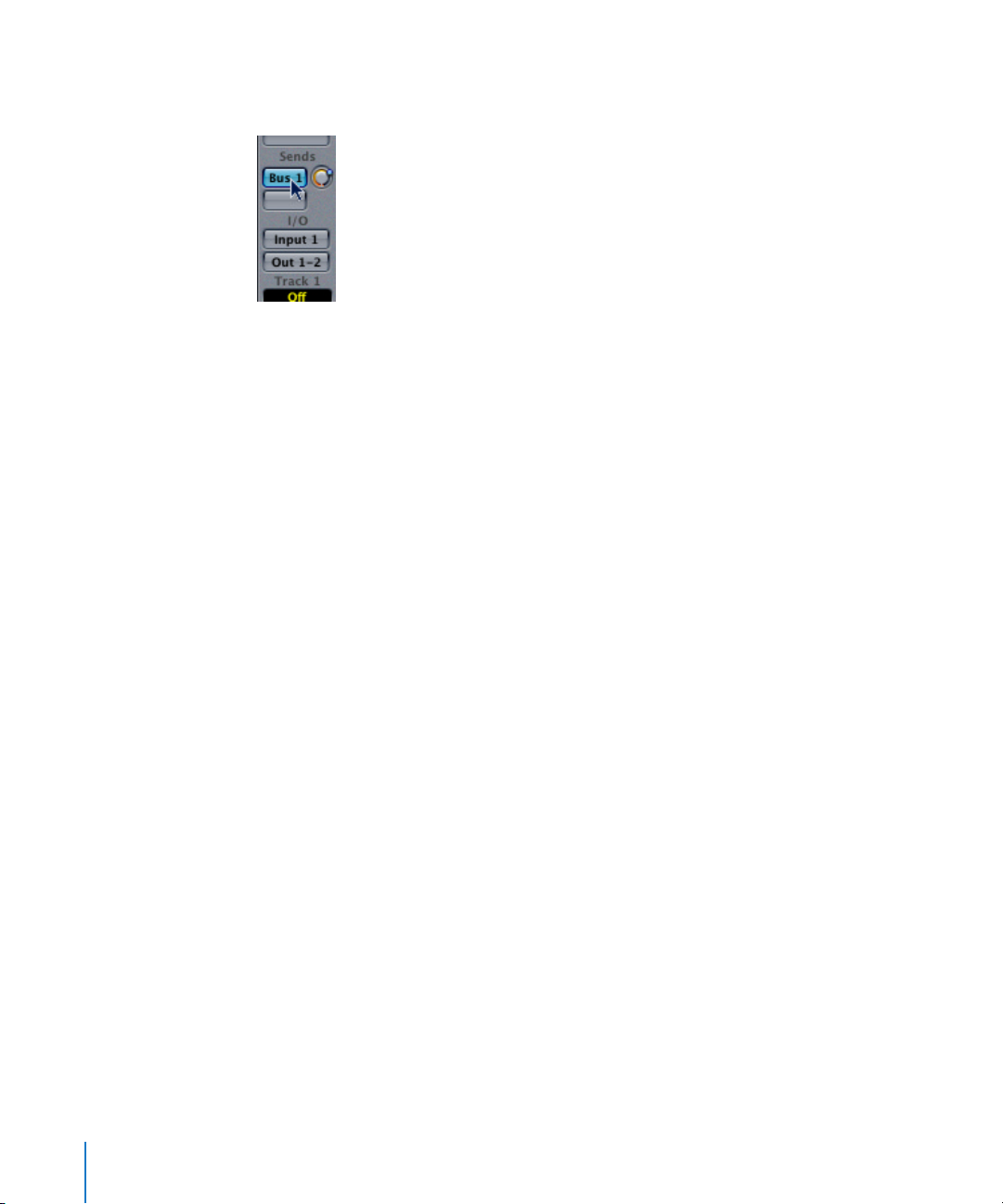
Within Logic, the effect is placed in an insert slot of a bus object. The signals of the
individual tracks can each be sent to the bus, controlled by a Send knob.
The audio signal is then processed with the effect, and mixed with the stereo output.
The advantage of this “bussed” approach, over inserting effects on tracks, is efficiency.
This method allows as many tracks as you like to be processed by one inserted plug-in,
massively saving CPU power when compared to insertion of the same effect directly
into multiple tracks.
For computationally-intensive effects such as reverb, it’s always advisable to insert
them into a bus. Chorus, Flanger, and Delay effects should also always be inserted into
a bus, if they are going to be used on more than one track.
In some cases, it may make sense to patch an effect such as a delay, directly into the
insert of an individual track. There are no restrictions in Logic as to where effects may
be used.
Instrument Plug-ins
The Audio Instrument Object Type
Unlike effect plug-ins, instrument plug-ins respond to MIDI note messages. Instrument
plug-ins can only be inserted into special Audio Objects, called Audio Instruments.
Audio Instruments feature a special instrument slot, directly above their Output slot.
An Audio Instrument is an Audio Object with its Channel parameter switched to one of
the Instruments. Any audio object can be switched to operate as an Audio Instrument,
by changing this parameter (Channel) in the Object Parameter box.
To create an Audio Instrument Object:
1 Open Logic’s Audio Mixer, by choosing Audio > Audio Mixer.
2 In the Audio mixer window select New > Audio Object to create a new Audio Object.
Page 25

Chapter 2 Instruments and Effects 25
3 Double click the newly-created Audio Object icon, so that the (grayed out) channel
strip appears.
4 Now, go to the Object Parameter box, and set the Channel parameter to an Instrument.
The generic Audio Object will now operate as an Audio Instrument, allowing you to
insert any Instrument plug-in into the instrument slot.
The default song—the song that opens if you move the Autoload Song away from the
Logic folder—features a number of ready-configured Instruments, that can be accessed
via the Track Mixer or Audio Mixer.
The output signal of a software instrument plug-in is fed into the input (the instrument
slot) of the Instrument channel strip, where it can be processed via inserted plug-ins
and/or sent to busses.
Logic supports up to 64 discrete Audio Instruments. The number of instrument
instances which can be run simultaneously is dependent on the availability of
computer processing resources.
Following the insertion of an instrument, the Audio Instrument Object can be used just
like a MIDI track in the Arrange window. The Audio Instrument Object can also receive
MIDI notes from standard MIDI instrument objects via Environment cables. This is
useful for creating layered sounds with “real” MIDI instruments and virtual instruments.
Please note that the Options > Preferences > MIDI > Use Unified Virtual and Classic MIDI
Engine setting needs to be switched on for these features to work.
When an Audio Instrument track is selected, it is ready to be played in real-time and
consequently produces some system load. Normally, Logic releases system resources
used by the Audio Engine when the sequencer is stopped. This is not the case,
however, if an Audio Instrument track is selected in the Arrange window, and is
therefore available for real-time playing. Selecting a MIDI track or a standard Audio
track exits this Audio Instrument “stand by” mode, and releases reserved system
resources when the sequencer is stopped.
Note: Muting an Audio Instrument track in the Arrange does not reduce system load.
Page 26
26 Chapter 2 Instruments and Effects
Logic’s Bounce function allows the entire Audio Instrument track to be recorded as an
audio file. This “Bounced” audio file can then be assigned (as an audio region) to a
standard Audio track, allowing you to reassign the available processing (CPU) power for
further synthesizer tracks. For details, please refer to the Bounce chapter in the Logic
Reference manual.
You can also make use of the Freeze function to capture the output of an Audio
Instrument track, again saving processing power. For details please refer to the Freeze
section, in the Logic Reference manual.
Accessing Multiple Outputs
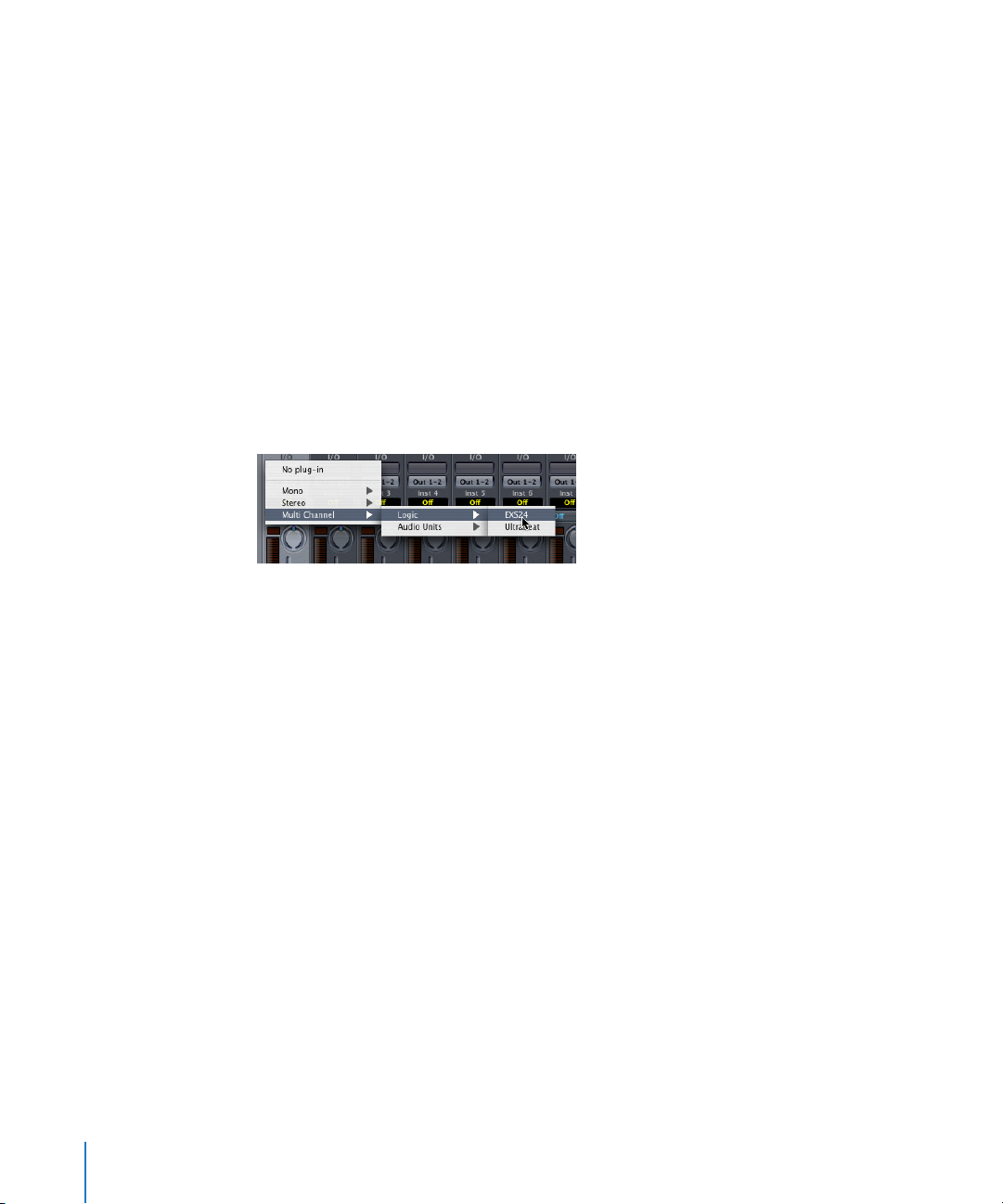
Logic supports the multiple outputs of the EXS24 and all Audio Unit (AU) compatible
instruments. In addition to the Mono and Stereo submenus of the Audio Instrument
plug-in menu, a Multi Channel submenu lists all Instruments that offer multiple outputs.
A plug-in needs to be inserted from the Multi Channel submenu, in order to access its
individual outputs.
Note: Not all plug-ins (both Logic and third-party) are multi-output capable. If the
Instrument does not appear in the Multi Channel submenu, it is not equipped with
multiple output facilities.
The first two outputs of a multiple output instrument are always played back as a
stereo pair by the Instrument channel in which the plug-in is inserted. Additional
outputs (3 and 4, 5, and 6, and so on) are accessed via the Aux Objects.
Page 27
Chapter 2 Instruments and Effects 27
Software Instrument Pitch
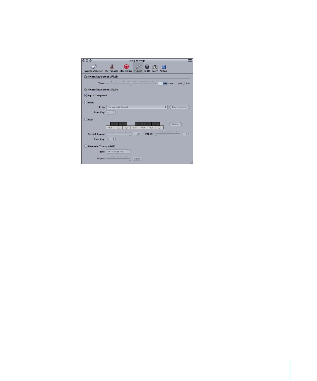
The Song Settings > Tuning > Software Instrument Pitch > Tune parameter remotely
controls the main tuning parameter for all software instruments (plug-in synthesizers,
such as the ES1 or EXS24 sampler and others) by ±100 cents.
Note: Some instruments do not recognize this remote command.
No Hermode Tuning
Logic allows all software instruments to be globally tuned to different tempered scales,
including Hermode Tuning (see the Tuning section of the Logic reference manual for
details). There may, however, be occasions where you want individual Software
Instruments to be exempt from this global tuning system.
When File > Song Settings > Tuning > Hermode Tuning is active, a No HMT checkbox is
visible in the Object Parameter boxes of all Audio Instrument channels. Simply click in
this box to prevent the selected software instrument from following the global
Hermode Tuning scale.
Any software instrument with an active No HMT checkbox will be played back at equal
temperament.
Page 28

Page 29
3
29
3 Equalizer
This chapter covers all Logic equalization effects.
Equalizers allow you to increase or decrease the level of
selected components in the overall audio spectrum.
Logic’s built-in equalizers include the Channel EQ, Linear Phase EQ, Match EQ, Fat EQ,
Silver EQ, DJ EQ, High/Low Pass Filters, High/Low Cut EQ, Parametric EQ and High/Low
Shelving EQ plug-ins.
Channel EQ
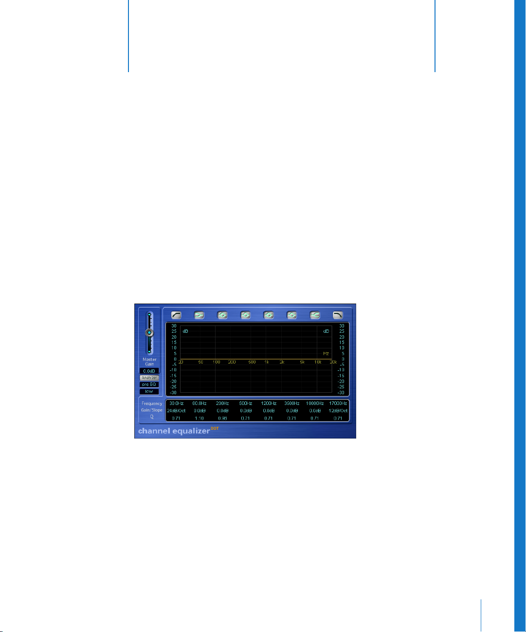
The extremely high-quality Channel EQ offers eight frequency bands and an
integrated FFT analyzer.
EQ Parameters
The Band Type buttons above the display activate the Channel EQ’s bands individually;
inactive bands do not use any computer resources.
Band 1 is a lowpass filter and band 8 is a highpass filter.
Note: The Q-parameter of band 1 and band 8will have no effect when using a slope of
6 dB/Oct.
Page 30

30 Chapter 3 Equalizer
Bands 2 and 7 are defined as shelving equalizers.
Note: When the Q parameter of band 2 and 7 is set to an extremely high value (to 100,
for example), the equalizers only apply to a very narrow band, and can work in a
fashion that is similar to notch filters.
Bands 3to 6 are bandpass filters.
You can set the band parameters either in the parameter area or directly in the central
EQ display. Move the mouse horizontally over the display. When your mouse cursor is in
the access area of a band, its individual curve and parameter area will be highlighted
and a pivot point appears. When you click-hold the mouse button directly on the
(illuminated) pivot point of a band, vertical movements (up/down) will change its Q
value. Horizontal movements (left/right) change the Frequency of the band. When you
click-hold the mouse button on the display background, horizontal movements will
again change the Frequency of the band. Vertical mouse movements will change the
Gain of band 2 to 7. The slope values of the highpass and lowpass filters (bands 1 and
8) can only be changed in the parameter area below the graphic display. Click-hold on
the parameter: Moving up increases, and down decreases, the value.
After boosting or cutting frequency bands, you can use the Master Gain fader to
readjust the output level of the Channel EQ.
Channel EQ—Analyzer
The precision analyzer of the Channel EQ uses Fast Fourier Transformation (FFT) to
show the energy of all frequency components of the signal. The central display of the
Channel EQ fulfills multiple display functions: it shows both the curve of the FFT
analyzer and the EQ curve. An identically scaled frequency axis is shown for both. This
allows you to easily recognize unwanted frequencies in the analyzer curve, while using
the EQ to edit them accordingly.
A click on the Analyzer button activates/deactivates the FFT analyzer. The display
directly under the button determines the location of the Analyzer. You can switch the
Analyzer pre EQ or post EQ (default) in order to compare the original signal with your
edits.
Click into the display to open a pull-down menu that defines the resolution of the FFT
analyzer—or more accurately, the number of frequency bands. The higher the precision
of measurements, the more CPU power is needed.
High resolutions are necessary whenever you need reliable results in the very low bass
frequency area. The bands derived from FFT analysis are divided in accordance with the
frequency linear principle—non-technically, this means that there are far more bands
in the highest octave than in the lowest.
Page 31

Chapter 3 Equalizer 31
Use the Scales to the left and right of the EQ display, to change the vertical scale of the
EQ and analyzer curves.
To increase the resolution of the EQ Gain parameter (dB Warp) in the most interesting
area around the zero line, click-hold in the green dB Scale on the left side of the
graphic display, and move the mouse up. Moving the mouse down, will decrease the
parameter value. The overall range is always ±30, but small values will be easier to
recognize.
As soon as the Analyzer is activated, you can change the Analyzer Top parameter, which
alters the scaling of the FFT analyzer, on the right side of the graphic display. The visible
area represents a dynamic range of 60 dB, but by click-holding and vertically dragging,
you can adjust the maximum value between +20 dB and −40 dB. The Analyzer display
is always dB-linear.
Two additional Analyzer parameters are available via the 001/100 view. Analyzer Mode
allows you to switch between Peak and RMS. Analyzer Decay allows you to adjust the
decay rate (in dB per second) of the Analyzer curve (peak decay in Peak mode or an
averaged decay in RMS mode)
Note: The FFT analyzer needs additional CPU resources. In fact, resource consumption
increases significantly at higher resolutions! We recommend that you disable the
Analyzer or close the Channel EQ window after setting the desired EQ parameters. This
will free up CPU resources for other tasks.
Using the Channel EQ as the Default EQ
The Channel EQ replaces the Track EQ of older Logic versions. It is inserted into the first
available insert slot by double-clicking the EQ area on the upper portion of mixer
channel strips. This area will change to a thumbnail view of the Channel EQ display. The
thumbnails provide an overview of the EQ settings used in each individual channel.
Page 32
32 Chapter 3 Equalizer
Linear Phase EQ
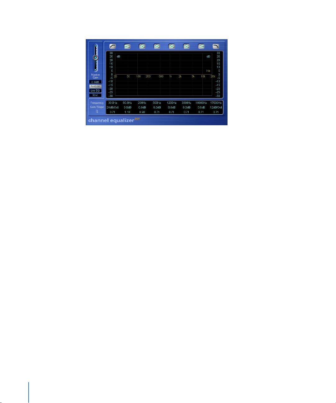
The extremely high-quality Linear Phase EQ plug-in is almost identical to the Channel
EQ. With the exception of the different name and a few different colors, it uses the
same familiar eight-band layout, and method of operation, as the Channel EQ.
Under-the-hood, however, the Linear Phase EQ uses completely different technology
which preserves the phase of the audio signal 100%—even if the wildest EQ curves are
applied to the sharpest signal transients!
As with all good things in life, there is a catch. The Linear Phase EQ uses more CPU
power than the Channel EQ. Another factor is the inherent amount of latency
introduced by this technology. Logic’s plug-in delay compensation will successfully
prevent the worst of these latency artefacts in mixdown situations—but don’t even
think about playing software instruments live when using the Linear Phase EQ.
As the parameters of the Channel EQ and Linear Phase EQ are almost identical, you
may freely copy settings between them. For more information on the parameters of
the Linear Phase EQ, read up on the “Channel EQ” on page 29.
Page 33
Chapter 3 Equalizer 33
Match EQ
The Match EQ plug-in allows you to “match”, and transfer the frequency spectrum from
one signal to another, or to store it as a spectral template file. In this way, you can
acoustically match the sound of various songs for an album, or impart the “sound” of
any reference source onto your own recordings. The alignment of signals is automatic,
but you can also manually draw or modify the filter curve to alter the sound as
required.
Note: Match EQ acoustically matches two audio signals. It does not, however, match
any dynamic differences in the two signals.
Description of the basic functions
Match EQ is a learning equalizer that reads the frequency spectrum of any reference
source, including: the input signal, an audio file, or a template. Alternatively, you can
load a setting file or import the settings of another Match EQ instance via a copy and
paste operation.
You can analyze the average audio spectrum of the track the plug-in is assigned to or
load another setting file or template. By matching both spectra, a filter curve is
generated. This generated curve adapts the track signal to match the sound of the
template. If required, you can modify the filter curve by boosting or cutting gain in
different frequencies, or inverting it. Further to this, you can manually modify the curve
by creating a virtually infinite number of peak filters, and adjust them as required. In
this way, you can draw your own filter curve to optimize the sound as required. The
internal analyzer allows you to visually check the frequency spectrum of the original
data and the resulting curve, making manual corrections at specific points within the
spectrum easier.
Page 34

34 Chapter 3 Equalizer
Parameters
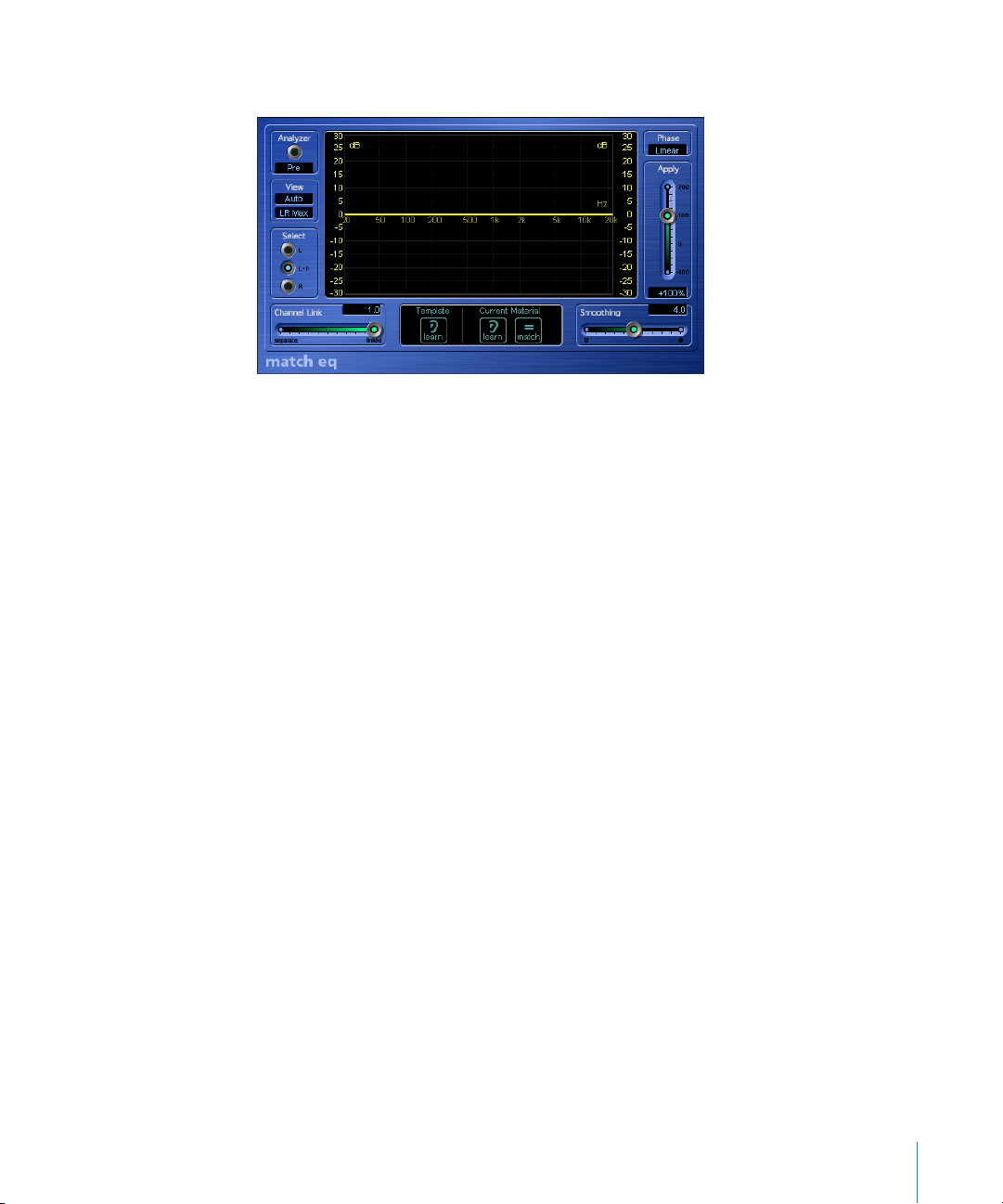
The View pull-down menu allows you to select the type of information shown on the
analyzer display in the center. The following options are available:
• Automatic: Depending on the selected function, the analyzer view is automatically
toggled between the three following options.
• Template: The analyzer display shows the average frequency curve, which is
generated by analyzing the input signal or loading a template.
• Current Material: The analyzer visualizes the average frequency curve, which is
generated by analyzing the track signal or loading a Setting file or template.
• Filter: The analyzer displays the filter curve, which is generated by matching the
Template and the spectra of the Current Material.
Independent of the selection, the analyzer can be activated/deactivated via the On/Off
button. The Analyzer Position pull-down menu allows you to place the analyzer tap
before (Pre: unchanged) or behind the filter circuit (Post: behind the Match EQ).
Note: Deactivating the analyzer frees up processing power for other applications.
On stereo channels, the view mode is configured via the lower View toggle menu. You
can select whether the analyzer displays both audio channels via separate curves (L&R)
or the summed maximum level (LR Max).
You can manually modify the filter curve generated via matching the Template with the
Current Material. The buttons in the Select section let you choose whether the
modifications are applied only to the left, right, or both channels.
You can refine this selection via the Channel Link slider. If the slider is set to 1.0, the L
and R buttons for the single channels will have no effect, because both channels are
represented via a common EQ curve. At the minimum value of 0.0, two separate filter
curves are displayed, each of which can be selected for editing via the L and R buttons.
The intermediate settings of the Channel Link slider allow you to blend these extreme
values as required. As a result, any modification to either of the filter curves is
transferred to both channels, dependent on the Channel Link setting.
Note: In the mono version of the plug-in, the parameters in the View Mode, Select, and
Channel Link sections have no effect.
The Template and Current Material buttons perform the spectral analysis of the audio
signals, and match the resulting curves. Clicking the Learn button in the Template
section starts and stops measurement of the average frequency spectrum in the
reference signal.
Clicking the Learn button in the Current Material section starts and stops measurement
of the average frequency spectrum in the audio material of the track.
Page 35

Chapter 3 Equalizer 35
Note: Audio files can also be dragged onto the Template or Current Material Learn
buttons to generate template or current spectra. A progress bar displays the progress
of the analysis process.
If you right-click (or Control click) on either of the Learn buttons, a context menu opens.
This menu allows the spectrum of the template or the track signal (Current Material) to
be:
• cleared
• copied to the Match EQ clipboard, which is common to all Match EQ instances in the
current song.
• pasted from the Match EQ clipboard to the active instance.
• loaded from a stored Setting file.
• generated from an audio file (chosen in the File Selector). This is done by choosing
the Generate Template/Current Material Spectrum from audio file option, and selecting
an appropriate file in the file selector that appears. A progress bar displays the status
of the analysis process.
Note: When you activate the Learn button in either the Template or Current Material
section, the View parameter is set to Auto, and the analyzer will display the current
status of the spectral analysis, indicated by a progress bar.
The Match button in the Current Material section allows you to write the differences
between the learned or loaded Template and the learned or loaded spectrum of the
Current Material to a filter curve. Differences in gain are automatically compensated for,
with the resulting EQ curve referenced to the 0 dB line.
The filter curve is updated automatically each time a new template or current material
spectrum is learned or loaded, when the Match button is enabled. You can toggle
between the matched (and possibly scaled and/or manually modified) filter curve and
a flat response by activating/deactivating the Match button.
Note: Each time a new audio spectrum is matched—either by loading/learning a new
spectrum while Match is activated or by activating Match after a new spectrum has
been loaded—existing manual modifications are discarded, and Apply is set to 100%.
Basically, only one of the Learn buttons may be active at a time. As an example, if the
Learn button in the Template section is active and you press the Learn button in the
Current Material section, the analysis of the template file stops, and the current status is
used as the spectral template. Analysis of the track (Current Material) will then begin.
Note: If you have manually modified the filter curve, the original (or flat) curve can be
restored by Option-clicking on the background of the analyzer display. A second
Option-click restores the most recently modified curve.
Page 36

36 Chapter 3 Equalizer
The filter curve can be edited via the Smoothing slider. At a value of 0.0, the filter curve
is applied to the track signal without any changes. At all other Smoothing settings, the
filters are smoothed at a constant bandwidth. A value of 1.0, for example, means that all
filters have a constant bandwidth of one semitone that is used to smooth the notchlike filters in the curve. A bandwidth of: four semitones (a value of 4.0—or a major
third), an octave (a value of 12.0) and two octaves with the maximum setting (24.0).
Note: Smoothing does not affect any manual modifications of the filter curve.
The Apply slider exaggerates (101% to 200%), reduces (99% to 1%) or inverts the peaks/
dips (−1% to −100%) the effect of the filter curve on the track signal. At a value of 100%,
the signal is aligned to the curve without any changes.
The Phase toggle menu switches the operational principle of the filter curve.
• The Linear option prevents processing from altering the signal phase. At the same
time, the latency of the plug-in will increase.
• The Minimal option alters the signal phase, but latency is reduced.
Manual Modifications
You can graphically edit the matched filter curve directly in the display. Just click at any
point within the filter curve to create a new peak band. You can shift the peak
frequency for this band (within the entire spectrum) by dragging the mouse
horizontally. Vertically moving the mouse allows you to set the gain of this frequency
band (range: −24 to +24 dB). The Q-factor of the filter is set by the vertical distance
between the click point and the curve. By clicking on the curve, the maximum Q-value
of 10 (for notch-like filters) is used. Clicking above or below the curve decreases the Qvalue. The further you click from the curve, the smaller the value (down to the
minimum of 0.3).
• The Q -factor can be changed continuously by pressing Shift and moving the mouse
up/down while keeping the mouse button pressed.
• If Option is hold while releasing the mouse button, the modification is cancelled.
Note: The current values are shown in a window within the display while the left
mouse button is held down.
The colors and modes of the dB scales on the left and right of the display are
automatically adapted to the active function. If the analyzer is active, the left scale
displays the average spectrum in the signal, while the right scale serves as a reference
for the peak values of the analyzer. Basically, the analyzer visualizes a dynamic range of
60 dB. The displayed range can, however, be shifted between the extreme values of
+20 dB and −100 dB by click-dragging on the scale.
Page 37
Chapter 3 Equalizer 37
If the resulting filter curve is displayed, the left scale—and the right, if the analyzer is
inactive—shows the dB values for the filter curve in an appropriate color. By clickdragging on one of the scales, the overall gain of the filter curve is adjusted in the
range from −30 to +30 dB.
Fat EQ
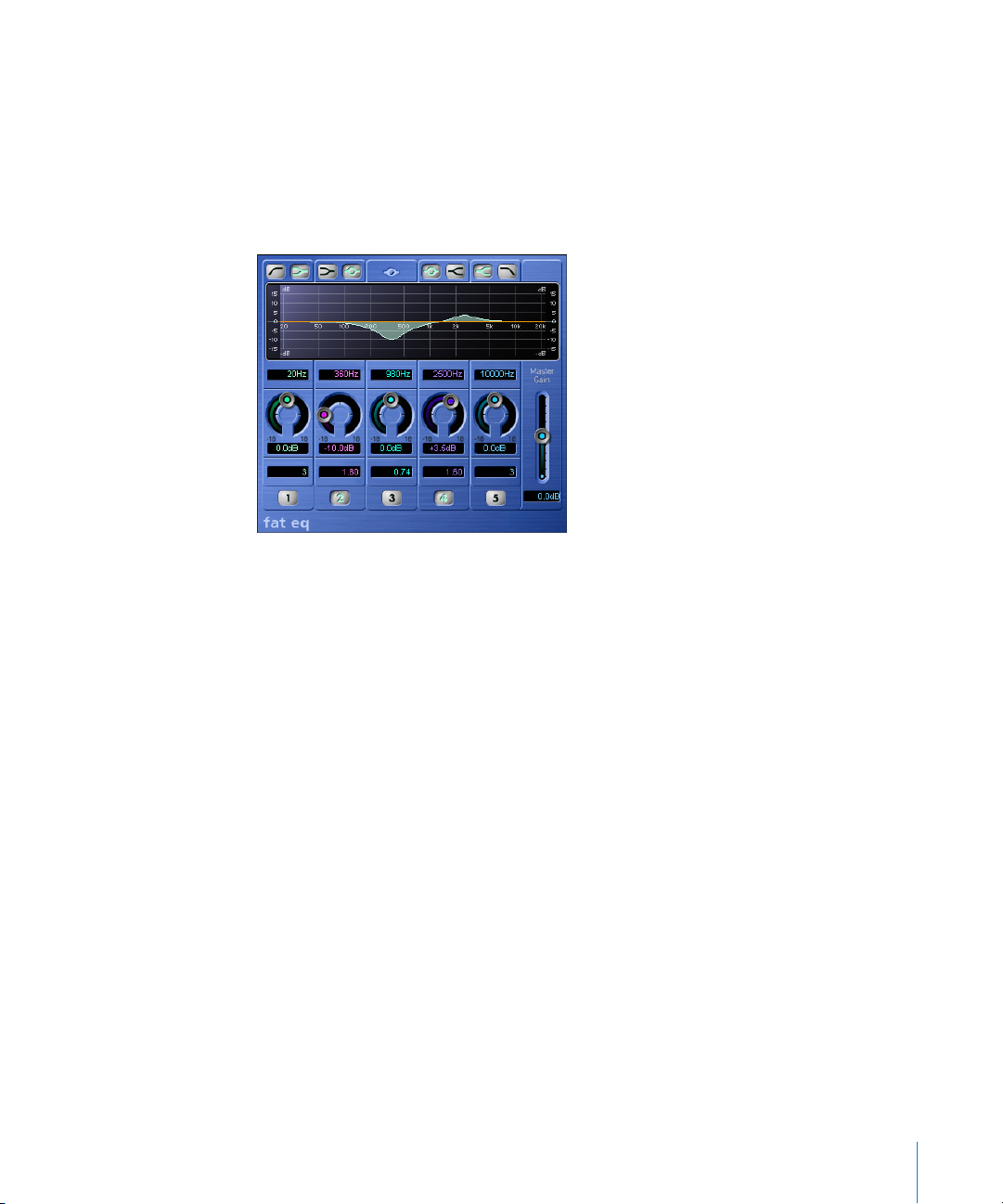
The high-quality Fat EQ offers up to 5 fully parametric bands—buttons 1 through 5
activate these individually; inactive bands do not drain your computer’s resources.
The icons above the graphic display let you determine whether Band 1 acts like a
highpass filter or a low shelving EQ. Similarly, Band 5 can be switched back and forth
between use as a lowpass filter and a high shelving EQ. Bands 2 and 4 can be switched
from their normal operating mode (as fully parametric bandpass filters) to low or high
shelving EQs. The center band (number 3) always operates as a fully parametric
bandpass filter. The shelving filter’s slope characteristics for bands 2 and 4 are
adjustable via the Q parameter.
The area directly below the graphic display (depicting the frequency response curve) is
used to select the frequency for the individual bands. Simply click on the number, and
change the value with your mouse. You’ll be able to hear an individual frequency better
if you turn it up by rotating the Cut/Boost knob located below it clockwise.
The same holds true for any frequency that you want to attenuate. Once you’ve located
the frequency that you’re hunting for, you can back off the Cut/Boost knob level, and
set it to the desired value. Use the Q (bandwidth) parameter located in the lower
display to determine the extent that the band influences neighboring frequencies.
Page 38

38 Chapter 3 Equalizer
At low Q values, the EQ influences a wider frequency range, and at high Q values, the
effect of the EQ band is limited to a very narrow frequency range. Please bear in mind
that your perception of an attenuated or boosted frequency depends heavily on the Q
parameter: If you’re working with a narrow frequency band, you’ll generally need to
cut or boost it more drastically to notice a difference.
Silver EQ
The Silver EQ contains one High Shelf, a Parametric and one Low Shelf filter with the
corresponding parameters. More on each of these is found in the Individual EQ’s
section below.
DJ EQ
The DJ EQ combines Low and High Shelving Filters with a fixed frequency, and one
Parametric EQ with its attendant parameters. More on each of these is found in the
Individual EQ’s section below.
The special feature of the DJ EQ is that it allows the gain of the filters to be reduced
down to −30 dB.
Individual EQs
Parametric EQ
The Parametric EQ offers the following three parameters:
• Hz: Center frequency
• dB: Cut/Boost
• Q: Quality
A symmetrical frequency range on either side of the center frequency is boosted or cut.
You can adjust the width of this frequency range with the Q control.
High Shelving EQ/Low Shelving EQ
• The Low Shelving Equalizer only affects the frequency range below the selected
frequency.
• The High Shelving Equalizer only affects the frequency range above the selected
frequency.
Page 39
4
39
4 Dynamic
This chapter introduces Logic’s Dynamic plug-ins.
This includes the Compressor, Silver Compressor, Expander, Noise Gate, Silver Gate,
Enveloper, DeEsser, Limiter, Multipressor, and Adaptive Limiter plug-ins.
Compressor
A compressor tightens up the dynamics of a signal. This means that the difference in
levels between loud and soft passages is reduced. This “evening out” of the loud and
soft passages means that the peak level remains pretty constant, and the overall
loudness—the perceived volume—of a track is increased. Next to an EQ, a compressor
is your most valuable sound-shaping tool when mixing. A compressor is a universal
effect, it has a virtually unlimited range of applications. You should definitely exploit it
for vocal tracks, but a compressor can also often work wonders for entire mixes. When
you use a compressor, be sure to route the entire signal through it, by inserting it
directly into channels. It should only be used in a bus when you want to compress a
group of tracks (a drum kit, for example) simultaneously, and by the same amount.
Again, these tracks (individual drums in a kit, for example) should be routed to the bus
in their entirety, as opposed to using Send knobs to route just parts of each signal to
the bus. You do this by selecting the appropriate bus as the output destination for the
tracks that you wish to compress.
Page 40

40 Chapter 4 Dynamic
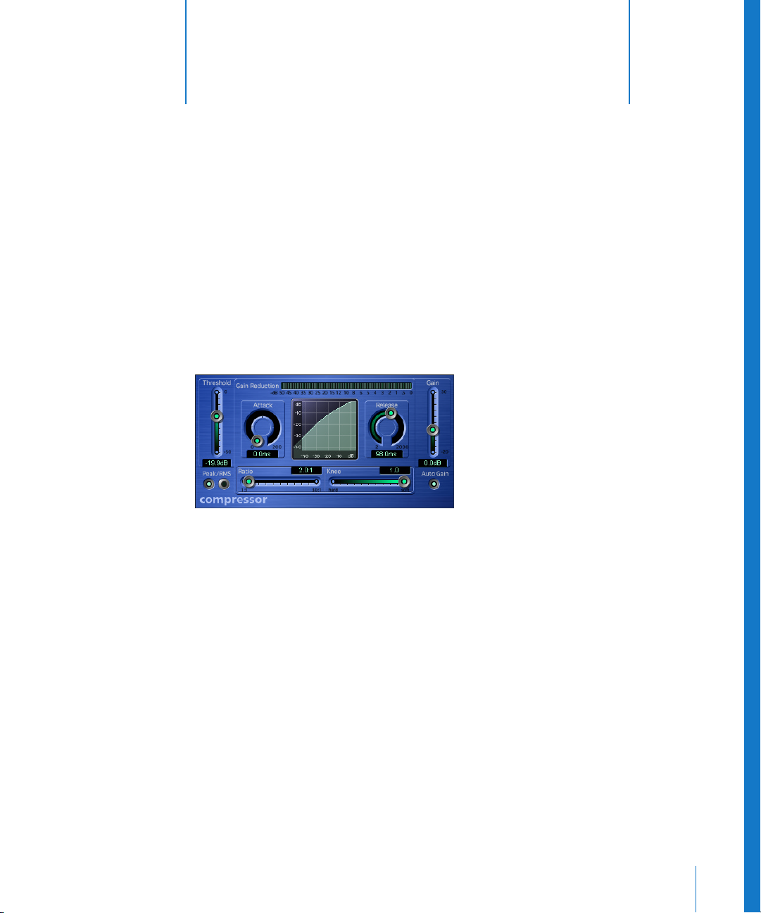
Logic’s Compressor was designed to emulate the response of the finest analog
compressors. It follows the following principle: When a signal exceeds the defined
Threshold level, the compressor actually alters the response, so that it is no longer
linear. What happens is that all levels that exceed the Threshold are attenuated by the
value set with the Ratio slider. A ratio of 4:1 means that an incoming level that is 4 dB
louder than the Threshold level is dampened, so that it comes out the other end of the
compressor with a level that is just 1 dB above the Threshold level. On the flip side, if
you route in a signal that is loud enough to double the output level of the compressor
(+6 dB), the input signal would need to have a level 24 dB greater than the Threshold
level. This tells us that a compression ratio of 4:1 is a fairly drastic manipulation of the
original signal’s dynamics. Given that the compressor lowers levels, the volume of its
output signal is normally lower than that of the input signal.
To compensate for this decrease in levels, the output of the compressor is equipped
with a Gain slider. Auto Gain automatically sets the level of amplification to a value
equivalent to the “sum of the threshold value minus the threshold value divided by the
ratio” or put less confusingly T—(T/R). This function ensures that a normalized input
signal is amplified so that the output signal is also normalized, regardless of the values
set for Threshold and Ratio—provided you are dealing with relatively static signals. Use
the Attack and Release knobs to shape the dynamic response of the compressor. Attack
determines the amount of time it takes for the compressor to react to signals that
exceed the Threshold. At higher values, the compressor does not fully dampen a signal
until it runs through its Attack phase. This type of setting ensures the original attack, for
example the sound of a pick or finger striking a guitar string, remains intact or clearly
audible. If, on the other hand, you want to maximize the level of a master signal, set the
Attack knob to low values, ensuring that the compressor responds more swiftly. Release
determines the amount of time it takes for the compressor to stop dampening louder
passages, once the signal level falls below the Threshold level. If the compressor
generates an ugly pumping sound, adjust the Release knob accordingly.
Page 41

Chapter 4 Dynamic 41
When you have configured a compressor so that it dampens the signal at or above the
Threshold value by the predetermined Ratio, while the level just below the Threshold is
routed through at a 1:1 Ratio, an audio engineer would term the compression as hard
knee. In many cases, however, you’ll come up with a better sounding track by using a
more gradual transition from the 1:1 Ratio below the Threshold, to the Ratio that you
entered for levels above the Threshold. In this scenario, the characteristic curve is not as
radical—it rises gradually from the bottom left to the top right, as seen in the graphic
display. This type of compression is called soft knee. The Knee slider lets you
incrementally select anything from hard to soft knee. This wide range of options
provides you with the tools you need to shape the sound as you like; whether you
want to radically maximize loudness with absolutely no regard for the original
dynamics (hard), or are going for the more musical compression that acoustic
recordings typically require (soft). Keep in mind that Knee only controls the shape of
the compression, not its intensity; use the Threshold and Ratio sliders for this purpose.
Incidentally, the Gain Reduction Meter indicates the intensity of compression used to
tighten up the original signal. This feature is a great help, particularly if you’re not
experienced with using compression. Keep an eye on it to make sure that you’re not
overly compressing your tracks.
When the compressor has to decide whether or not the level exceeds the Threshold (or
if the level is getting close to the Threshold, for soft knee compression), it can analyze
either the peak or RMS level. The latter value is a better indication of how humans
perceive loudness. When you use the compressor primarily as a limiter, select the Peak
button. When you’re compressing individual signals, use of the RMS button will often
deliver better, more musical results.
If you activate Auto Gain and RMS simultaneously, the signal may be saturated. If you
hear any distortion, switch Auto Gain off, and enter a suitable gain level manually.
The Output Clip parameter limits (clips) the output to 0 dB, via the OFF/SOFT/HARD
settings. This setting is only available in the Controls view.
Note: Despite all of these handy tips for tweaking sounds, you should always keep one
thing in mind—there are no hard and fast rules. Use your own taste and ears. If it
sounds good, it is good.
Page 42
42 Chapter 4 Dynamic
Silver Compressor
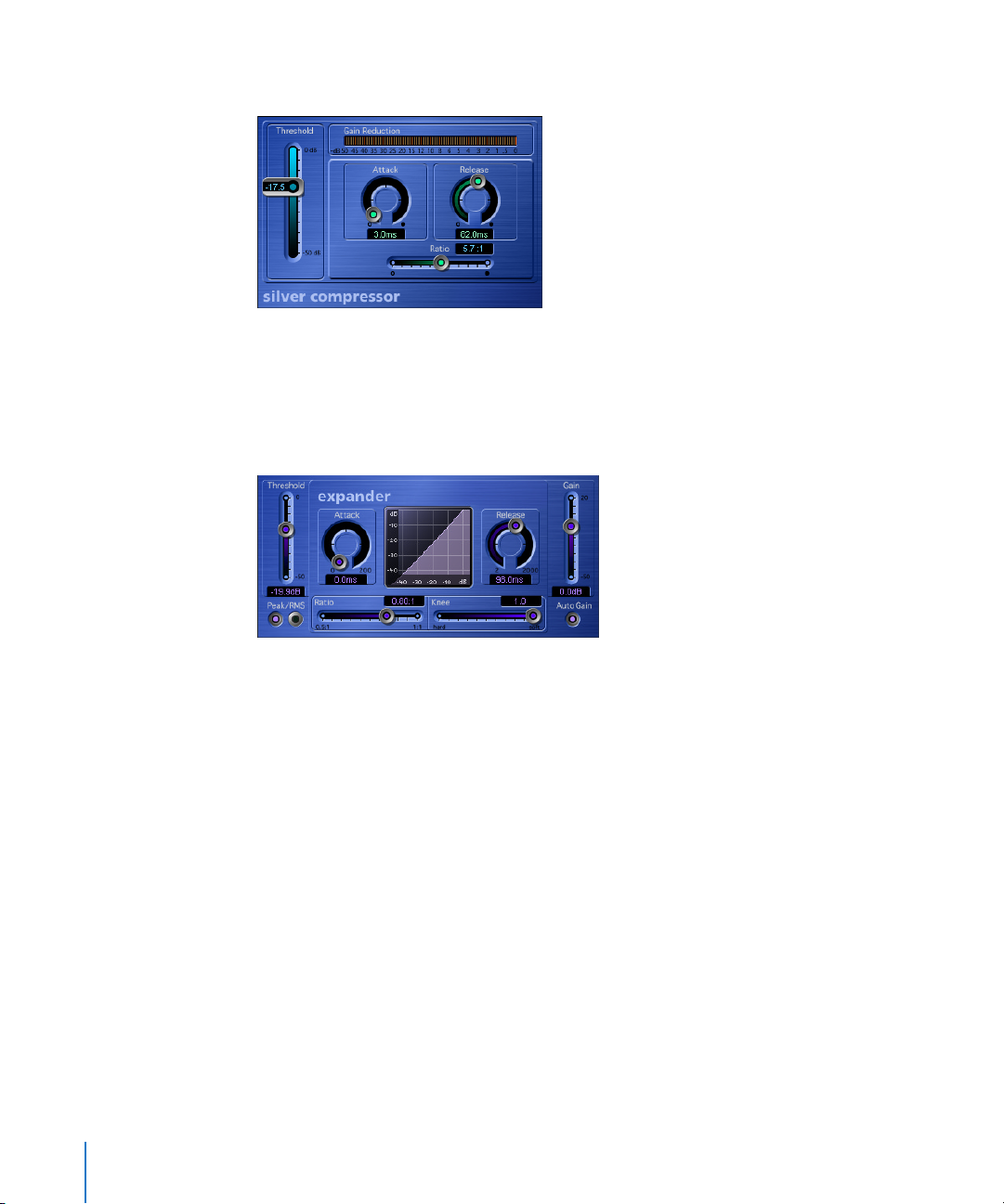
The Silver Compressor is a simplified version of the Compressor. It is limited to
Threshold, Attack, Release, and Ratio controls.
Expander
The Expander is similar to the Compressor, with one fundamental difference—it
increases, rather than reduces, the dynamic range above the Threshold.
The Ratio slider features a value range of 1:1 to 0.5:1. This means that the Expander is a
genuine upward expander (as opposed to a downward expander that increases the
dynamic range below the Threshold). You can use this effect to emphasize the
transients of highly compressed signals. This spices up the sonic image, making it
sound livelier and fresher.
Please bear in mind the fact that you will perceive the signal as being softer, even
when the peak level remains the same. In other words, the expander decreases
loudness. If you manipulate the dynamics of a signal fairly radically (depending on the
Threshold and Ratio values), you’ll find that you’ll need to reduce the level via the Gain
slider to avoid distortion. In most cases, Auto Gain will take care of this for you.
Please check the Compressor section for details on the various parameters.
Page 43
Chapter 4 Dynamic 43
Noise Gate
Ordinarily, a noise gate suppresses unwanted noise that may become audible during a
lull in the signal. You can, however, also use it as a creative sound-sculpting tool.
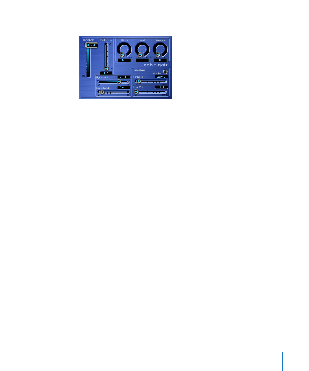
Here’s the basic principle behind a noise gate: Signals that lie above the Threshold are
allowed to pass unimpeded (open gate). Anything below the defined Threshold
(background noise, crosstalk from other signal sources and so on) is fully muted (a
closed gate). In other words, the Threshold slider determines the lowest level that a
signal must be at, in order to open the gate—it separates the wanted or useful signal,
from the unwanted or noise signal.
The Reduction slider allows you to control the intensity of noise suppression. As a rule,
you should set it to the lowest possible value and leave it there, to ensure that the gate
closes completely. If you prefer, you can select other values, thus reducing the noise
signal less dramatically. As an alternative, you can actually boost the signal by up to
20 dB.
The three rotary knobs (at the top) influence the dynamic response of the noise gate. If
you want the gate to open extremely quickly, say for percussive signals such as drums,
set the Attack knob to the lowest value by turning it as far as it will go counterclockwise. If the signal fades in a bit more softly, as is the case with string pads and the
like, a noise gate that opens too quickly can wreak havoc with the signal, causing it to
sound unnatural.
For this type of sonic scenario, set the Attack knob so that the gate emulates the attack
of the original signal. Much the same holds true for the Release phase of signals. When
you’re working with signals that fade out gradually or have longer reverb tails, you
should turn the Release knob up, allowing the signal to fade naturally.
The Hold knob determines the minimum amount of time that the gate stays open. This
knob avoids the dreaded chattering effect caused by a rapidly opening and closing
noise gate. The Hysteresis slider provides another option for avoiding chatter, without
needing to define a minimum Hold time.
Page 44

44 Chapter 4 Dynamic
Let’s back up a bit for a brief explanation: Noise gates often begin chattering when the
level of a signal fluctuates slightly, but very rapidly, during the attack or release phase.
Instead of clearly exceeding or falling short of the Threshold value, the signal level
hovers around the Threshold. The Noise Gate then rapidly switches on and off to
compensate, producing the undesirable chattering effect. If you were able to tell the
Noise Gate to open at the determined Threshold level and remain open until the level
drops below another, lower, predefined Threshold level, you’d be able to avoid
chatter—as long as the sonic window formed by these two Threshold values is large
enough to contain the fluctuating level of the incoming signal.
This is exactly what the Hysteresis feature enables you to do—the value determined by
the Hysteresis slider is actually the difference between the Threshold values that open
and close the gate. This value is always negative. Generally, −6 dB is a good place to
start.
If you’re dealing with audio material featuring extremely sensitive transients, or attack
phases that are critical to the overall sound, you may find it beneficial to have the Noise
Gate open up a tad before the useful signal fades in. This is what the Lookahead slider
is designed for. The program analyzes the signal level ahead of time, and anticipates
the point at which it can open the gate before the signal actually reaches the Threshold
value. When you choose to use this feature, please make sure you set the Attack, Hold
or Hysteresis controls to appropriate values.
When you’re working with noise gates, you’ll run across scenarios where the useful
signal and the noise signal have levels that are near enough to be perceived as
identical. A typical example is the crosstalk of a hi-hat—its signal tends to bleed into
the snare drum track when you’re recording a drum kit. If you’re using a noise gate to
isolate the snare, you’ll find that the hi-hat will also open the gate in many cases. To
avoid this effect, the Noise Gate offers Side Chain filters.
When you press and hold the Monitor button, you can audition the Side Chain signal.
You can then set the filters to only allow frequencies that contain a particularly loud,
useful signal to pass. For this example, we’ll use the Noise Gate’s High Cut filter—that
only allows the bottom end and mids of the snare to pass, and cuts the higher
frequencies of the hi-hat. When you switch Side Chain Monitoring off, it will be much
easier to set a suitable Threshold level. This will be a value that is only exceeded by the
level of the louder useful signal—the frequencies that make up the snare’s
fundamental tone, in our example. Put simply, the Noise Gate only allows the sound of
the snare to pass. Should the need arise, you can follow much the same procedure to
isolate a kick or snare drum within an entire mixdown.
Page 45
Chapter 4 Dynamic 45
Silver Gate
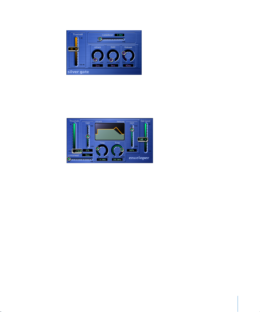
The Silver Gate is a cut-down version of the Noise Gate. It is limited to Threshold,
Lookahead, Attack, Hold, and Release controls.
Enveloper
The Enveloper is an unusual tool that lets you shape transients—the attack and release
phases of signals. No other type of dynamic effect (such as a compressor or expander)
can achieve similar results—and these results can be quite impressive indeed.
The most important Enveloper controls are the two Gain sliders that govern Attack (left)
and Release (right). In the center position, the signal remains unprocessed. If you turn
the gain up, the attack or release phase is emphasized. If you turn it down, the
corresponding phase is attenuated. As an example, boosting the attack lends a drum
sound more snap, or amplifies the sound of a guitar string being plucked or picked.
When you cut the attack, percussive signals fade in more softly. You can also mute the
attack, making it virtually inaudible. This facilitates a range of interesting manipulations.
Another handy application for this plug-in is maintaining friendships—it allows you to
mask the poor timing of accompanying instruments, rather than tell your pals that they
“groove like a bunch of accountants at the office Christmas party”.
Page 46

46 Chapter 4 Dynamic
Emphasizing the release also boosts the amount of any reverb on the affected track.
Conversely, when you tone down the release phase, tracks originally drenched in
reverb end up sounding drier. This effect is particularly useful when you’re working
with drumloops, but there are, of course, many other applications. Let your imagination
be your guide.
When using the Enveloper, you should set the Threshold to the minimum value and
leave it there. Only when you seriously crank the release phase, thus boosting the noise
level of the original recording, should you turn the Threshold slider up a little. This limits
the Enveloper to only influencing the useful signal.
Drastic boosting or cutting of the release or attack phase may change the overall level
of the signal. The Out Level slider allows you to compensate for this effect.
The Time parameters for the attack and release phase (2 knobs below the graphic
display) enable you to access the time-based intervals that the plug-in interprets as the
attack and release phases. Generally, you’ll find values of around 20 ms (attack) and
1500 ms (release) are fine to start with. Adjust them accordingly for the type of signal
that you’re processing.
Similar to its Noise Gate counterpart, the Lookahead slider allows you to define values
that tell the Enveloper to anticipate what the signal will do in the very near future.
Normally, you won’t need to use this feature, except possibly for signals with extremely
sensitive transients. If you do decide to use Lookahead, you may need to adjust the
attack time accordingly.
To give you a better insight into the true nature of the Enveloper, here’s a quick look at
how it works: It is equipped with two internal envelope followers. One follows the
amplitude of the input signal directly, whereas the other follows all changes generated
by the variable delays (individually adjustable for attack and release). The difference
between the two envelope followers is used to boost or cut the original signal by way
of the corresponding Gain sliders (also individually adjustable for attack and release).
In contrast to a compressor or expander, the Enveloper operates independently of the
absolute level of the input signal—provided the Threshold slider is set to the lowest
possible value.
Page 47
Chapter 4 Dynamic 47
DeEsser
A DeEsser is a signal processor used for the rejection of hissing, or sibilant noises. This is
why it is called a “DeEsser”, and occasionally an “S”-Suppressor. You can, of course, reject
sizzling frequencies with an equalizer, but a DeEsser only rejects this high frequency
band for as long as a threshold level is being exceeded in a specific frequency band.
This “dynamic” ability is why the sound doesn’t get darker when no “sizzling”
consonants are present in the signal. A DeEsser is a frequency-specific compressor,
designed to only compress a particular frequency band within a complex full band
signal. It features extremely fast attack and release times.
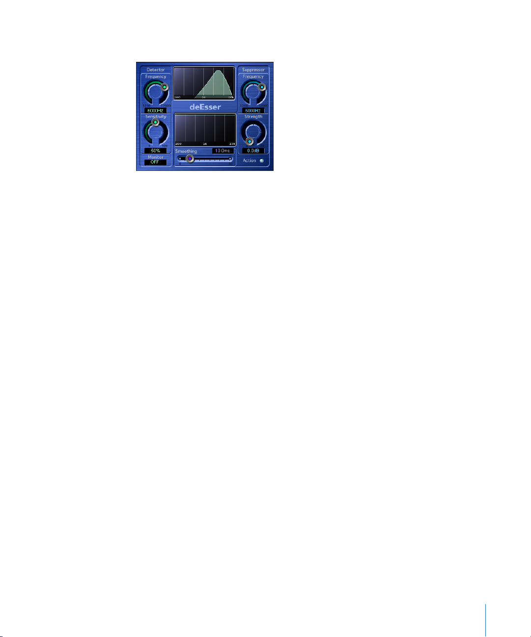
In the Logic DeEsser, the dynamic rejection does not necessarily need to take place in
the same frequency range that’s being analyzed. Rather, the DeEsser performs a gain
reduction in the frequency band displayed in the lower window for as long as the level
exceeds a threshold (which falls within the frequency range) displayed in the upper
window.
Note: Please don’t confuse a DeEsser with an effect known as a “Vocal Stressor”. The
latter reduces the gain of the entire range when the level exceeds a threshold defined
in a given frequency range. This type of processing can be achieved with any
compressor with a high pass filter or EQ inserted in its side chain.
The Logic DeEsser does not make use of a frequency dividing network (a crossover,
utilizing low and high pass filters). Rather, it is based on a subtraction of the isolated
frequency band, leaving the phase-curve untouched.
The DeEsser is especially important in FM radio applications, because sharp S-type
consonants can cause harsh intermodulation distortion noises. The need for this
depends very much on the language spoken: English has fewer of these consonants
than German or Spanish, for example.
Page 48

48 Chapter 4 Dynamic
Parameters of the DeEsser
Detector Frequency
This parameter defines the frequency band the DeEsser acts upon. It’s not necessarily
the same band that will be reduced.
Detector Sensitivity
This parameter defines the threshold level that needs to be exceeded (around the
Detector Frequency), in order to reduce the level around the Suppressor Frequency.
Monitor
Activation of this switch allows you to monitor the Side Chain signal used by the
DeEsser. If you want to reduce sizzling noises, listen to the input signal, and set the
Detector Frequency in a way that makes the sizzling frequency range more prominent.
(If you find that you like this filtered sound, combine a highpass and lowpass filter—in
order to construct a bandpass—as this approach uses less processing power).
Suppressor Frequency
This parameter defines the frequency band that is reduced when the Detector
Frequency Sensitivity threshold is exceeded.
Strength
Strength sets the amount of gain reduction around the Suppressor Frequency.
Smoothing
Smoothing controls the reaction speed of the gain reduction start and end phases. It’s
a combination of attack and release time parameters, as known from compressors.
Page 49
Chapter 4 Dynamic 49
Limiter
The Limiter is also a standard effect for processing a summed stereo signal. It is
normally used for mastering.
You could say that a limiter is a compressor with an infinite compression ratio. The
Limiter restricts dynamics to an absolute level. Any input level that exceeds the
Limiter’s threshold (Gain) will be output at this “limited” level, no matter how much
higher the original signal level may have been. The fact that there is a level that the
signal cannot exceed is the distinguishing characteristic of a limiter, when compared to
a compressor.
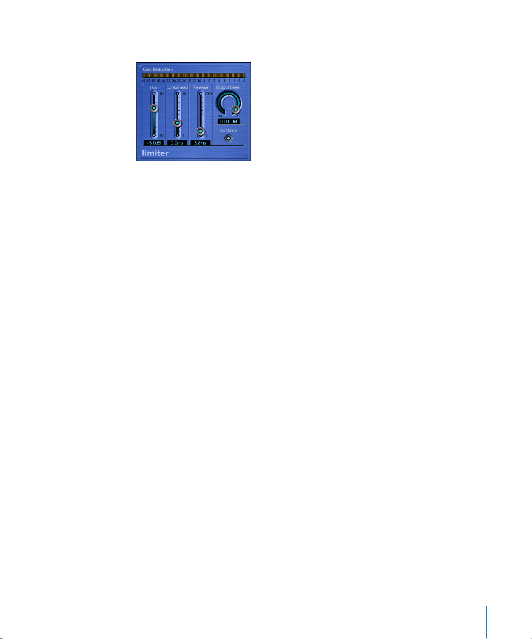
Parameters of the Limiter
Gain
Most analog limiters would have a “Threshold” control (like that of the Multipressor),
rather than a “Gain” control. This sets the level at which the Limiter will begin to work.
As the Limiter is digital, and is normally is applied as the very last mastering tool, we
can presuppose that:
• the input signal sometimes reaches 0 dB, but does not exceed this value, and
• that the Limiter is being used to raise the signal’s overall volume. This is the reason
why you find a Gain control here—to set the desired level of gain for the signal.
The Limiter is designed in such a way that if set to 0 dB Gain and 0 dB Output Level, it
doesn’t work at all—on normalized regions. If there should be a region that clips (red
gain line), the Limiter—using its basic settings—reduces the level before clipping can
occur. (This does not apply to data that was clipped during recording).
Lookahead
Lookahead determines how far the processor looks into the future, in order to react
earlier (thus better) to peak volumes. Unlike stand-alone processors, this function does
not apply a general signal delay, as the Limiter is not limited to seeing the signal in
real-time.
Set Lookahead to higher values, if you want the limiting effect to take place before the
maximum level is reached.
Page 50
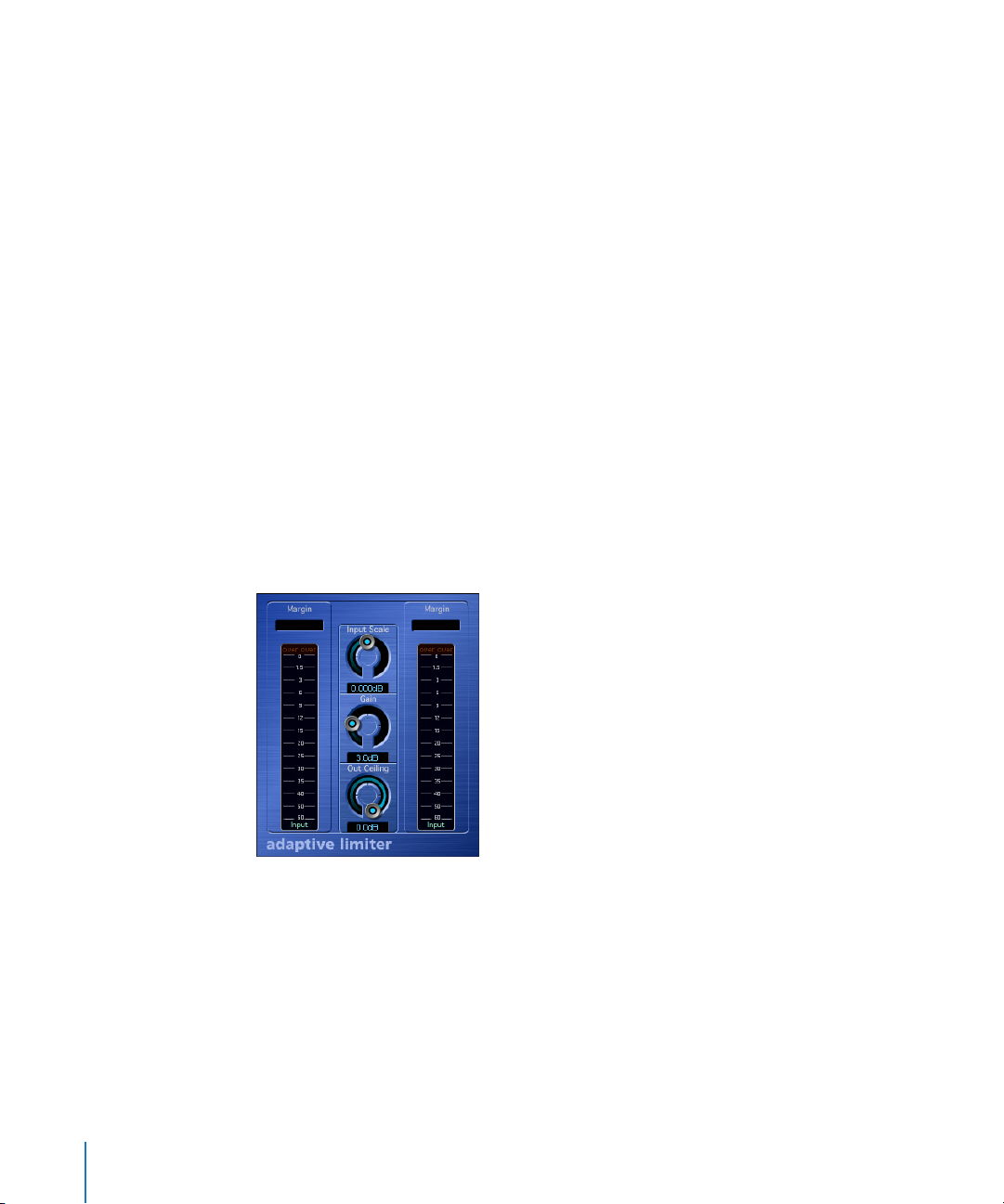
50 Chapter 4 Dynamic
Release
Here, you can set the time required by the Limiter (after limiting) to release the effect.
Output Level
This simple volume control sets the desired maximum level of the Limiter’s output
signal.
Softknee
Activate the Softknee button to produce a softer transition from no limiting to full
limiting.
If switched off, the signal will be limited (following a linear curve) absolutely and
exactly when a level of 0 dB is reached.
If switched on, the transition to full limiting is non-linear, meaning softer. The limiting
of the signal will start before a level of 0 dB is reached. This will avoid distortion
artefacts occurring when strong limiting is used without softknee.
Graphic Display
The graphic display shows the reduction of the level (starting from 0 dB downwards).
Adaptive Limiter
With its Compressor (see “Compressor” on page 39), Multipressor (see “Multipressor” on
page 52) and Limiter (see “Limiter” on page 49) Logic features several extremely
versatile options for increasing perceived volumes. A further tool which can be used to
increase the perceived level of signals is the Adaptive Limiter plug-in. In the world of
analog processors, it could be more closely compared to a clipper, rounding and
smoothing only harsh level peaks, rather than to a VCA-type limiter. It allows you to
achieve maximum gain, without having to fear exceeding 0 dBFS. The Adaptive Limiter
may slightly color the sound. An effect most similar to an amplifier when driven hard.
Page 51

Chapter 4 Dynamic 51
Following the Adaptive Limiter process, tracks normalized to 0 dB appear to sound
about 2 dB louder, depending on the source signal. As with other Logic dynamic
processes, this plug-in also features a lookahead facility (the Lookahead parameter can
be set in Controls view, allowing the Adaptive Limiter to look into the future. The
Adaptive Limiter reacts to level peaks in signals streaming from the hard disk before
they are played back, and delaying the monitored signal. The typical use of the
Adaptive Limiter is in the summed mix. It is placed after the Multipressor and before
Gain, in order to produce a CD of maximum loudness. As the Adaptive Limiter
compresses signals, it can produce results which sound louder than those resulting
from normalizing in the Sample Editor.
Start the process by adjusting the Input Scale, just as you would set a mixing desk’s
Gain parameter, or a digital recorder’s recording level. The parameter behaves much
like a Gain control, but its purpose is to adjust the input level, which must never exceed
0 dBFS. Adjust the Gain parameter to musically control the internal process of peak
smoothing and gain increase.
Out Ceiling reduces the output level of the process in very fine steps within a range of
only 2 dB. This is no threshold control, just a simple output gain.
The Mode menu in the Adaptive Limiter’s Controls view allows you to choose between
two different forms of peak smoothing. If you choose:
• OptFit, the signal will be limited by following a linear curve. This form of peak
smoothing allows signal peaks that exceed 0 dB.
• NoOver ensures that the signal never surpasses 0 dB, avoiding distortion artefacts.
Remove DC (Controls view) activates a highpass filter that removes direct current from
the signal. When using poorly constructed audio hardware, direct current (DC) can be
undesirably layered over the audio signal.
The Margin display shows the maximum measured level. To reset, click the Over lamps.
Page 52
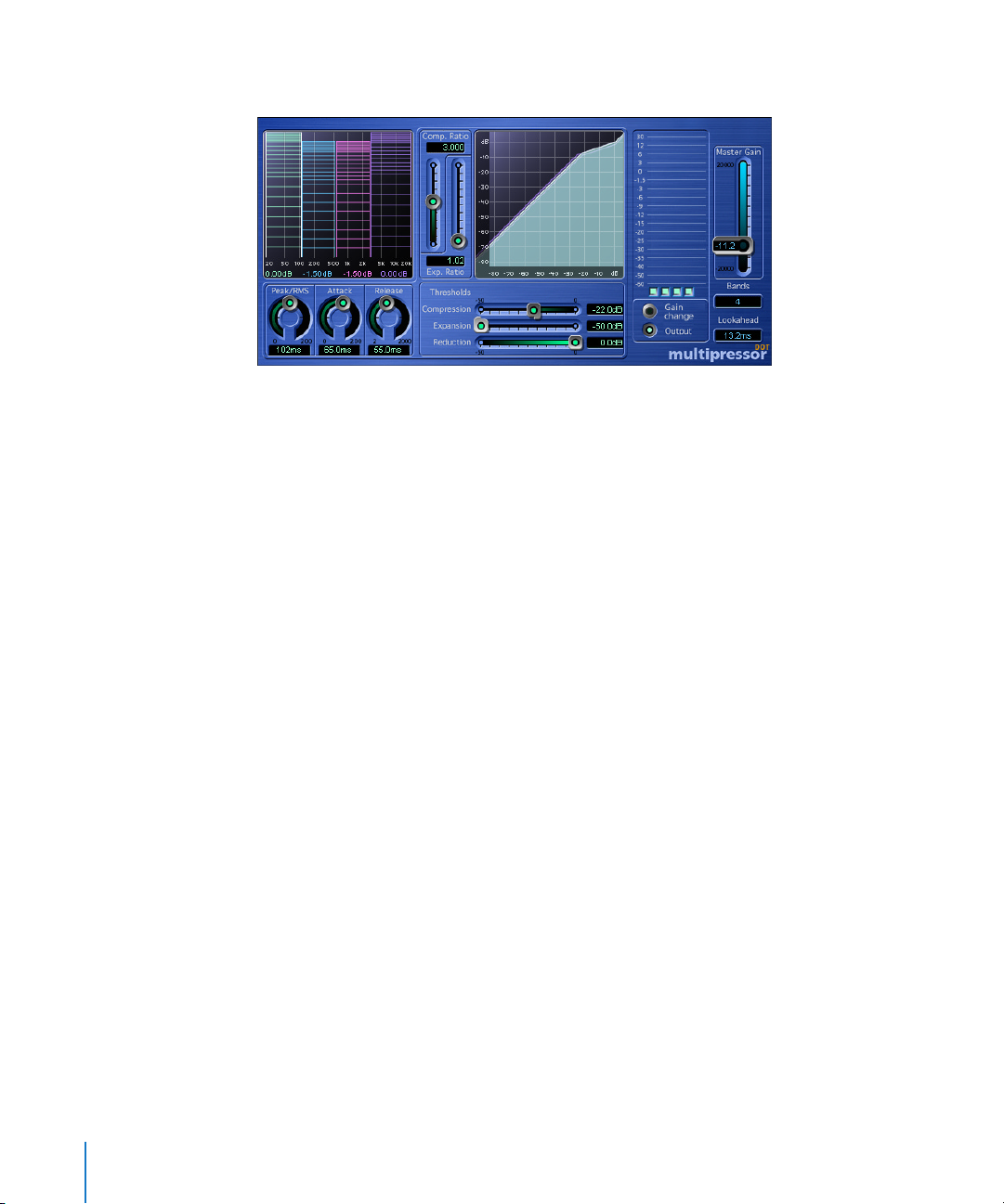
52 Chapter 4 Dynamic
Multipressor
The Multipressor (an abbreviation for multiband compressor) is the epitome of an
audio mastering tool. It’s a pretty complex tool; good sounding settings require quite a
lot of listening experience.
Functional Principle of Multi-band Compressors
The multi-band compressor splits the incoming signal into two to four different
frequency bands before applying compression. These frequency bands are then
compressed independently. After compression, the frequency bands are mixed back
together.
The aim of independent compression of different frequency bands is to reach high
compression levels on the bands that need it, without the pumping effect that is
normally heard at high compression levels.
Much higher Ratios, and therefore, a much higher average volume is possible before
the unwanted artefacts of compression will be heard.
Downward Expansion
Strong multi-band compression allows you to raise the overall volume level—resulting
in a dramatic increase of the existing noise floor. Downward expansion allows you to
reduce or suppress this noise. Each frequency band features a downward expander.
This works as the exact counterpart to the compressor: while the compressor
compresses the dynamic range of the higher volume levels, the downward expander
expands the dynamic range of the lower volume levels. With downward expansion, the
signal will be reduced in level when it is lower than the defined Threshold level. The
effect can be compared to a noise gate, but rather than simply cutting off the sound, it
smoothly fades the volume using an adjustable Ratio.
Page 53

Chapter 4 Dynamic 53
Multipressor Parameters
Bands
This parameter (on the right side) determines the number of independently
compressible frequency bands, and has a crucial impact on the amount of computing
power needed for the effect. Classic multi-band compressors use three Bands.
Lookahead
Lookahead (just below the Bands parameter) determines how far the processor looks
into the future, in order to react earlier (thus better) to peak volumes.
Set Lookahead to higher values, when the Peak/RMS control (see below) is set further
towards RMS.
Peak/RMS
Adjusting the control between Peak (full left) and RMS (Root Meantime Square; full
right) is dependent on the type of signal you would like to compress. An extremely
short Peak detection setting is suitable for compression of short and high peaks of low
power, which do not typically occur in music. The RMS detection method measures the
power of the audio material over time and thus works much more musically. This is
because human hearing is more responsive to the overall power of the signal than to
single peaks. As a basic setting for most applications, the centered position is
recommended.
Attack
Allows you to define the time (in milliseconds) required before compression is faded in.
Release
Sets the time required by the compressor (after compression) to release the effect. Just
as with the other values, the best setting for this parameter depends greatly on the
material to be compressed.
Multi-band Graphic
The graphic editor to the left of the Multipressor displays several settings, both
graphically and numerically.
• Crossover Frequencies
The crossover frequencies (vertical borders) between the bands are variable. To
change a band’s crossover point, grab the borders directly within the graphic and
move them to the left or to the right. The frequency is displayed numerically at the
bottom of the graphic.
• Absolute Volume
The horizontal line in the middle of each band displays its current level
(default: 0 dB). By grabbing the area below this line and moving it up and down, you
can set the absolute volume level of the corresponding band. The level is displayed
numerically at the bottom of the graphic. This ability allows the Multipressor to serve
as a basic equalization tool, dependent on how the crossover frequencies are set.
Page 54

54 Chapter 4 Dynamic
• Threshold Display
The horizontal lines (up to three) in the lower area of the window represent the
Threshold values for Compression (upper line), Expansion (middle line), and
Reduction (bottom line). You can set these values by using the controls of the same
name (see below).
Note: You can select the frequency band that you wish to edit by clicking in the lower
section of each band.
Comp. Ratio
This, in conjunction with Compression Threshold, is the central parameter for
compression. The Comp. Ratio determines the strength or rate of level reduction in the
range you want to compress. In most cases, the most useful combinations of these two
settings are either 1) low Compression Threshold and low Comp. Ratio or 2) high
Compression Threshold and high Comp. Ratio.
Exp. Ratio
This, in conjunction with Expansion Threshold, is the central parameter for controlling
downward expansion. It determines the strength of expansion applicable to the range
that you wish to expand.
Graphic Curve
The graphic curve in the middle of the Multipressor shows the Ratio between input
level (horizontal scale) and output level (vertical scale) of all bands. The colors
correspond to the colors of the frequency bands in the left graphic area. Adjustments
to the Ratio and Threshold controls allow you to change the curvature of the selected
frequency band.
Thresholds
• Compression
Here, you can set the minimum level at which the compressor will begin to work. If
the control is set all the way to the right (0 dB), the entire compressor section of the
Multipressor is off-line. The further you move the control to the left, the lower the
level above which the compressor will work.
• Expansion
Here, you can set the maximum level at which the expander should work. If the
control is set all the way to the left (−50 dB), expansion will only occur on signals that
fall below this level. (The Exp. Ratio can be set to a minimum of 1,2:1; below −50 dB
the expansion always takes place at this low ratio.) The further the control is moved
to the right, the higher the level below which the expander will work.
Reduction
Allows you to define the amount of noise level reduction (this is not a threshold value).
If you move the control all the way to the left, the reduction will be at its maximum
value (−50 dB). If the control is set all the way to the right, no reduction will occur.
Page 55

Chapter 4 Dynamic 55
Level Meter
In the Level Meter to the right, you may monitor either; the change of level caused by
compression, or the output volume of each band, depending on whether you have
selected Gain change or Output (see below). You can individually switch the bands on
and off, in order to listen to single bands, by using the switches below the meters. If the
switch below a band’s meter is lit (light green), the band will be audible. If a switch is
unlit, the band is muted.
Gain Change/Output
The Gain change and Output buttons can be used to switch the operating mode of the
meters.
• If Gain change is selected, the meters indicate the strength of level reduction (to the
audio material) by the compressor.
• If Output is selected, the meters show the absolute output level of the corresponding
frequency band.
Master Gain
Allows you to reduce the overall gain increase (or increase the overall gain reduction),
resulting from the Multipressor’s settings.
Page 56

Page 57
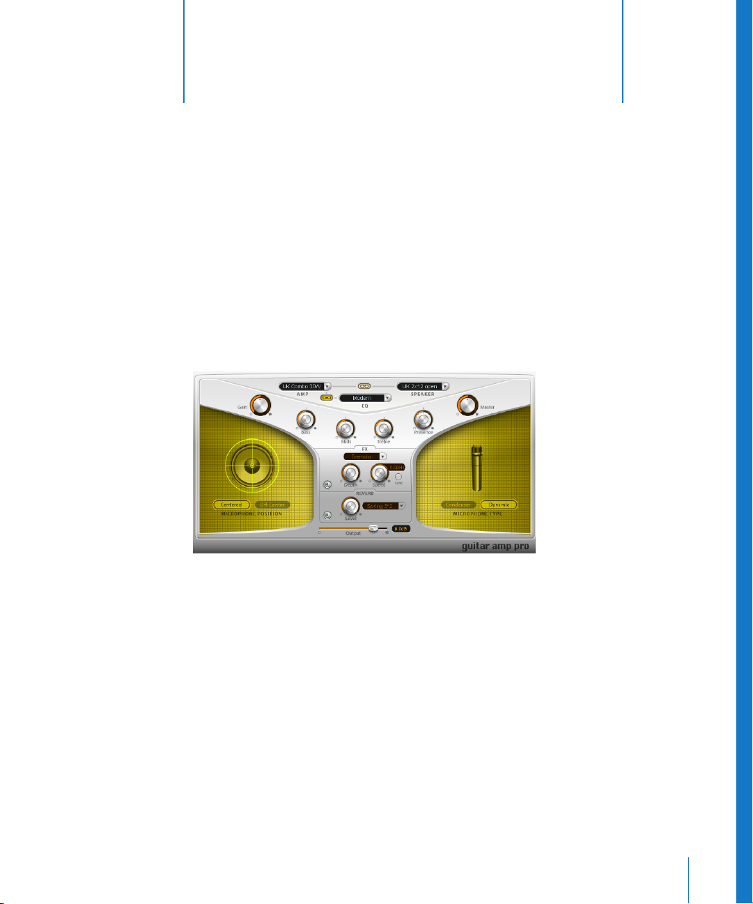
5
57
5 Distortion
This chapter introduces you to Logic’s distortion effects.
This includes the Distortion, Overdrive, Bitcrusher, Clip Distortion, Phase Distortion,
Distortion II, and Guitar Amp effect plug-ins.
Guitar Amp Pro
The Guitar Amp Pro plug-in simulates the sound of several famous guitar amplifiers
and a number of cabinets/speakers. You can process guitar signals directly within Logic,
allowing you to reproduce the sound of high-quality guitar amplification systems.
Guitar Amp Pro can also be used for experimental sound design and processing. You
can freely use the plug-in on other instruments, as desired—applying the sonic
character of a guitar amp to a trumpet or vocal part, for example!
Guitar Amp Pro offers a range of Amplifier, Speaker, and EQ models that can be
combined in a number of ways. The EQ models are equipped with the Bass, Mid, and
Treble controls typical of guitar amplifiers. Miking can be switched between two
different microphone types and positions. To round out the complement of controls,
Guitar Amp Pro also integrates two classic guitar effects, namely Vibrato and Tremolo.
Page 58

58 Chapter 5 Distortion
The Guitar Amp Pro panel is divided into three areas. The upper part of the raised Yshaped user interface contains the Amplifier parameters section. The bottom of this
panel houses the Effect and Output section of the plug-in. The Speaker sections to the
left and right provide access to the miking parameters of the virtual speaker.
Amp Section
In the upper area of the Amp section, you will find three pull-down menus. These allow
you to set up your guitar amp as required, by selecting the appropriate Amp, Speaker,
and EQ model(s).
Eleven different amplifier models can be accessed via the Amp menu to the left.
• UK Combo 30W—neutral sounding Amp model, well suited for clean or crunchy
rhythm parts.
• UK Top 50W—quite aggressive in the high frequency range, well suited for classical
rock sounds.
• US Combo 40W—clean sounding Amp model, well suited for funk and jazz sounds.
• US Hot Combo 40W—emphasizes the high mids of the frequency range, making this
model ideal for solo sounds.
• US Hot Top 100W—this Amp model creates very fat sounds, even low Master settings
result in broad sounds with a lot of “oomph”.
• Custom 50W—with the Presence parameter set to 0, this Amp model is well suited for
smooth fusion lead sounds.
• British Clean—simulates the classic British Class A combos which have been
continuously produced since the 1960s to the present, without any significant
modification. This model is ideally suited for clean or crunchy rhythm parts.
• British Gain—reproduces the sound of a British tube head, and is synonymous with
rocking, powerful rhythm parts and lead guitars with a rich sustain.
• American Clean—emulates the traditional full tube combos used for clean and
crunchy sounds.
• American Gain—emulates a modern Hi-Gain head, making it suitable for distorted
rhythm and lead parts.
• Clean Tube Amp—emulates a tube amp model with very low gain (distortion only
when using very high input levels or Gain/Master settings).
The Speaker menu at the top right provides access to 15 speaker models.
• UK 1×12 open back—Classic open enclosure with one 12" speaker, neutral, well-
balanced, multifunctional.
• UK 2×12 open back—Classic open enclosure with two 12" speaker, neutral, well-
balanced, multifunctional.
• UK 2×12 closed—Loads of resonance in the low frequency range, therefore well
suited for Combos: crunchy sounds are also possible with low Bass control settings.
• UK 4×12 closed slanted—when used in combination with off-center miking, you will
get an interesting mid frequency range; therefore this model works well when
combined with High Gain amps.
Page 59

Chapter 5 Distortion 59
• US 1×10 open back—Not much resonance in the low frequency range. Suitable for
use with (blues) harmonicas.
• US 1×12 open back 1—Open enclosure of an American lead combo with a single 12"
speaker.
• US 1×12 open back 2—Open enclosure of an American clean/crunch combo with a
single 12" speaker.
• US 1×12 open back 3—Open enclosure of another American clean/crunch combo
with a single 12" speaker.
• US broad range—Cabinet simulation of a classic electric piano speaker.
• Analog simulation—Internal speaker simulation of a well-known British 19" tube
preamplifier.
• UK 1×12—A British Class A tube open back with a single 12" speaker.
• UK 4×12—Classic closed enclosure with four 12" speakers (black series), suitable for
Rock.
• US 1×12 open back—Open enclosure of an American lead combo with a single 12"
speaker.
• US 1×12 bass reflex—Closed bass reflex cabinet with a single 12" speaker.
• DI Box—This option allows you to bypass the speaker simulation section.
The EQ models in the EQ menu refer to the simulated Amp models. Accordingly, the
British 1, British 2, American, and Modern EQ models are available for the British Clean,
British Gain, American Clean, and American Gain Amp models. You can, however,
combine any Amp model with any EQ model, as required.
Directly below the EQ menu, you will find the Bass, Mid, and Treble controls. Use of
these knobs allows you to adjust the frequency ranges of the EQ models as desired.
Presence is an additional high frequency control which exclusively affects the output
stage (Master) of the Guitar Amp Pro plug-in.
The Link buttons between the menus link your menu selections. To explain, if the Link
button between the EQ and Amp menus is active (yellow), selecting an Amp model will
automatically load the corresponding EQ model. As mentioned earlier, you can,
however, assign any other EQ model to the selected amp—via the EQ menu.
If the Link button between the Speaker and Amp menus is active, selecting an Amp
model will automatically load the corresponding Speaker model. The cabinet
assignment can be changed via the Speaker menu, as required.
To the far left of the Amp section, you will find the Gain knob, which controls the preamplification of the input signal. This control has different effects, dependent on the
selected Amp model. As an example: A maximum Gain setting produces a powerful
crunch sound when used in conjunction with the British Clean Amp model, but the
same Gain setting results in a heavy distortion—suitable for lead sounds—with the
British Gain or Modern Gain Amp models.
Page 60

60 Chapter 5 Distortion
To the extreme right of the Guitar Amp Pro GUI, you will find the Master knob, which
controls the output volume of the amplifier (to the speaker). Typically, in tube
amplifiers, an increase in the Master control level produces a self-compressed and
saturated sound, along with increased level, resulting in a more distorted and powerful
amp signal. In the analog domain, this results in an extreme increase in loudness. In
Guitar Amp, the Master control influences the sonic character, with the output level
being set with the Output parameter (see below).
Speaker Section
Following the selection of a Speaker type, you make further adjustments to the miking
parameters in the Speaker section.
The Centered and Off-Center buttons allow you to switch between two different
microphone positions.
Centered aligns the microphone to the center of the speaker cone. This position is also
called On Axis because the microphone capsule is approximately on the same axis
(aligned) with the center of the speaker. In this position, the speaker sounds more full
and powerful, making this setting suitable for Blues or Jazz guitar tones.
Off-Center aligns the microphone to the edge of the diaphragm. This placement is
called Close Edge or Off Axis. The end result is an amplifier signal that is much brighter
and sharper, but a little thinner. This position is more suitable for cutting rock or typical
rhythm ’n’ blues guitar tones.
The microphone Type, in conjunction with microphone placement, is equally essential
for designing the required speaker sound.
When the Condenser button is active, a studio condenser microphone emulation is
used for miking. The sound of condenser microphones is fine, transparent, and well
balanced.
The Dynamic button switches to a dynamic cardioid microphone emulation. This
microphone type sounds brighter and more cutting, in comparison to the Condenser
model. At the same time, the lower Mids become less distinctive, making the Dynamic
model more suitable for miking rock guitar tones.
Note: In practice, combining both microphone types can sound very interesting.
Duplicate the guitar track, and insert Guitar Amp Pro as an insert effect on both tracks.
Select different microphones in both Guitar Amp Pro instances, while retaining
identical settings for all other parameters, and mix the track signal levels. You can, of
course, choose to vary any other parameters, as desired.
Page 61

Chapter 5 Distortion 61
Effect Section
The Effect section of Guitar Amp Pro contains the Tremolo and Vibrato effects—
essentials in any guitar rig, and the Reverb.
Note: The Effect section is placed before the Master control in the signal flow, and
therefore receives the preamplified signal (pre-Master).
In order to configure the Effect section, you must activate it via the On/Off buttons,
found to the lower left of the FX and Reverb panels. When the respective effect section
is active, the border of the On/Off button is highlighted.
In the upper middle portion of the FX section, you’ll find the Effect menu, which allows
you to select between the Tremolo and Vibrato effects. Tremolo modulates the
amplitude (and therefore the volume), while Vibrato modulates the frequency (and
therefore the pitch) of the signal. The intensity of the modulation is determined by the
Depth parameter. Speed controls the modulation speed in Hz. Lower settings will
produce a smooth and floating sound, with higher settings leading to a rotor-like
effect. You can perfectly synchronize the modulation speed to the song tempo, if
desired. To do so, simply press the Sync button, found beside the Speed control. Once
synchronization mode is activated, the control range of the Speed control will display
various musical values. Set the Speed control to the desired value, and your Guitar Amp
Pro modulation will be perfectly synchronized to the song tempo.
The Reverb portion of the Effect section contains two controls. Level determines the
amount of reverb signal applied to the pre-amplified signal. The pull-down menu to
the right allows you to select one of three different Spring reverb models.
Output
The Output knob serves as a final level control for Guitar Amp’s output.
The Output parameter can be viewed as a volume control “behind the cabinet”, and is
used to set the level that is fed into ensuing plug-in slots on the channel, or into the
channel output.
Note: This parameter is very distinct from the Master control, which serves a dual
purpose—for sound design, as well as controlling the level of the Amp section.
Page 62
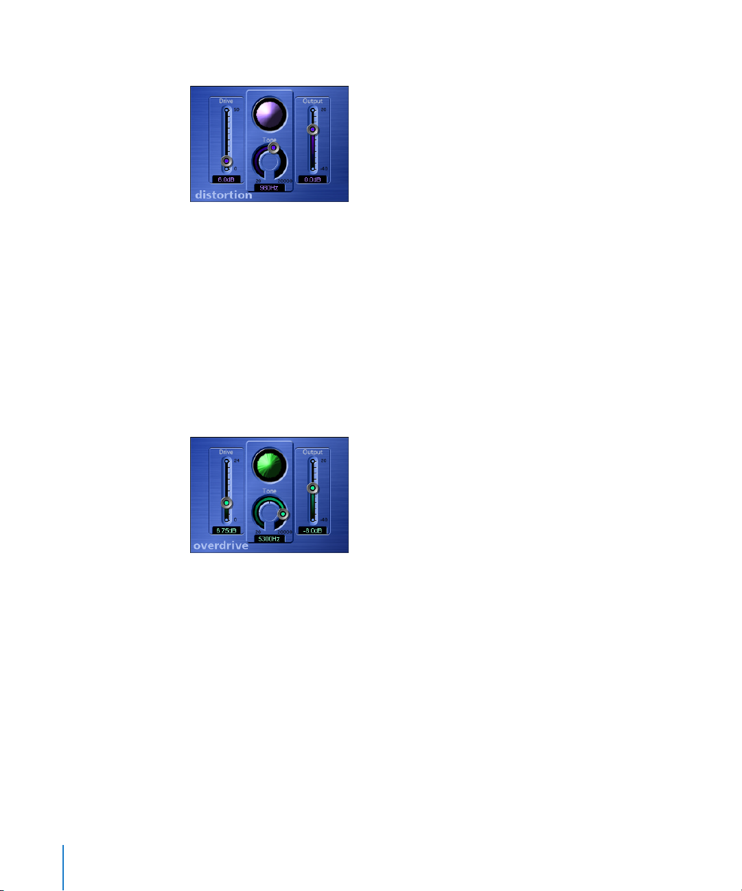
62 Chapter 5 Distortion
Distortion
This distortion effect simulates the lo-fi dirt generated by a bipolar transistor.
Move the Drive slider up to increasingly saturate the transistor. Generally, the distortion
created by the plug-in tends to increase the signal level, an effect that you can
compensate for with the Output slider. The Tone knob filters the harmonics-laden
distortion signal, delivering a somewhat less grating, softer tone.
The Distortion Eye is watching—it visually represents the Drive and Tone parameter
settings.
Overdrive
The Overdrive effect emulates the distortion of a field-effect transistor (FET). When
saturated, FETs generate warmer sounding distortion than bipolar transistors.
The Drive slider pushes the transistor over the edge and into overdrive. Generally, the
distortion created by the plug-in tends to increase signal levels, an effect that you can
compensate for with the Output slider.
The Tone knob lets you filter the harmonics-laden distortion signal, which delivers an
even warmer sound.
The Distortion effect’s Eye visually represents the settings of the Drive and Tone
parameters.
Page 63
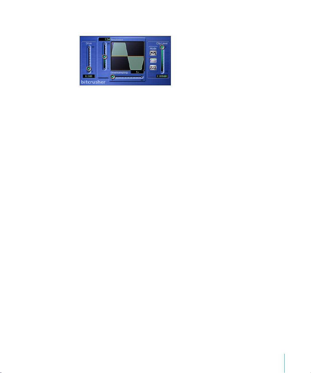
Chapter 5 Distortion 63
Bitcrusher
Bitcrusher is the ultimate digital distortion box. You can do all kinds of wild stuff with it,
such as recreate the 8-bit sound of the pioneering days of digital audio, create artificial
aliasing by dividing the sample rate, or distort signals so radically that they are
rendered unrecognizable.
Warning: The Bitcrusher can damage your hearing (and speakers) when operated at
high volumes.
The Drive slider boosts the level at the input of the Bitcrusher. Please note that this
tends to excite the clipping stage located at the output of the Bitcrusher as well.
The Resolution knob allows you to reduce the resolution from 24 bits down to 1 bit.
The number of bits is always an exponent of two. The range of available values is
equivalent to the exponents of two that a given sample rate can handle. As an
example, 65,536 different values are possible for 16 bits, whereas at 8 bits, you’re left
with just 256. The sonic image becomes ever more ragged as the values decrease
because the number of sampling errors increases, thus generating more distortion. At
extremely low bit resolutions, the amount of distortion can be greater than the level of
the usable signal.
The Downsampling slider lowers the sample rate. As an example, at a value of 2
(halved), the original 44.1 kHz signal is sampled at a rate of just 22.05 kHz. At a factor of
10, the rate is knocked all the way down to 4.41 kHz.
The Clip Level slider lets you define the point below the normal threshold that you want
the signal to start clipping. The Mode buttons are used to determine whether the signal
peaks that exceed the clip level are Folded, Cut, or Displaced (check out the graphics
on the buttons and the resulting waveform in the display). The kind of clipping that
occurs in standard digital systems is usually closest to that of the center mode (Cut).
Internal distortion may generate clipping similar to the types generated by the other
two modes.
Page 64
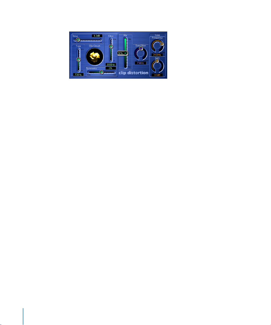
64 Chapter 5 Distortion
Clip Distortion
The Clip Distortion plug-in is a non-linear distortion effect that produces unpredictable
spectra. Beyond drastic distortions, it’s well suited for the simulation of warm tube
overdrive sounds.
The best way to learn what effect the various parameters have is to experiment with
them on different signal sources. As a starting point, the following describes what each
control basically does:
The signal is first amplified by the Drive value, which is a simple gain control. The signal
then passes through a highpass filter. The filter’s cutoff frequency is determined by the
Tone control. The actual non-linear distortion process is controlled by the Symmetry
parameter.
Once the signal has been distorted asymmetrically, the signal passes through a lowpass
filter. This filter’s cutoff frequency is determined by the Filter fader. The Mix parameter
combines the effected signal with the dry signal. This mixed signal then passes through
yet another lowpass filter, where the cutoff frequency is controlled by the Sum Filter
parameter. All filters have a slope of 6 dB/Oct.
The last stage of signal processing is a tunable shelving filter. If you set its Frequency to
about 12 kHz, it will behave like a normal treble control, as found in any mixer’s channel
strip or stereo hi-fi amplifier. Unlike such treble controls, this filter allows for boosts or
cuts of up to ±30 dB (Gain parameter). This somewhat unorthodox combination of
serially connected filters allows for gaps in the frequency spectra that can sound quite
good with this sort of non-linear distortion. The clip circuit graphic visually depicts
every parameter, with the exception of the shelving filter controls.
There are two more parameters in the Controls view: Input Gain and Output Gain.
These can be used to raise/lower the input and output signal levels by up to 30 dB.
Page 65
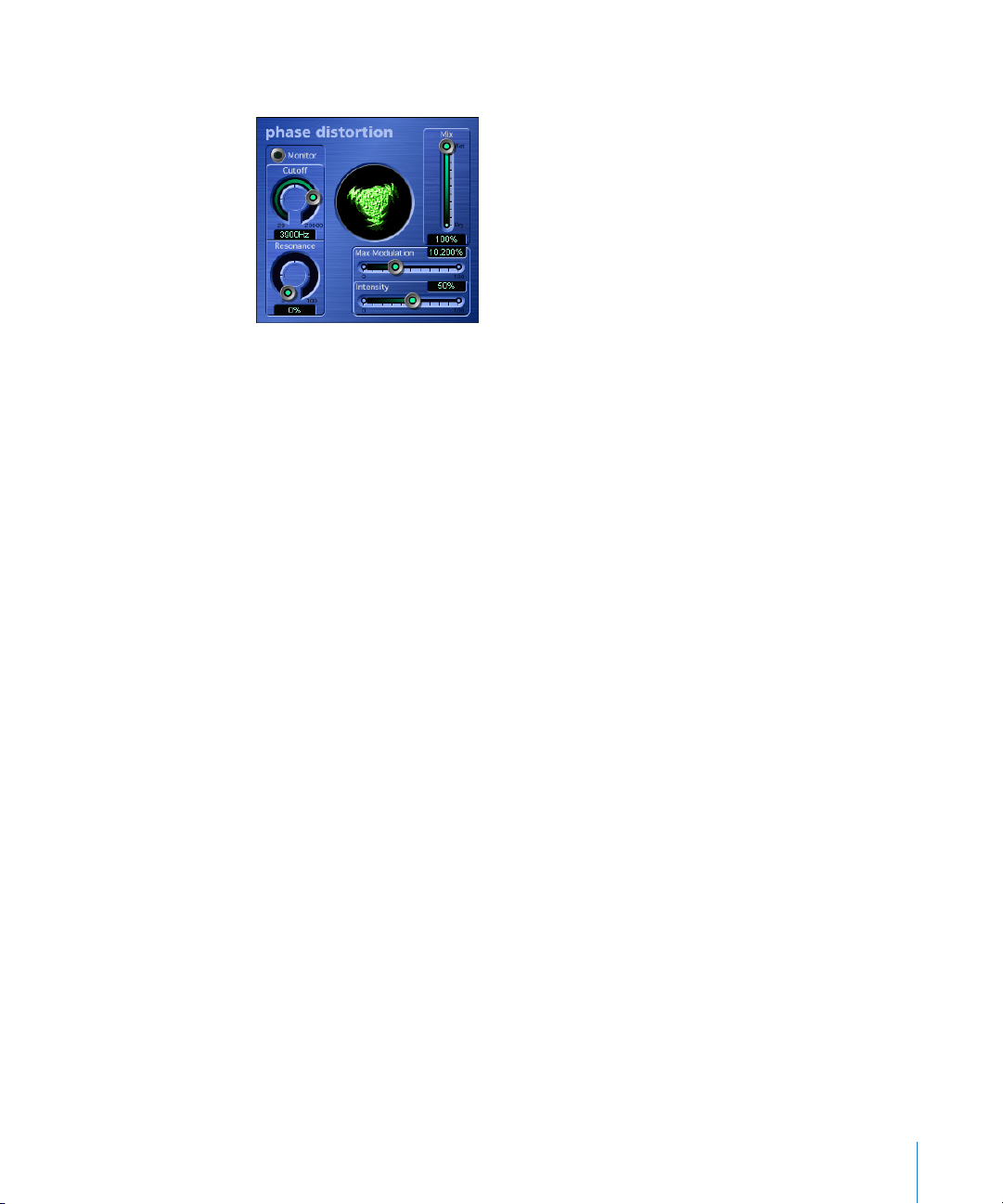
Chapter 5 Distortion 65
Phase Distortion
The Phase Distortion plug-in is based on a modulated delay line, much like the wellknown chorus or flanger effects. As opposed to these, the delay time is not modulated
by a low frequency oscillator (LFO), but rather by a lowpass-filtered version of the audio
input signal itself. This is how the signal modulates its own phase position.
In the signal flow of this effect, the parameters do the following:
The input signal only passes the delay line and is not affected by any other process. Mix
blends the effected signal with the original signal. The delay time is modulated by a
Side Chain signal—namely, the input signal. The input signal passes through a resonant
lowpass filter, the Cutoff frequency and Resonance of which can be set with dedicated
controls. You also can listen to the filtered Side Chain (instead of the Mix signal), if you
engage Monitor. The maximum delay time is set with Max Modulation. The amount of
modulation itself is controlled with Intensity.
In the Controls view, there is one more parameter which can’t be seen in the Plug-in
window. It is only valid for the stereophonic version of the effect. Normally, a positive
input value results in a longer delay time. If you engage Phase Reverse (On), positive
input values result in a reduction of the delay time on the right channel only.
Page 66

66 Chapter 5 Distortion
Distortion II
The Distortion II plug-in is based on the EVB3’s distortion effect. More information
about its parameters can be found in the EVB3’s “Distortion” section on page 473.
The Distortion II plug-in offers one additional parameter: the PreGain knob. This allows
you to raise the input signal by up to 20 dB or lower it by as much as 10 dB, in order to
provide a broader range of distortion colors.
Page 67
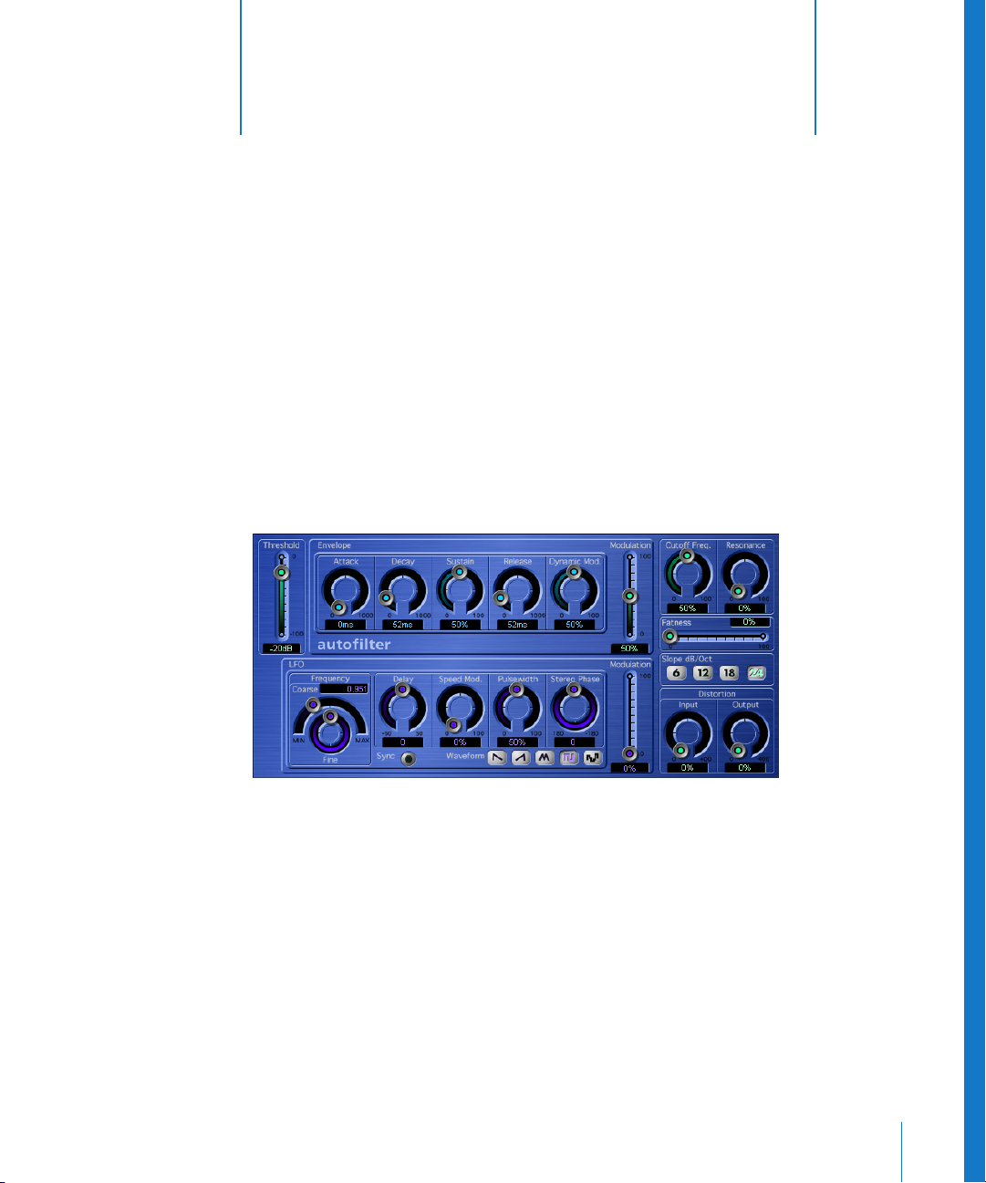
6
67
6 Filter
This chapter covers Logic’s filter effects.
The filter effects include the AutoFilter, Fuzz-Wah, EVOC 20 FB, EVOC 20 TO, Low/High
Pass Filter and Low/High Cut plug-ins. The EVOC 20 TO is based on a vocoder. Further
information about vocoders can be found in the chapter “Vocoder—Basics” on
page 167.
AutoFilter
The AutoFilter is an extremely versatile, resonance-capable lowpass filter, that offers a
couple of truly unique features. The most important parameters are located to the right
side of the Plug-in window: The Cutoff Freq. knob determines the point where the filter
kicks in. Higher frequencies are attenuated, lower frequencies are allowed to pass
through.
Page 68

68 Chapter 6 Filter
The Resonance knob emphasizes the frequency range surrounding the cutoff
frequency. When you turn the Resonance up sufficiently, the filter itself begins
oscillating (at the cutoff frequency). Self-oscillation is initiated before you max out the
Resonance parameter, just like the filters on the legendary Minimoog. When working
with Resonance, the manner in which the lowpass filter allows frequencies to pass
changes: higher Resonance values cause the filter to cut the bottom end, making the
signal sound thinner. The Fatness parameter compensates for this audio artefact. When
you turn Fatness up to its maximum value, the Resonance setting has no effect on the
response of the frequencies below the cutoff frequency.
The Slope buttons determine the steepness of the lowpass filter: frequencies above the
cutoff frequency are dampened by 6, 12, 18, or 24 dB per octave (in audio jargon, these
are called filters of the 1st, 2nd, 3rd, and 4th order). Even though the 24 dB filter is
largely the component of choice for synthesizer designers, be sure to experiment with
the other options, as they can also deliver pretty hip results. The Distortion Input and
Output parameters allow you to individually control each of the two distortion units—
one pre-input and the other post-output. Although the two distortion modules are
identical, their respective positions in the signal chain—before and after the filter,
respectively—enable them to generate remarkably different sounds.
All other AutoFilter parameters are used to dynamically modulate the cutoff frequency.
These fall into two sections: Envelope (ADSR, Envelope Generator) and LFO (Low
Frequency Oscillator, Modulation Generator).
The Threshold parameter applies to both sections, and analyzes the level of the input
signal. If the input signal level exceeds that of the variable Threshold level, the
envelope and LFO are retriggered. The Modulation slider of each section determines
the intensity of the control signal’s effect on the cutoff frequency.
Envelope: when the Threshold level is exceeded, the control signal is triggered at the
minimum value. Following a variable interval, the length of which is determined by the
Attack parameter, the signal reaches its maximum value. It drops in level during the
interval defined by the Decay value, and ends up at the Sustain value. Once the signal
level drops below the Threshold value, it falls all the way to its minimum value over the
time determined by the Release parameter. If the input signal falls below the Threshold
level before the control signal has reached the Sustain level, the Release phase is
triggered. The Dynamic Modulation parameter lets you modulate the peak value of the
Envelope section, by using the level of the input signal.
Page 69

Chapter 6 Filter 69
LFO: the wave shape used for LFO oscillation is determined by the Waveform buttons.
The choices are: descending sawtooth (saw down), ascending sawtooth (saw up),
triangle, pulse wave, or random (random values, Sample & Hold). Once you’ve selected
a waveform, you can shape the curve with the Pulsewidth knob. Use the Frequency
knobs to define the desired LFO frequency: Coarse sets a value between 0.1 and
10,000 Hz, Fine lets you adjust it in smaller increments. The Speed Mod. (Speed
Modulation) knob is used to modulate the LFO frequency independently of the input
signal level. If the input signal exceeds the Threshold level, the modulation width of the
LFO increases from 0 to the value specified for Modulation. You can also define the
amount of time this process takes, by entering the desired value with the Delay knob. If
the Sync button is activated, the waveform is started at 0° as soon as the Threshold is
exceeded.
Whenever you use the AutoFilter as a stereo plug-in, you can determine the phase
relationships of the LFO modulations on the two stereo sides, with the Stereo Phase
knob.
There are five additional parameters in the Controls view of the Autofilter.
The Volume parameter can lower the Volume by as much as −50 dB, allowing you to
compensate for higher levels when using Distortion, for example. If you switch Beat
Sync to On, the LFO is synchronized to the sequencer’s tempo. The speed values
include bar values, triplet values and more. These are determined by the Rate slider
directly below Beat Sync. Use Sync Phase to shift the phase relationship between the
LFO and the sequencer. Dry Signal sets the level ratio/portion of the non-effected (dry)
signal.
Page 70
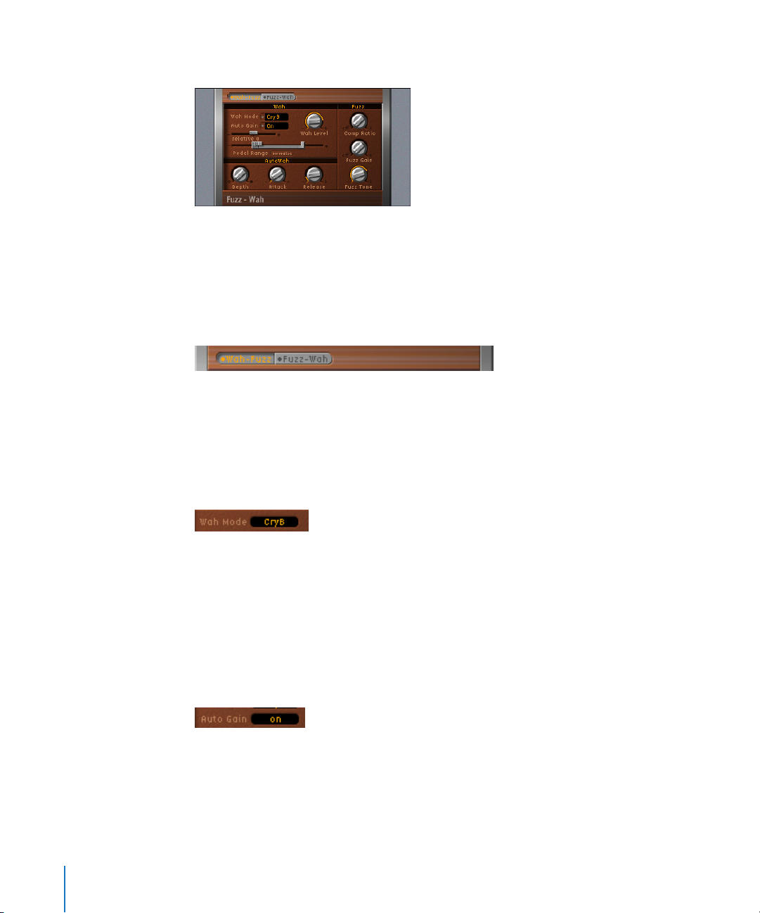
70 Chapter 6 Filter
Fuzz-Wah
The Fuzz-Wah effect is the standalone plug-in version of the EVD6’s Wah effect. It
incorporates additional compressor and distortion (Fuzz) facilities, and features some
additional parameters over the integrated EVD6 Wah. These are outlined below.
Parameters of the Fuzz-Wah
FX Order
This parameter allows to you select the order in which the Fuzz/Wah effects are placed.
Choices are: Fuzz –Wah or Wah–Fuzz.
Wah Mode
There are simulations of several classic wah effects, as well as some basic filter types
available. Available models are: off, ResoLP, ResoHP, Peak, CryB, Morl1, Morl2.
Wah Level
Can be used to adjust the level of the wah-filtered signal, relative to the original level.
Also see the Auto Gain section below.
Auto Gain
While sweeping through the main formants of the input signal, the output level of the
Wah may vary wildly, which is not always desirable. Activating the Auto Gain parameter
will automatically compensate for this side-effect. Range: on/off
To hear the difference Auto Gain can make:
• Switch Auto Gain to on.
• Raise the effect level to a value just below the mixer’s clipping limit.
• Make a sweep with a high relative Q setting.
• Now switch Auto Gain to off, and repeat the sweep.
Page 71
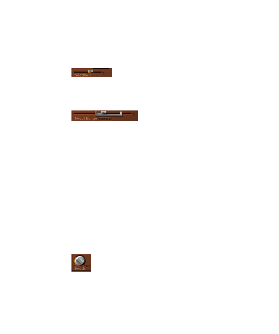
Chapter 6 Filter 71
Warning: Please take care while doing this, or your ears and speaker system may be
damaged.
Relative Q
The quality of the main filter peak can be increased/decreased, relative to the model
setting, thereby obtaining a sharper/softer wah sweep. When set to a value of 0, the
original setting of the model is active. Range: −1.00 to +1.00 (0.00 is the default)
Pedal Range
Common MIDI foot pedals have a much larger mechanical range than most classic Wah
pedals.
The exact sweep range of the wah filter effected by the MIDI foot pedal is set with the
Pedal Range parameters. The highest and lowest possible value reached by the pedal is
graphically represented by a gray bracket around the Pedal Position fader (see below).
The left and right limit is set by clicking and moving it with the mouse. Additionally
both values can be moved simultaneously by clicking in the center of the bracket and
moving it to the left or right.
Pedal Position
This parameter represents the current position of the Wah pedal.
To control and automate the Pedal Position via an external MIDI controller for example
a MIDI pedal, your Logic environment has to be prepared accordingly. For more
information please read “Controlling the EVD6 via MIDI” on page 502.
AutoWah Depth
In addition to using MIDI foot pedals (see above), the wah effect can be controlled
using the Auto Wah facility. The sensitivity of the Auto Wah can be set with the Depth
parameter. Range: 0.00 to 10 0. (See also the “Envelope (Depth)” section, from page 500
onwards.)
Page 72
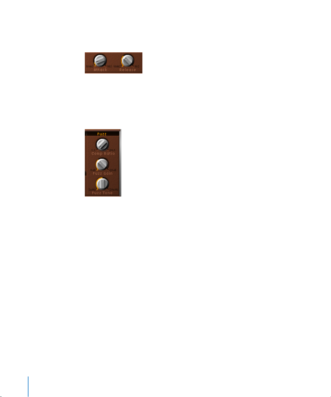
72 Chapter 6 Filter
AutoWah Attack/Release
These parameters allow you to define how much time it takes for the Wah filter to open
and close. Range (in milliseconds): 10 to 10,000
Comp Ratio
The Comp Ratio of the integrated compressor can be adjusted between 1:1 (no
compression) and 30:1. The Compressor is tied to the Fuzz effect, and always precedes
it. As such, the FX Order parameter is very important for placement of the Compressor
in the effects chain.
Fuzz Gain
Controls the level of Fuzz (distortion). Range: 0 dB to 20 dB.
Fuzz Tone
The integrated Fuzz effect can be adjusted, tonally, with this parameter. Range: 2000 Hz
to 20,000 Hz
EVOC 20 Filterbank
The EVOC 20 FB consists of two formant filter banks, which are also used in Logic’s
EVOC 20 PS vocoder. More information on the filter banks are found in “How Does a
Filter Bank Work?” on page 168.
The input signal runs through both filter banks in parallel. Each bank features
independent volume faders for each band, allowing levels to be set freely—ranging
from unchanged through to silence. The latter completely suppresses the selected
formants in the overall sound spectrum. Use of the Formant Stretch and Formant Shift
parameters provide total control over the position and width of the filter bands. In
addition, you can also crossfade between the two filter banks.
Page 73
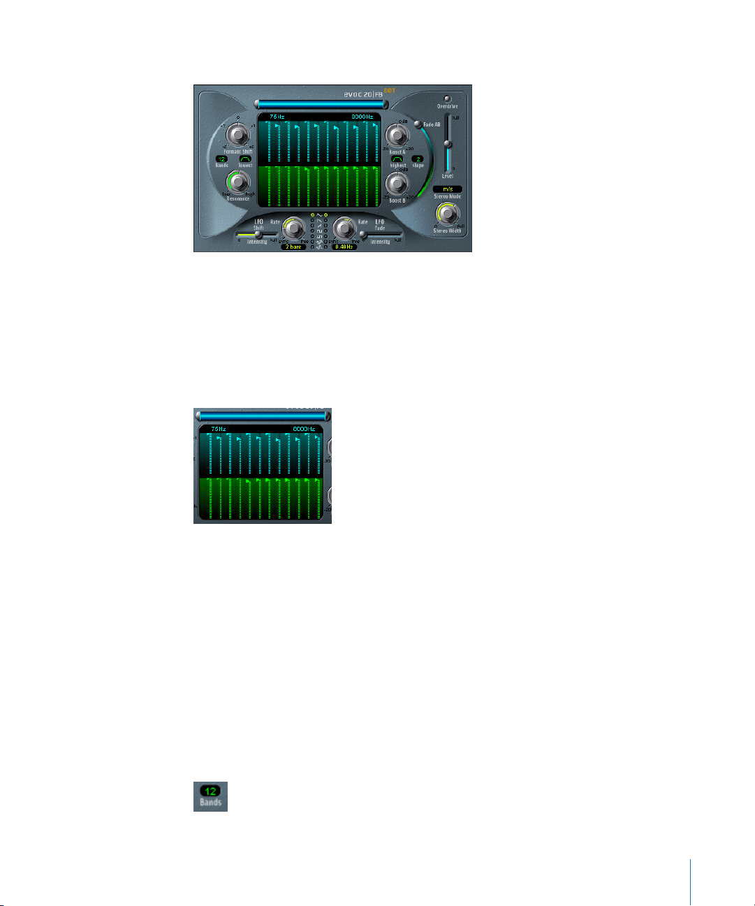
Chapter 6 Filter 73
Parameters of the EVOC 20 FB
The EVOC 20 FB interface is divided into three main sections. These are the Formant
Filter, Modulation, and Output areas.
The Formant Filter Area
The Formant Filter Window
The Formant Filter window is divided into two sections by a horizontal line. The upper
half applies to the Filter Bank A, and the lower half to the Filter Bank B.
The individual vertical bars in each bank of settings are faders which represent the level
of a particular frequency band/formant. To adjust each fader, simply click-hold on the
desired bar and drag up or down.
Complex bar curves are easily created by “painting” them in: Click and hold the mouse
button next to a bar on the blue or green portion of the background, and drag left or
right over the bars within the editing field. The length of the bars will be adjusted in
accordance with the mouse movement. This method makes editing multiple frequency
band levels quick and convenient.
Bands
The Bands parameter determines the number of frequency bands used by the
EVOC 20 FB. It ranges from 5 to 20.
Page 74
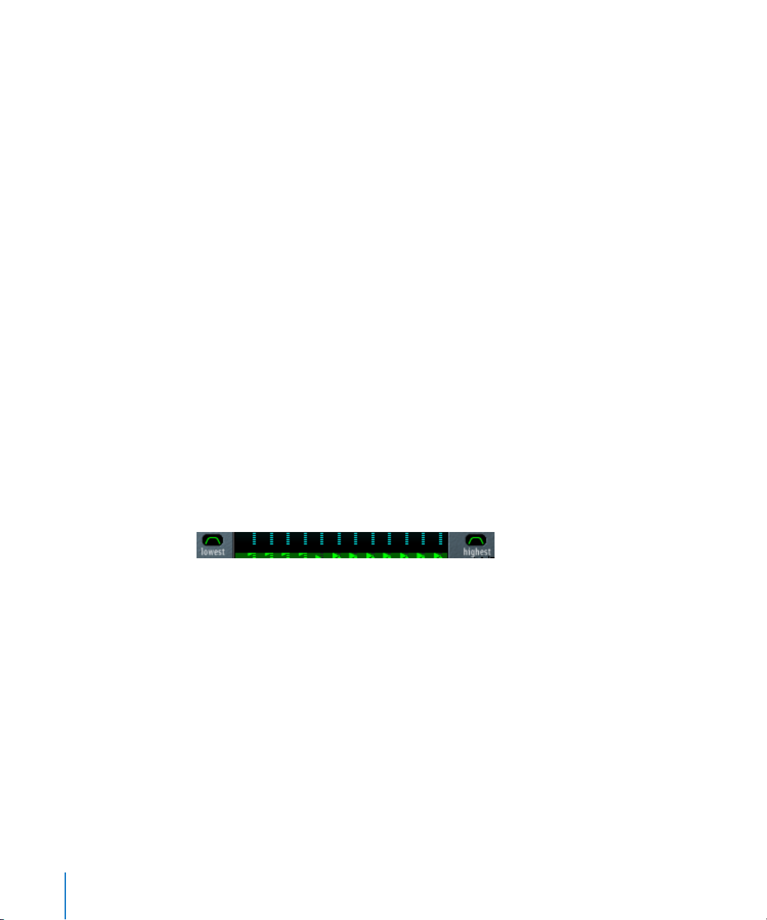
74 Chapter 6 Filter
Note: Increasing the number of bands also increases the processor overhead.
High/Low Frequency
The blue bar shown just beneath the EVOC label is a multi-part control which is used to
determine the lowest and highest frequencies allowed to pass by the filter. Frequencies
which fall outside these boundaries will be cut. All filter bands are distributed evenly
across the range defined by the High/Low Frequency values.
• To adjust the Low Frequency value, simply click-hold on the silver slider to the left of
the blue bar, and drag to the right (or left). The value range is 75–750 Hz.
• To adjust the High Frequency value, simply click-hold on the silver slider to the right
of the blue bar, and drag to the left (or right). The value range is 800–8000 Hz.
• To adjust both sliders simultaneously, click on the area between the slider halves
(directly on the blue bar) and drag to the left or right.
• You can make changes to the High/Low Frequency values directly by using your
mouse as a slider on the numerical entries—80 and 8000 Hz in the diagram.
Lowest/Highest
These parameters can be found in the two small switches on either side of the Formant
Filter window. These switches determine whether the lowest and the highest filter
bands are bandpass filters (just like all the bands between them), or whether they act
as lowpass/highpass filters, respectively. Click once on them to switch between the two
curve shapes available.
• In the Bandpass setting, the frequencies below/above the lowest/highest bands are
ignored.
• In the Highpass or Lowpass setting, all frequencies below the lowest (or above the
highest) bands will also be treated.
Slope
The pull-down menu Slope determines the amount of filter slope applied to all filters of
both filter banks. Choices are 1 (filter attenuation of 6 dB/Oct.) and 2 (filter attenuation
of 12 dB/Oct.): 1 sounds softer, 2 sounds tighter.
Boost A/B Controls
The Boost A and Boost B knobs allow an increase or cut in the overall gain of the A and
B filter banks. Their range is ±20 dB. To adjust, click-hold and drag up or down with the
mouse.
Note: You will need these controls, as the filter bank achieves its sounds by turning
down the level of one or more filter bands. To make up for the resulting energy loss,
use Boost.
Page 75
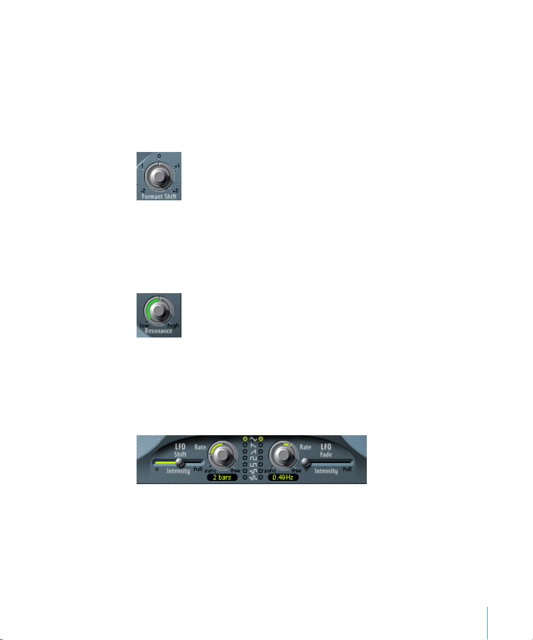
Chapter 6 Filter 75
Note: Boost is also quite handy to adjust the levels of both filter banks to each other, so
that using Fade A/B (see below) leads only to a sound color change, but not to a level
change.
Fade AB Control
The Fade AB crossfades between the A and B filter bank. At its extreme top or bottom
position, you will only hear one of the filter banks.
Formant Shift
Moves the position of all bands in both filter banks up and down the frequency range.
Note: You can jump directly to the values −0.5, −1, 0, +0.5 and +1.0 by clicking on their
numbers.
Resonance
Resonance is responsible for the basic sonic character of both filter banks: low settings
give it a soft character, high settings will lead to a more snarling, sharp character.
Increasing the value for Resonance emphasizes the middle frequency of each frequency
band.
Modulation Parameters
The Modulation (LFO) area controls the Formant Shift and Fade A/B parameters of the
EVOC 20 FB. It allows synchronous/non-synchronous modulation in bar, beat (triplet) or
free values.
• LFO Shift, on the left-hand side, controls Formant Shift modulation of the filter bands.
• LFO Fade controls the Fade AB parameter.
Page 76

76 Chapter 6 Filter
Waveform
The Waveform switches allow the selection of the waveform type used by LFO Shift and
LFO Fade. A selection of Triangle, falling and rising Sawtooth, Square up and down
around zero (bipolar), Square up from zero (unipolar), a random stepped waveform
(S&H), and a smoothed random waveform is available for each LFO.
Intensity
The Intensity sliders control the amount of Formant Shift and Fade A/B modulation by
the respective LFOs.
Rate
These knobs determine the speed of the modulation. Values to the left of the center
positions are synchronized with the sequencer’s tempo and include bar values, triplet
values and more. Values to the right of the center positions are non-synchronous and
displayed in Hertz.
Note: The Formant Shift and Fade LFO modulations are the keys to the most
extraordinary sounds of the EVOC 20 FB: Make sure to set up totally different or
complementary filter curves in both filter banks. Use rhythmic material like a drumloop
as an input signal. Set up tempo-synchronized modulations—with different Rates for
each LFO—for Formant Shift and Fade A/B. And then try a tempo-synchronized Tape
Delay after the EVOC 20 FB. You will end up with unique rhythms.
Page 77
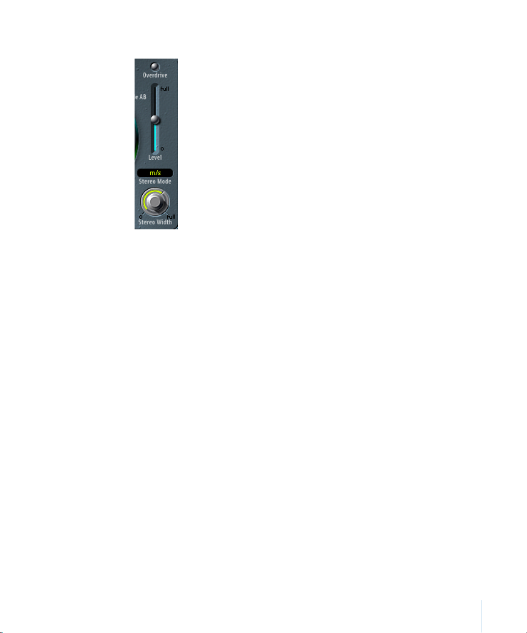
Chapter 6 Filter 77
Output Section
Overdrive
This switch enables/disables the Overdrive circuit of the EVOC 20 FB.
Note: To actually hear the Overdrive effect, you may need to boost the level of one or
both filter banks.
Level
The Level slider controls the level of the EVOC 20 FB’s output signal.
Stereo Mode
This pull-down menu determines the input/output mode of the EVOC 20 FB. Choices
are: m/s—mono input to stereo output and s/s—stereo input to stereo output.
• The Stereo Mode should be set to m/s if the signal going into the EVOC 20 FB is
monophonic, for example a mono audio track.
• Stereo/stereo (s/s) is the preferred setting for stereo input signals. In this case, the
stereo signal is processed by separate filter banks for the left and right channels.
When using the m/s Mode on stereo input signals, the stereo signal is first summed
to mono before it is passed on to the filter banks.
Stereo Width
Stereo Width distributes the output signals of the filter bands in the stereo field.
• In the left position, the output of all bands are centered.
• In the center position, the output of all bands ascends from left to right.
• In the right position, the bands are output evenly on the left and the right channel.
The stereo/stereo mode (s/s) uses one A/B filter bank per channel. The positioning of
the frequency bands correspond to that described above, but the bands of each filter
bank ascend in opposing directions, from left to right.
Page 78

78 Chapter 6 Filter
MIDI Controllers Received
The following tables show the CC numbers used when the following MIDI preference is
active: Options > Settings > MIDI Options > (Version 4.x behavior).
Filter Bands Band Level Bank A Bank B
Band 1 CC #64 CC #96
Band 2 CC #65 CC #97
Band 3 CC #66 CC #98
Band 4 CC #67 CC #99
Band 5 CC #68 CC #100
Band 6 CC #69 CC #101
Band 7 CC #70 CC #102
Band 8 CC #71 CC #103
Band 9 CC #72 CC #104
Band 10 CC #73 CC #105
Band 11 CC #74 CC #106
Band 12 CC #75 CC #107
Band 13 CC #76 CC #108
Band 14 CC #77 CC #109
Band 15 CC #78 CC #110
Band 16 CC #79 CC #111
Band 17 CC #80 CC #112
Band 18 CC #81 CC #113
Band 19 CC #82 CC #114
Band 20 CC #83 CC #115
Boost Bank A CC #84
Bank B CC #116
Fade A/B CC #117
Formant Filter Bands CC #85
FF Low Freq CC #88
FF Hi Freq CC #89
Formant Shift CC #90
FF Resonance CC #91
Slope CC #92
FF Low/Bandpass Select CC #119
FF High/Bandpass Select CC #120
Page 79

Chapter 6 Filter 79
EVOC 20 TO
The EVOC 20 TO is a vocoder equipped with a monophonic pitch tracking oscillator,
hence the TO in its name (more information about vocoders can be found in the
chapter “Vocoder—Basics” on page 167). Non-technically, this allows the EVOC 20 TO to
follow (track) the pitch of a monophonic incoming audio signal. If the audio signal is a
vocal melody, for example, the individual pitches of the sung notes will be tracked and
mirrored by the Synthesis engine.
The EVOC 20 TO derives its synthesis signal from its monophonic tracking oscillator.
Alternatively to the tracking oscillator, the EVOC 20 TO can use a freely selectable audio
signal as the synthesis signal.
Note: For good pitch tracking, it is essential that the signal is monophonic (one pitch at
a time) and as dry as possible. Absolutely avoid background noises. As an example,
using a voice already processed with even a slight reverb will deliver pretty strange
results. The results will be even stranger when signals with no audible pitch are used—
such as drumloops. The resulting artefacts might, however, be exactly what you’re after
in some situations.
It should be noted that the EVOC 20 TO uses a Side Chain, allowing the use of another
track as the analysis and/or synthesis signal. In the gray area at the top of the Plug-in
window, click-hold on the Side Chain pull-down menu, and select the desired Audio
track. In the Mixer, adjust the volume levels of the EVOC 20 TO and the audio track used
for the Side Chain to taste.
The EVOC 20 TO is not limited to pitch tracking effects. It can vocode a signal by itself,
making it very useful for unusual filter effects. Try this with different Resonance, Formant
Shift and Formant Stretch settings.
As both analysis and synthesis input signals are freely selectable, you can even vocode
an orchestra with train noises, for example.
LFO 1 (Shift) LFO 1 Rate CC #93
LFO 1 Waveform Select CC #94
LFO 1 Intensity CC #95
LFO 2 (Fade) LFO 2 Rate CC #121
LFO 2 Waveform Select CC #122
LFO 2 Intensity CC #123
Output Level CC #124
Mono/Stereo Select CC #87
Stereo Width CC #86
Filter Bands Band Level Bank A Bank B
Page 80
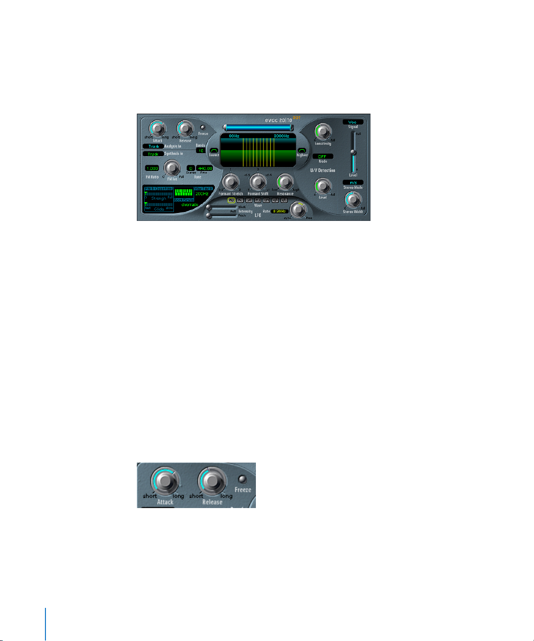
80 Chapter 6 Filter
The EVOC 20 TO can be used in the insert slots of Audio, Audio Input, Bus, Master, and
Audio Instrument channels.
The signal path of the EVOC 20 TO is shown in the block diagram on page 190.
Parameters of the EVOC 20 TO
The EVOC 20 TO interface is divided into five main sections. From left to right, these are
the Analysis/Synthesis, Formant/Filter, Modulation, Unvoiced/Voiced (U/V) Detection and
Output areas.
Analysis In Parameters
Attack
The Attack parameter determines how quickly each envelope follower coupled to each
Analysis filter band reacts to rising signals. Longer Attack times result in a slower
tracking response to transients of the Analysis input signal.
Note: A long Attack time on percussive input signals (a spoken word or hi-hat part, for
example) will translate into a less articulated vocoder effect. Set Attack as low as
possible to achieve precise articulation.
Release
The Release parameter determines how quickly each envelope follower coupled to each
Analysis filter band reacts to falling signals. Longer Release times make transients of the
Analysis input signal sound for a longer period of time at the Vocoder’s output.
Note: A long Release time on percussive input signals (a spoken word or hi-hat part, for
example) will translate into a less articulated vocoder effect. Release times that are too
short result in rough, grainy vocoder sounds. Release values of around 8 to 10 ms have
proven to be useful starting points.
Page 81

Chapter 6 Filter 81
Freeze
The Freeze button holds the current analysis sound spectrum indefinitely.
The “frozen” Analysis signal can capture a particular characteristic of the source signal,
which is then imposed as a complex sustained filter shape on the Synthesis section.
Using a spoken word pattern as a source, for example, the Freeze parameter could
capture the attack or tail phase of an individual word within the pattern—the vowel a,
for example.
With Freeze engaged, the Analysis filter bank ignores the input source until it is
disengaged.
Another use of the Freeze parameter (which can be automated) could be to
compensate for people’s inability to sustain sung notes for a long period without
taking a breath. If the Synthesis signal needs to be sustained, when the Analysis source
signal (a vocal part) isn’t, Freeze can be used to lock the current formant levels (of a
sung note), even during gaps in the vocal part—between words in a vocal phrase.
Note: When the Freeze parameter is used, the Attack and Release parameters have no
effect.
Analysis In (pull-down menu)
This pull-down menu determines the Analysis signal source—Track or Side Chain. To
switch between them, use the mouse as a slider and drag vertically.
• Track—allows you to use the audio track, into which the EVOC 20 TO is inserted, as
the Analysis signal.
• Side Chain—allows you to use another audio track as the Analysis signal. The
selection of the actual Side Chain source track is achieved by click-holding on the
Side Chain pull-down menu in the gray area at the top of the Plug-in window.
Note: If no Side Chain track is assigned in the Side Chain pull-down menu, the track’s
signal will be used.
Synthesis In Parameter
Synthesis In (pull-down menu)
This pull-down menu determines the Synthesis signal source—Osc(illator), Track or Side
Chain. To switch between them, use the mouse as a slider and drag vertically.
• Oscillator—allows you to use the built-in monophonic tracking oscillator. The
oscillator tracks the pitch of the Analysis input signal. Selection of the Oscillator
activates the other parameters in the Synthesis section. If Osc is not selected, the FM
Ratio, FM Int and other parameters in this area have no effect.
Page 82
82 Chapter 6 Filter
• Track—allows you to use the audio track, into which the EVOC 20 TO is inserted, as
the Synthesis source signal.
• Side Chain—allows you to use another audio track as the source material for the
Synthesis section. Selection of the Side Chain track is achieved by click-holding on the
Side Chain pull-down menu in the gray area at the top of the Plug-in window.
Note: If no Side Chain track is assigned in the Side Chain pull-down menu, the track’s
signal will be used.
Bands
The Bands window determines the number of frequency bands used by the
EVOC 20 TO. It ranges from 5 to 20. Adjustments are made by using the mouse as a
slider. The greater the number of bands, the more precisely the sound can be reshaped.
Note: Increasing the number of bands also increases the processor overhead.
The Tone Generator of the Tracking Oscillator
Depending on the position of the FM Int control, the tracking oscillators delivers either;
a sawtooth wave or the signal of an FM tone generator.
The FM tone generator consists of two oscillators, each generating a sine wave. The
frequency of Oscillator 1 is linearly modulated by Oscillator 2. This deforms the sine
wave of Oscillator 1 to a waveform with rich harmonic structure. Its harmonic structure
depends on the modulation intensity and the frequency ratio of both oscillators.
Tune
Coarse Tune offsets the pitch of the oscillator in semitones by up to ±2 octaves.
Fine Tune: The default value is concert pitch A = 440 Hz. The range is from 425.00 to
455.00 Hz.
Page 83
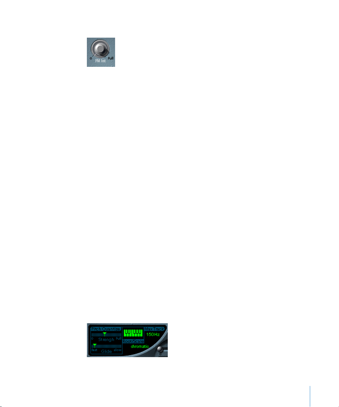
Chapter 6 Filter 83
FM Int
This knob selects the basic waveform and controls the intensity of FM modulation.
• If set to 0, the FM tone generator is disabled, and a sawtooth wave is generated
instead.
• If set to values higher than 0, the FM tone generator is activated. Higher values result
in a more complex and brighter sound.
FM Ratio
The FM Ratio (value range 0.5 to 3.5) knob defines the ratio between the Carrier and
Modulator frequencies—the frequencies of Oscillators 1 and 2. This setting defines the
basic character of the sound.
With even-numbered values or their multiples, harmonic sounds are produced. With
odd-numbered values or their multiples, inharmonic sounds are produced, which we
perceive as being metallic sounding.
• An FM Ratio of 1.000 produces results resembling a sawtooth waveform.
• An FM Ratio of 2.000 produces results resembling a square wave with a pulse width
of 50%.
• An FM Ratio of 3.000 produces results resembling a square wave with a pulse width
of 33%.
FM Ratio is only relevant if FM Int is not set to 0.
Pitch Quantize
The Pitch Quantize, Root/Scale and Max Track controls, in conjunction with the piano
keys of the onscreen keyboard, control the automatic pitch correction facility (Pitch
Quantize) of the tracking oscillator. Pitch Quantize, in conjunction with the Root/Scale
and Max Track parameters, can be used to constrain the pitch of the tracking oscillator
to a scale or chord. This allows subtle or savage pitch corrections, and can be used
creatively on unpitched material with high harmonic content, such as cymbals and
high-hats. To use pitch quantization, the Strength parameter must be set above a value
of zero, and at least one of the onscreen keyboard keys needs to be activated.
Page 84
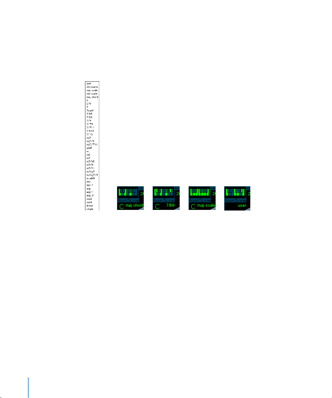
84 Chapter 6 Filter
• Strength—determines how pronounced the automatic pitch correction is.
• Glide—determines the amount of time the pitch correction takes, allowing sliding
transitions to the quantized pitches.
Root/Scale
The Root and Scale parameters, in combination with the onscreen keyboard, define the
pitch(es) that the tracking oscillator is quantized to.
• If you click on the value shown below the word Scale, a pull-down menu opens. Here
you can select a scale or chord. See the listing of preset scales and chords shown
alongside.
• Root selects the root key of the respective scale or chord. The Root parameter is not
displayed when chromatic or user is selected.
• Any combination of keys can be activated by clicking on the notes of the onscreen
keyboard. Activated keys are illuminated. To disable any active notes on the
keyboard, simply click on the note a second time. The Scale display will change to
user as soon as any key is edited.
• The previously displayed scale or chord is used as the starting point when creating a
user scale. This allows you to select a preset scale or chord, and then modify it by
clicking on the notes of the onscreen keyboard.
• The last edit will be remembered. You can select a new preset scale or chord, and as
long as you don’t make any changes you can always jump back to the previously set
user scale.
As with all Logic plug-ins, the Root and Scale parameters, and the keys of the onscreen
keyboard can be automated.
Page 85
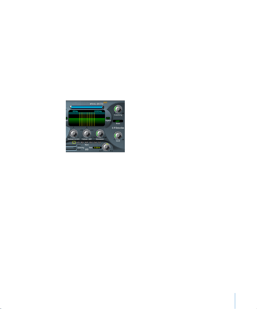
Chapter 6 Filter 85
Max Track
This parameter cuts the high frequencies of the analysis signal, making the pitch
detection more robust. Should the pitch detection produce unstable results, reduce the
Max Track parameter value to the lowest possible setting.
Formant Filter
The Formant Filter Window
The Formant Filter window is divided into two sections by a horizontal line. The upper
half applies to the Analysis section and the lower half to the Synthesis section. Changes
made to the High/Low frequency parameters, the Bands parameter or the Formant
Stretch and Formant Shift parameters will result in visual changes to the Formant Filter
window. This provides you with invaluable feedback on what is happening to the signal
as it is routed through the two formant filter banks.
High/Low Frequency
The blue bar shown just beneath the EVOC 20 TO logo is a multi-part control which is
used to determine the lowest and highest frequencies allowed to pass by the filter
section. The length of the blue bar represents the frequency range for analysis and
synthesis. Frequencies of any audio input which fall outside these boundaries will be
cut. All filter bands are distributed evenly across the range defined by the High/Low
Frequency values.
• To adjust the low frequency value, simply click-hold on the silver slider to the left of
the blue bar, and drag to the right (or left). The value range is 75–750 Hz.
• To adjust the high frequency value, simply click-hold on the silver slider to the right
of the blue bar, and drag to the left (or right). The value range is 800–8000 Hz.
• To adjust both sliders simultaneously, click on the area between the slider halves
(directly on the blue bar) and drag to the left or right.
• You can make changes to the High/Low Frequency values directly by using your
mouse as a slider on the numerical entries—80 and 8000 Hz in the diagram.
Page 86
86 Chapter 6 Filter
Lowest/Highest
These parameters can be found in the two small fields on either side of the Formant
Filter window. These switches determine whether the lowest and highest filter bands
are bandpass filters (just like all the bands between them), or whether they act as
lowpass/highpass filters, respectively. Click once on them to switch between the two
curve shapes available.
• In the bandpass setting, the frequencies below/above the lowest/highest bands are
ignored on analysis and synthesis.
• In the highpass (or lowpass) setting, all frequencies below the lowest (or above the
highest) bands will be considered for analysis and synthesis.
Formant Stretch
This parameter alters the width and distribution of all bands in the Synthesis filter bank,
extending or narrowing the frequency range defined by the blue bar (Low/High
Frequency parameters) for the Synthesis filter bank.
If Formant Stretch is set to 0, the width and distribution of the bands in the Synthesis
filter bank is equal to the width of the bands in the Analysis filter bank. Low values
narrow the width of each band, while high values widen it. The control range is from
0.5 to 2 (as a ratio of the overall bandwidth).
Note: You can jump directly to a value of 1 by clicking on its number.
Formant Shift
Formant Shift moves the position of all bands in the Synthesis filter bank up and down.
With Formant Shift set to 0, the position of the bands in the Synthesis filter bank is equal
to the position of the bands in the Analysis filter bank. Positive values will move the
bands up in frequency, while negative values will move them down in respect to the
Analysis filter bank.
Note: You can jump directly to the values −0.5, −1, 0, +0.5 and +1 by clicking on their
numbers.
Note: When combined, Formant Stretch and Formant Shift alter the formant structure of
the resulting vocoder sound, and can result in some interesting timbre changes. As an
example, using speech signals and tuning Formant Shift up results in Mickey Mouse
effects.
Page 87
Chapter 6 Filter 87
Note: Formant Stretch and Formant Shift are especially useful if the frequency spectrum
of the Synthesis signal does not complement the frequency spectrum of the Analysis
signal. You could create a Synthesis signal in the high frequency range from an Analysis
signal which mainly modulates the sound in a lower frequency range, for example.
Resonance
Resonance is responsible for the basic sonic character of the Vocoder: low settings give
it a soft character, high settings will lead to a more snarling, sharp character. Increasing
the value for Resonance emphasizes the middle frequency of each frequency band.
Note: The use of either, or both, of the Formant Stretch and Formant Shift parameters
can result in the generation of unusual resonant frequencies when high Resonance
settings are used.
Modulation Parameters
The LFO can modulate …
• the frequency (Pitch) of the tracking oscillator (vibrato) or
• the Formant Shift (Shift) parameter of the Synthesis filter bank.
It allows synchronous/non-synchronous modulation in bar, beat (triplet) or free values.
Wave
The Wave switches allow the selection of a waveform type to be used by the LFO. A
selection of Triangle, falling and rising Sawtooth, Square up and down around zero
(bipolar, good for trills), Square up from zero (unipolar, good for changing between two
definable pitches), a random stepped waveform (S&H), and a smoothed random
waveform is available. Simply click on the appropriate button to select a waveform
type.
Intensity
The Intensity sliders control the amount of Formant Shift and Pitch modulation (Vibrato)
by the LFO.
Page 88
88 Chapter 6 Filter
Rate
This knob determines the speed of the modulation. Values to the left of the center
positions are synchronized with the sequencer’s tempo and include bar values, triplet
values and more. Values to the right of the center positions are non-synchronous and
displayed in Hertz (cycles per second).
Note: The ability to use synchronous bar values could be used to perform a formant
shift every four bars on a one bar percussion part, which is being cycled. Alternately,
you could perform the same formant shift on every eighth note triplet within the same
part. Either method can generate interesting results, and can lead to new ideas, or a
new lease of life on old audio material.
U/V Detection
Please refer to “Analyzing Speech Signals”, from page 169 onwards, for an explanation
of the U/V Detection principle.
Speech intelligibility is highly dependent on high frequency content, as human hearing
is reliant on these upper-end frequencies to determine syllables within words. Bear this
fact in mind when using the EVOC 20 TO, and take care with filter frequency settings in
the Synthesis and Formant Filter sections.
To aid intelligibility, it may be worthwhile using equalization to boost particular
frequencies in the mid to high frequency range, before processing the signal with the
EVOC 20 TO. Please see the “Tips for Better Speech Intelligibility” on page 169 for
further information.
Sensitivity
This parameter determines how responsive the U/V detection is. By turning this knob
to the right, more of the individual unvoiced portions of the input signal are
recognized.
When high settings are used, the increased sensitivity to unvoiced signals can lead to
the U/V source—determined by the Mode parameter—being used on the majority of
the input signal, including voiced signals. Sonically, this results in a sound that
resembles a radio signal which is breaking up and contains a lot of static or noise.
Page 89
Chapter 6 Filter 89
Mode
Here, you select the sound source(s) which can be used to replace the unvoiced content
of the input signal. Possible settings are Off, Noise, Noise + Synth, or Blend.
• Noise—uses noise alone for the unvoiced portions of the sound.
• Noise + Synth—uses noise and the synthesizer for the unvoiced portions of the
sound,
• Blend—uses the Analysis signal after it has passed through a highpass filter, for the
unvoiced portions of the sound. This filtered analysis signal is then mixed with the
EVOC 20 TO output signal. The Sensitivity parameter has no effect on this setting.
Level
Level controls the amount of the signal (Noise, Noise + Synth, or Blend) used to replace
the unvoiced content of the input signal.
Warning: Care should be taken with this control, particularly when a high Sensitivity
value is used, to avoid internally overloading the EVOC 20 TO.
Output Parameters
Signal
This pull-down menu offers the choice of Voc(oder), Syn(thesis) and Ana(lysis). Selection
of one of these determines the signal that you wish to send to the EVOC 20 TO’s main
outputs. To hear the vocoder effect, Signal must be set to Voc. The other two settings
are useful for monitoring purposes.
Page 90
90 Chapter 6 Filter
Level
Level controls the volume of the EVOC 20 TO’s output signal.
Stereo Mode
This pull-down menu determines the input/output mode of the Synthesis filter bank.
Choices are: m/s—mono input to stereo output and s/s—stereo input to stereo output.
Note: The Stereo Mode should be set to m/s if the signal going into the Synthesis filter
bank is monophonic or Synthesis In is set to Osc.
Note: Stereo/stereo (s/s) is the preferred setting for stereo Synthesis input signals. In
this case, the stereo signal is processed by a separate filter bank for the left and right
channels. When using the m/s mode on stereo Synthesis input signals, the stereo signal
is first summed to mono before it is passed on to the Synthesis filter bank.
Stereo Width
Stereo Width distributes the output signals of the Synthesis section’s filter bands in the
stereo field.
• In the left position, the output of all bands are centered.
• In the center position, the output of all bands ascends from left to right.
• In the right position, the bands are output—alternately—on the left and right
channels.
Note: The stereo/stereo mode (s/s) uses one filter bank per channel. The positioning of
the frequency bands correspond to that described above, but the bands of each filter
bank ascend in opposing directions, from left to right.
Page 91

Chapter 6 Filter 91
MIDI Controllers Received
The following tables show the CC numbers used when the following MIDI preference is
active: Options > Settings > MIDI Options > (Version 4.x behavior).
Sidechain Analysis Attack CC #79
Release CC #80
Freeze CC #78
Synthesis Input Mode CC #65
Bands CC #66
FM Ratio CC #86
FM Intensity CC #87
Coarse Tune CC #85
Fine Tune CC #105
Pitch Quantize Strength CC #90
Root Scale Key CC #103
Root Scale Presets CC #104
Max Track CC #88
Glide Time CC #89
Formant Filter FF Low Freq CC #67
FF Hi Freq CC #68
Formant Shift CC #69
Formant Stretch CC #74
FF Resonance CC #75
FF Low/Bandpass Select CC #76
FF High/Bandpass Select CC #77
LFO LFO Rate CC #70
LFO Waveform Select CC #71
Shift Intensity CC #72
Pitch Intensity CC #73
U/V Detection Sensitivity CC # 83
Mode CC # 82
Level CC # 84
Output Signal Out Select CC #106
Level CC #107
Mono/Stereo Select CC #108
Stereo Width CC #81
Page 92

92 Chapter 6 Filter
High Cut/Low Cut
• The Low Cut filter attenuates the frequency range below the selected frequency.
• The High Cut filter attenuates the frequency range above the selected frequency.
High Pass/Low Pass Filter
• The High Pass Filter affects the frequency range below the set frequency. Higher
frequencies pass through the filter. You can use the High Pass Filter to completely get
rid of the bass range below a selectable frequency.
• The Low Pass Filter affects the frequency range above the selected frequency. Lower
frequencies pass through the filter. You can use the Low Pass Filter to completely get
rid of the treble range above a selectable frequency.
Root/Scale kyb. C CC #91
C# CC #92
D CC #93
D# CC #94
E CC #95
F CC #96
F# CC #97
G CC #98
G# CC #99
A CC #100
A# CC #101
B CC #102
Page 93

7
93
7 Delay
This chapter describes Logic’s delay effects.
This includes the Sample Delay, Tape Delay and Stereo Delay plug-ins.
Sample Delay
This plug-in allows the simple delaying of a channel by single sample values. The stereo
version of the plug-in provides separate controls for each channel. This plug-in (when
used in conjunction with the phase inversion capabilities of the Gain plug-in) is
particularly suited to the correction of run-time problems that may occur with multichannel microphones.
Every sample (at a frequency of 44.1 kHz) is equivalent to the time taken for a sound
wave to travel 7.76 millimeters. Looked at differently: If you delay one channel of a
stereo microphone by 13 samples, this will emulate an acoustic (microphone)
separation of 10 centimeters.
Page 94
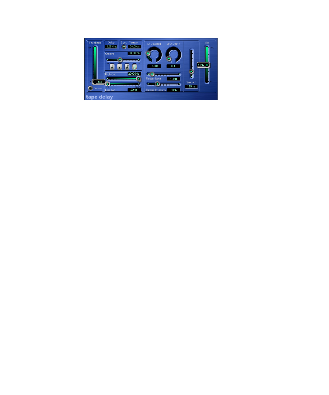
94 Chapter 7 Delay
Tape Delay
The Tape Delay simulates a vintage tape echo device, although with some very useful
features that such old devices never offered. The first of these is that it’s delay settings
are variable in musical increments. It is equipped with a highpass and lowpass filter in
the feedback circuit, as well as a circuit that simulates tape saturation effects. This plugin is ideal for the dub delays invented by Jamaican toast masters, and used in many
styles of music today.
Switching the Sync button on forces the plug-in to use the internal tempo of the
sequencer. Tempo information is updated in the plug-in window when you open it,
and every time you subsequently execute a mouse operation. The plug-in can even
handle tempo changes. The Tempo parameter field serves solely to display the current
bpm value—you can’t use it to change the tempo of the sequencer.
When you want to create dotted note values, move the Groove slider all the way to the
right to 75%; for triplets, select the 33.33% setting. Note that all intermediate values are
possible. You can view the current delay value in the Delay parameter field.
Disengage Sync if you would like to adjust the delay time independently of the song
tempo (or change the song tempo without changing the delay time). In this mode, the
bpm or ms values can be altered freely by clicking in the Tempo parameter field, while
dragging up or down with the mouse. Note when changing the ms values using the
left portion of the Delay parameter field, the ms values will increment in large steps,
while using the right portion of the field will increment the ms values in small steps.
As you might expect, the Feedback slider determines feedback intensity; in other words,
the amount of delayed and filtered signal that is routed back to the input of the Tape
Delay. When you set it to the lowest possible value, the Tape Delay generates a single
echo. If Feedback is turned all the way up, the echoes are repeated ad infinitum. Keep
in mind that the levels of the original signal and its taps (echo repeats) tend to add up,
and may cause distortion. This is where the internal tape saturation circuit comes to the
rescue—it can be used to ensure that these overdriven signals sound good.
The Freeze parameter captures the current delay repeats and sustains them until the
Freeze parameter is released.
Page 95

Chapter 7 Delay 95
You can shape the sound of the echoes, using the on-board highpass and lowpass
filters. Although these filters are fairly flat, they’re not located post-output. They are
located in the feedback circuit, meaning that the effect achieved by these filters
increases in intensity with each repeat. If you’re in the mood for an increasingly muddy
tone, move the High Cut filter slider towards the left. For ever thinner echoes, move the
Low Cut filter slider towards the right.
The Mix slider determines the balance between the original (dry) signal and effects
(wet) signals. If you’ve inserted the Tape Delay in an individual track, you’ll generally
find that settings of up to 50% are desirable. If the Tape Delay is patched to the insert
of a Bus channel, and you’re routing the signals of a track to the plug-in with the Send
controls, you should set the Mix slider to 100%, and leave it there.
If you’re unable to hear the effect, even though you’ve set up a suitable configuration,
be sure to check out not only the Mix knob, but also the filter settings: Move the High
Cut filter slider to the far right, and the Low Cut filter slider to the far left.
The Tape Delay includes an LFO for delay time modulation. Use it to produce very
pleasant and special chorus effects, even on long delays. The LFO produces a triangular
wave, with adjustable speed and modulation intensity, that can be evened out with the
Smooth parameter. This also smoothes the Flutter. Flutter simulates the irregularities of
tape transport speeds used in analog tape delay units, and is also adjustable in speed
and intensity.
There are three further parameters in the Tape Delay’s Controls view. The Dry and Wet
sliders can be used to control the original and effect signal amounts individually,
independently of the Mix parameter. Distortion Level can lower the distorted signal
(tape saturation) level by up to 20 dB.
Page 96
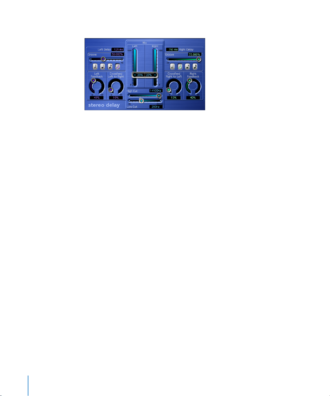
96 Chapter 7 Delay
Stereo Delay
The Stereo Delay works much like the Tape Delay, which is why we’ll skip the general
info, and take a closer look at the differences between the two. There is just one Stereo
Delay (s/s), hence the stereo input and output. You are free to use the Stereo Delay for
monaural tracks or busses, when you want to create independent delays for the two
stereo sides. Please bear in mind that if you use this option, the track or bus has two
channels from the point of insertion forward. Unlike the Tape Delay, the Stereo Delay
does not feature a circuit that replicates tape saturation.
You can set the Delay (using Note buttons and Groove sliders), Feedback, and Mix
values separately for the two sides. The High Cut and Low Cut sliders, however, apply
equally to both sides. In addition, the plug-in features a Crossfeed knob for each stereo
side. It determines the feedback intensity—or the level at which each signal is routed
to the opposite stereo side.
There are ten additional parameters in the Stereo Delay’s Controls view.
If you would like to adjust the delay time independently of the song tempo, select ms
in the Delay Unit pull-down menu. You can use the Left Delay and Right Delay sliders just
above the Delay Unit pull-down menu to set the delay time in milliseconds. Left Input
and Right Input determine the input signal for the two stereo sides. You can choose
between Off, Left, Right, L+R, L−R.
Selecting the Inv option in the Phase Left FB and Phase Right FB pull-down menus allows
you to invert the phase of the corresponding channel’s feedback signal. The inv option
is also available in the Phase L→R FB and Phase R→L FB pull-down menus, where it can
be used to transfer the inverted feedback signal of the left/right channel to the right/
left channel. The Tempo Freeze parameter captures the current delay time and sustains
it until the Freeze parameter is released.
Page 97
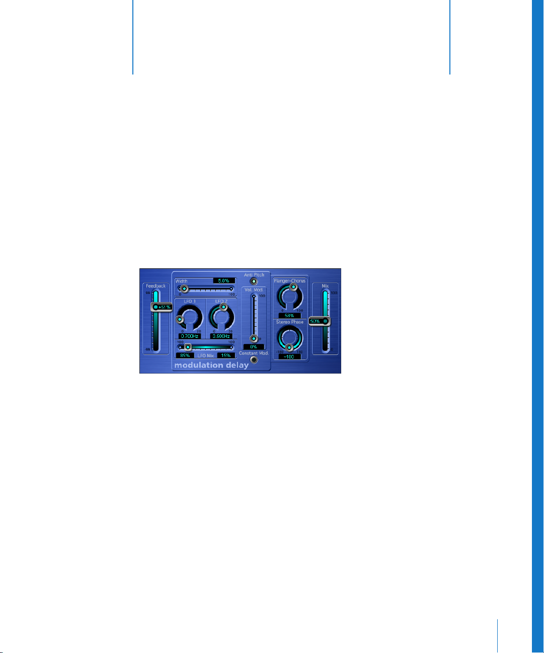
8
97
8 Modulation
This chapter introduces Logic’s modulation effects.
This includes the Modulation Delay, Chorus, Flanger, Phaser, Ring Modulator, Tremolo,
Ensemble, Rotor Cabinet, Scanner Vibrato, and Spreader plug-ins.
Modulation Delay
As its name implies, the Modulation Delay generates effects such as flanging or chorus,
based on modulated short delays. It can also be used—without modulation—to create
resonator or doubling effects.
The modulation section consists of two LFOs, with variable frequencies (0 to 20 Hz). The
balance between these two is determined by the LFO Mix slider. Use the Width slider to
enter the desired modulation width. When the Width slider is set to the far right
position, delay modulation is switched off completely. The Vol.Mod. (Volume
Modulation) slider determines the intensity of amplitude modulation (Tremolo). The
Constant Mod. (Constant Modulation) button lets you do just that—ensure that the
modulation width remains constant, regardless of the modulation rate. When this
feature is switched off, higher modulation frequencies reduce the modulation width. In
simple delay circuits, a delay modulation would normally also modulate the pitch of
the signal. Use the Anti Pitch button to ensure that the pitch of the modulated signal
remains constant. This is exactly how high-end chorus and flanger effects work.
Page 98
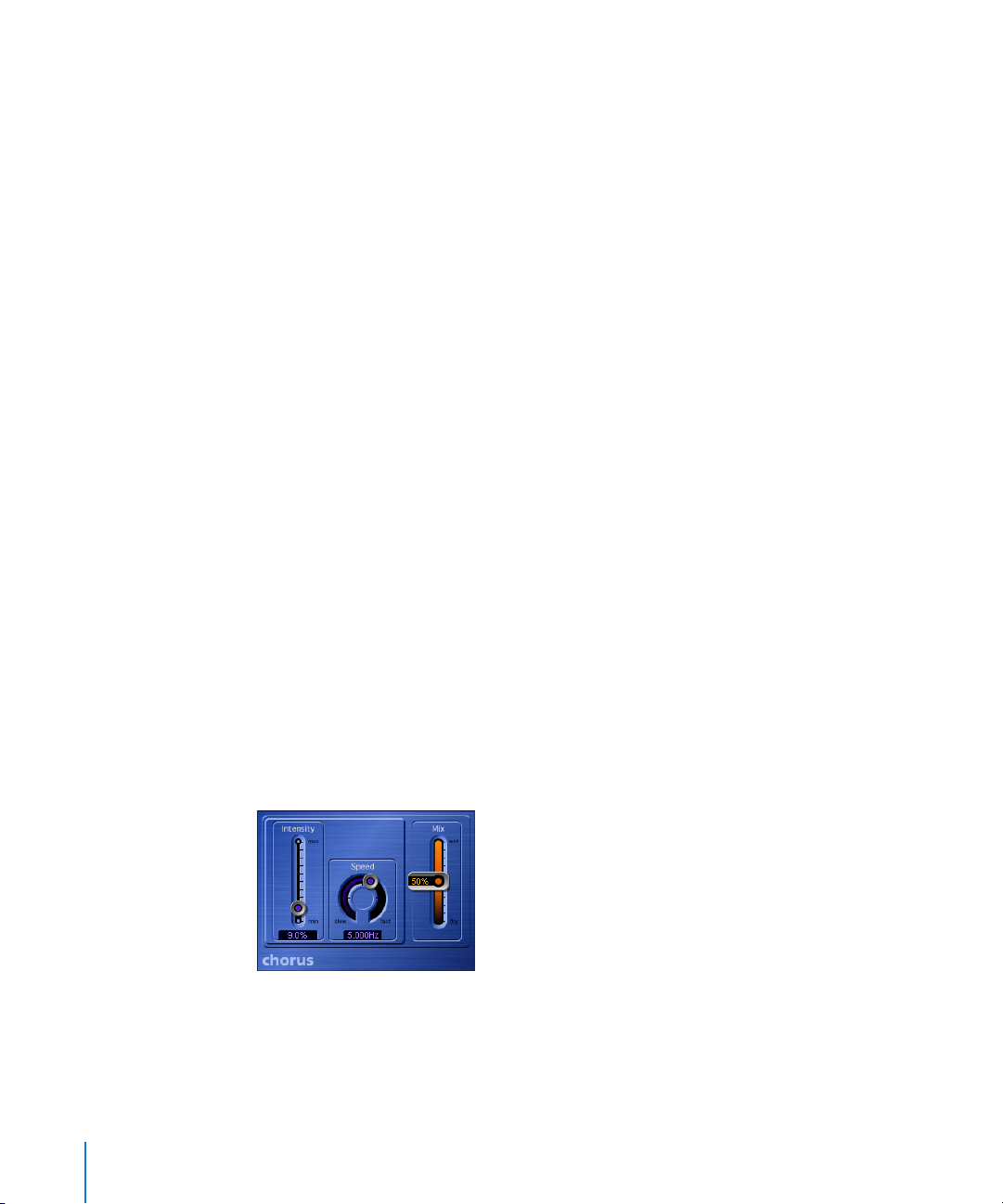
98 Chapter 8 Modulation
Set the basic delay time with the Flanger-Chorus knob. Set to the far left position, the
Modulation Delay puts on its flanger cap. As you move towards the center position, it
thinks it’s a chorus. As you move the knob closer to the far right position, you will hear
clearly audible delay taps. This latter type of setting is generally used without
modulation (Width = 0), for doubling effects.
The Stereo Phase knob defines the phase of the modulation between the left and right
stereo sides. At 0°, the extreme values of the modulation are achieved simultaneously
on both sides, at 180°, the extreme values opposite each other are reached
simultaneously.
The Feedback slider determines the intensity at which the effect’s signal feedback is
routed to the input. If you’re going for radical flanging effects, enter a high Feedback
value. If simple doubling is what you’re after, you won’t want any feedback at all. The
Mix slider determines the balance between dry and wet signals.
The Controls view offers six further parameters:
If you set True Analog to on, an additional all-pass filter is switched into the signal path.
An all-pass filter shifts a signal’s phase angle, influencing its stereo image. Use Analog
Left and Analog Right to control the way that the allpass filter affects each of the stereo
channels.
The Speed LFO 1 R and Speed LFO 2 R sliders allow independent modulation rate settings
for LFO1 and 2 (for the right stereo channel). These parameters only work if the Free
option is chosen in the Stereo pull-down menu. With Stereo set to Link, the modulation
rates of the left and right stereo channels are tied to each other, and rates are set by
the LFO controls in the Plug-in window. In this situation, the Speed LFO 1 R and Speed
LFO 2 R parameters are non-functional.
Chorus
The Chorus effect is based on a delay line. It’s output is mixed with the original, dry
signal. While the chorus effects delay time is set internally, you can define its
modulation width (Intensity parameter) and modulation frequency (Speed parameter).
The Mix slider determines the balance of dry and wet signals.
Page 99
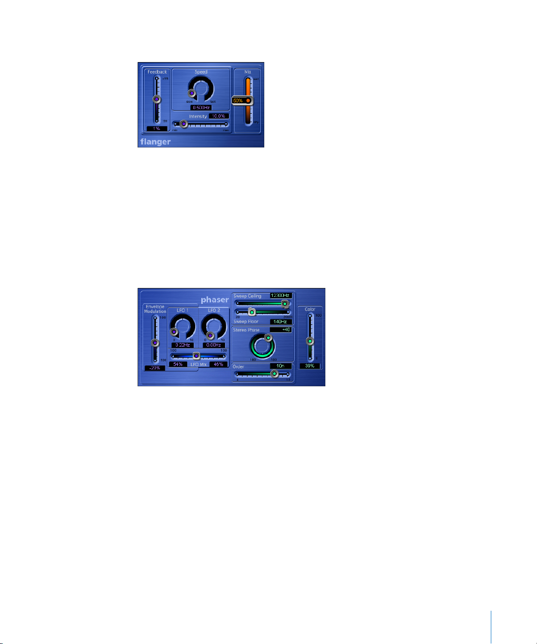
Chapter 8 Modulation 99
Flanger
The Flanger works in a similar fashion to the Chorus, but with a shorter delay time, and
the output signal being fed back into the input of the delay line. Use the Intensity slider
to determine the Flanger’s modulation width. Speed sets the frequency of the
modulation. Feedback determines the amount of the delayed signal that is routed back
into the input. Negative values invert the phase of the routed signal. The Mix slider
determines the balance of dry and wet signals.
Phaser
The Phaser emulates the effect of analog phaser circuits with four to twelve orders (as
in 4th order, 5th order and so on) Use the Order slider to set the desired number of
orders. As a rule, the more orders a phaser has, the heavier the effect. The 4, 6, 8, 10,
and 12 settings put five different phaser algorithms at your fingertips, all of which
replicate the analog circuits that they are modeled on, each designed for a specific
application.
Note: You are free to select odd numbered settings (5, 7, 9, 11), which, strictly speaking,
don’t generate actual phasing. The more subtle comb filtering effects produced by odd
numbered settings can, however, come in handy on occasion.
Page 100

100 Chapter 8 Modulation
The modulation section offers two LFOs, featuring individually variable frequencies, and
freely variable mix options (LFO Mix). Additionally, the frequency of LFO 1 can be
modulated by the level of the input signal. Use the Envelope Modulation slider to set
the desired modulation intensity. By staking out the limits of the modulation with its
highest and lowest values, you can determine the modulation width and range. These
high/low limits are controlled by the Sweep Ceiling and Sweep Floor sliders—you can
enter values for them directly in the form of the desired frequency. This value also
determines the maximum intensity of the comb filtering created by the phasing effect.
The Stereo Phase knob is used to define the phase for the left and right channels of a
stereo phaser (s/s). When you’re using a monaural phaser, this parameter is, of course,
meaningless and can’t be set. As the icing on the phasing cake, you can tweak the
Color slider to add just that to the effect. Technically, the comb filtering effect is
amplified via feedback.
There are six additional parameters in the Phaser’s Controls view.
The Mix slider determines the balance of dry and wet signals. Negative values result in
a phase inverted mix of effect and direct signal. The Phaser’s built-in envelope follower
tracks any volume changes in the input signal, generating a dynamic control signal.
This control signal can be used as a modulation source. Dir.-Env-Mod sets the desired
modulation intensity for the envelope control signal. Warmth switches on an additional
distortion effect, which allows the creation of warm overdrive effects. FB Filter can be
used to activate an additional filter section, which processes the feedback signal of the
Pitch Shifter. This filter section consists of a highpass and lowpass filter, where cutoff
frequency can be set with LP Cutoff and HP Cutoff.
 Loading...