

For Residential and Commercial Applications
ES-LFN55B
Job Name
Job Location
Engineer
Approval
–––––––––––––––––––––––––––––––––––––––––––
–––––––––––––––––––––––––––––––––––––––––
–––––––––––––––––––––––––––––––––––––––––––––
–––––––––––––––––––––––––––––––––––––––––––––
LEAD FREE
*
Contractor
Approval
Contractor’s P.O. No.
Representative
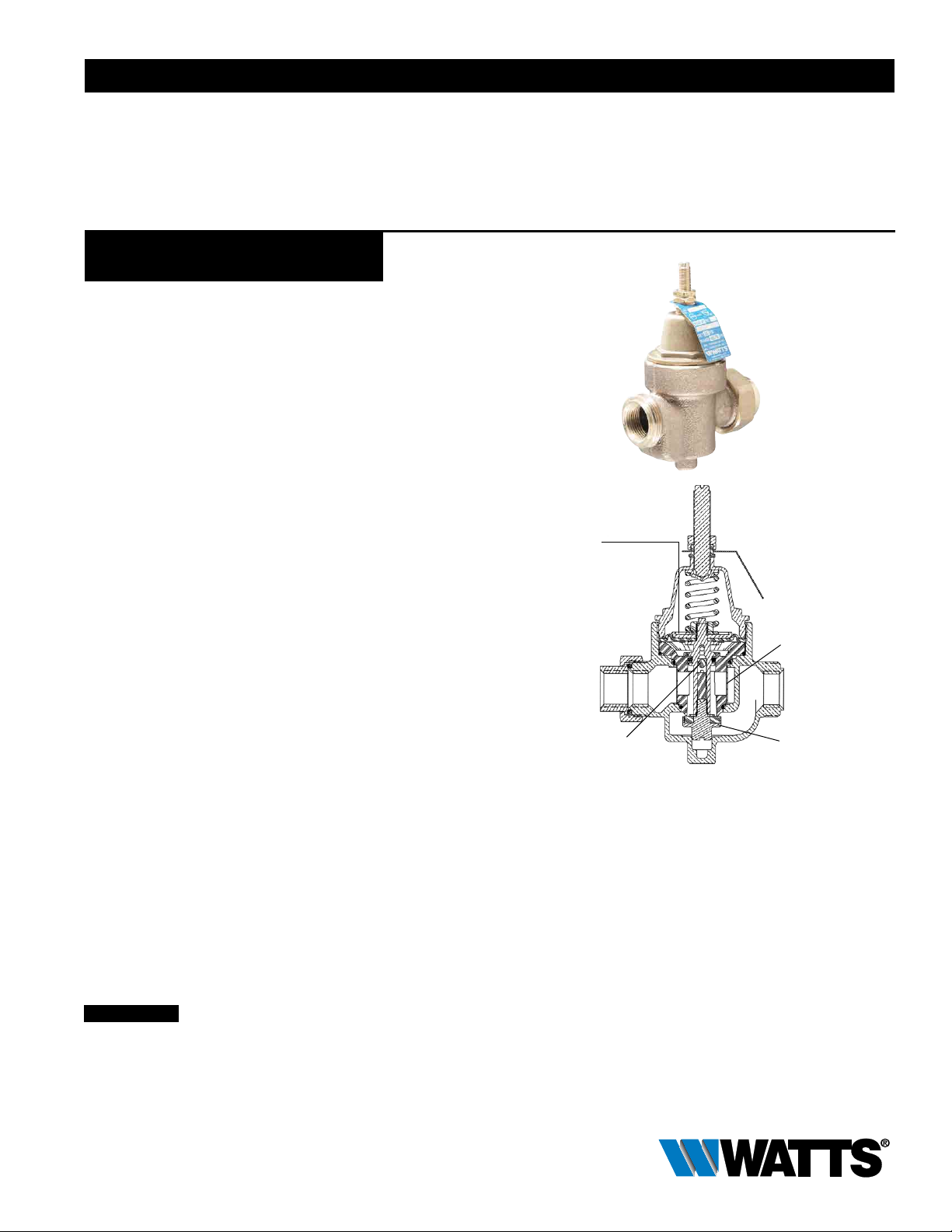
Series LFN55B-M1
Water Pressure Reducing Valves**
Sizes: 1⁄2" – 1"
Series LFN55B-M1 Water Pressure Reducing Valves are
designed to reduce incoming water pressure to a sensible level
to protect plumbing system components and reduce water
consumption. The LFN55B features Lead Free* construction to
comply with Lead Free* installation requirements. This series is
suitable for water supply pressures up to 400psi (27.6 bar) and
may be adjusted from 25 to 75psi (172 – 517 kPa). The standard
setting is 50psi (345 kPa). All parts are quickly and easily serviceable without removing the valve from the line. The standard
bypass feature permits the flow of water back through the valve
into the main when pressures, due to thermal expansion on the
outlet side of the valve, exceed the pressure in the main supply.
––––––––––––––––––––––––––––––––––––––––––––
–––––––––––––––––––––––––––––––––––––––––––––
––––––––––––––––––––––––––––––––––
––––––––––––––––––––––––––––––––––––––––
LFN55BU-M1
Reinforced
Diaphragm
Features
• Integral stainless steel strainer
• Thermoplastic seat
• Lead Free* brass body construction
• Serviceable in line
• Bypass feature controls thermal expansion pressure***
• Sealed spring cage on all models for accessible outdoor or pit
installations
Specifications
Standard Specifications: A Water Pressure Reducing Valve with
integral strainer shall be installed in the water service pipe near
its entrance to the building where supply main pressure exceeds
60psi (413 kPa) to reduce it to 50psi (345 kPa) or lower. The
water pressure reducing valve shall be constructed using Lead
Free* materials. Lead Free* regulators shall comply with state
codes and standards, where applicable, requiring reduced lead
content. The valve shall feature a Lead Free* brass body suitable
for water supply pressures up to 400psi (27.6 bar). Provision
shall be made to permit the bypass flow of water back through
the valve into the main when pressures, due to thermal expansion on the outlet side of the valve, exceed the pressure in the
main supply. Water Pressure Reducing Valve with builtin bypass
check valves will be acceptable. Approved valve shall be listed to
ASSE 1003 and IAPMO and certified to CSA B356. Valve shall
be a Watts Series LFN55B-M1.
NOTICE
The information contained herein is not intended to replace the full
product installation and safety information available or the experience of a trained product installer. You are required to thoroughly
read all installation instructions and product safety information
before beginning the installation of this product.
Integral Stainless
Steel Strainer
Thermal
Expansion Bypass
Thermoplastic
Seat
Materials
Body: Lead Free* brass
Seat: Thermoplastic
Cage: Bronze
Integral Strainer: Stainless steel
Diaphragm: Reinforced EPDM
Valve Disc: Elastomer
* The wetted surface of this product contacted by consumable
water contains less than 0.25% of lead by weight.
** A water saving test program concluded that reducing the
supply pressure from 80-50psi (551-345 kPa) resulted in a
water savings of 30%.
*** The bypass feature will not prevent the pressure relief valve
from opening on the hot water supply system with pressure
above 150psi (10.3 bar).
Watts product specifications in U.S. customary units and metric are approximate and are provided for reference only. For precise measurements,
please contact Watts Technical Service. Watts reserves the right to change or modify product design, construction, specifications, or materials without prior notice and without incurring any obligation to make such changes and modifications on Watts products previously or subsequently sold.

Pressure — Temperature
Temperature Range: 33°F – 180°F (0.5°C – 82°C)
Maximum Working Pressure: 400psi (27.6 bar)
Adjustable Reduced Pressure Range:
25 – 75psi (172 – 517 kPa)
Standard Reduced Pressure Setting: 50psi (345 kPa)
Capacity
kPa psi
0 0
34.5 5
Standards
Meets requirements of ASSE Standard 1003; (ANSI A112.26.2)
and CSA Standard B356. Certified by NSF to ANSI/NSF
Standard 61-G. Listed by IAPMO.
Options
Add Suffix
-“ “ NPT threaded female inlet x NPT female outlet
-U NPT threaded union inlet x NPT female outlet
-U-S Solder union inlet x NPT female outlet
-w/press**** Press inlet x press outlet (non union)
-DU Double Union - NPT threaded union female inlet
and outlet
-DU-S Double Union - Solder union inlet and outlet
-DU-PEX Double Union - PEX union inlet and outlet
-DU-CPVC Double Union - CPVC union inlet and outlet
-G Gauge tapping,
1
⁄8" (3mm)
-LP Low pressure range 10-35psi (69 - 241 kPa)
**** Viega ProPress
®
connections are optional factory installed
fittings on each end of the approved/certified assembly.
Dimensions – Weights
68.9 10
103.4 15
Pressure Drop
137.8 20
172.3 25
0 10 20 30 40 gpm
0 37.3 75.7 113.6 151.4 lpm
Flow
FNPT
ENPT
FSWEAT
ESWEAT
FPEX
C
FEMALE NPT THREAD
BOTH ENDS OF BODY
EPEX
FCPVC
D
ECPVC
A
A + E
ABOVE VALVE SHOWN WITH SINGLE NPT UNION CONNECTION ON INLET
VALVES MAY BE ORDERED WITH 0,1,OR 2 UNION CONNECTIONS USING ANY
COMBINATION OF NPT, SOLDER, PEX OR CPVC CONNECTIONS REQUIRED
“F” DIMENSIONS ARE APPROXIMATE ENGAGEMENT LENGTHS.
SIZE DIMENSIONS WEIGHT
A C D ENPT ESWEAT EPEX ECPVC EQC FNPT FSWEAT FPEX FCPVC FQC G
in. in. mm in. mm in. mm in. mm in. mm in. mm in. mm in. mm in. mm in. mm in. mm in. mm in. mm in. mm lbs. kgs.
1
⁄2 37⁄16 88 49⁄16 116 111⁄16 435⁄8 165⁄8 1513⁄16 219⁄16 15 17⁄16 361⁄2 131⁄2 135⁄8 161⁄2 13 11⁄2 38 21⁄4 57 2 .91
3
⁄4 37⁄16 88 49⁄16 116 111⁄16 435⁄8 167⁄8 2115⁄16 2413⁄16 21 19⁄16 409⁄16 143⁄4 195⁄8 163⁄4 18 111⁄16 42 21⁄4 57 2 .91
1
1 4
⁄8 105 49⁄16 116 111⁄16 433⁄4 20 1 26 11⁄8 29 11⁄16 26 111⁄16 4311⁄16 1715⁄16 2313⁄16 2115⁄16 23 13⁄4 45 21⁄4 57 3 1.36
A + E + E
G
FQC
EQC
Consult factory for dimensions with press connections.
USA: T: (978) 689-6066 • F: (978) 975-8350 • Watts.com
Canada: T: (905) 332-4090 • F: (905) 332-7068 • Watts.ca
Latin America: T: (52) 81-1001-8600 • F: (52) 81-8000-7091 • Watts.com
ES-LFN55B 1640 © 2016 Watts
 Loading...