

Page 1
INSTALLATION, OPERATION & MAINTENANCE MANUAL
BACKFLOW
BFMM DC4A SBF | EFFECTIVE AUGUST 1, 2016
Model DC4A / DCLF4A
1/2” - 2”
Double Check Valve (DC)
Backflow Preventer
Page 2

INSTALLATION, OPERATION, & MAINTENANCE MANUAL
TABLE OF CONTENTS
Double Check Valve Backow Preventer 1/2” – 2”
Section Page
I Description and Operation ......................................................................3
II Installation .....................................................................................3
III Trouble Shooting Guide.........................................................................5
IV Maintenance Instructions .......................................................................5
V Testing Procedures............................................................................6-7
Parts List
Parts List (1/2”- 2”) .......................................................................... 8-10
Repair Kits
Repair Kits (1/2”- 2” ) ..........................................................................11
2
www.apollovalves.com Customer Service (704) 841-6000
Page 3

BFMM DC4A SBF
DOUBLE CHECK VALVE BACKFLOW PREVENTER 1/2” 2”
I. DESCRIPTION AND OPERATION
The Double Check Valve (DC) device consists of two independently-acting, spring-loaded check valves. Two resilient seated shuto valves and four test cocks complete the assembly. Each check is designed to maintain a minimum of 1 psi across the valve
during normal operation. If at any time the pressure downstream of the device increases above the supply pressure, both check
valves will close to prevent any backow from occurring. The owing and no ow conditions are illustrated in gures 1 and 2.
To initiate ow, supply pressure must be sucient to open both checks and overcome friction, normally a minimum of 3 to 5 psi
above the downstream pressure.
II. INSTALLATION
A. The DC must be installed in an accessible location to facilitate periodic eld testing and maintenance.
B. Flush all upstream piping thoroughly to remove foreign matter prior to installing the device.
C. The device should be installed either horizontally or vertical up for ease of maintenance and testing. A clearance between
the lower most portion of the device and ood grade or oor should be provided for ease of maintenance.
D. When shut-o valves are provided separately, they should be installed with a test cock on the upstream side of the inlet shut o valve.
E. After installing the assembly and with downstream or #2 shut-o valve closed, pressurize the device and bleed ALL air
through test cock #4. Then open #2 shut-o valve.
Customer Service (704) 841-6000 www.apollovalves.com
3
Page 4
INSTALLATION, OPERATION, & MAINTENANCE MANUAL
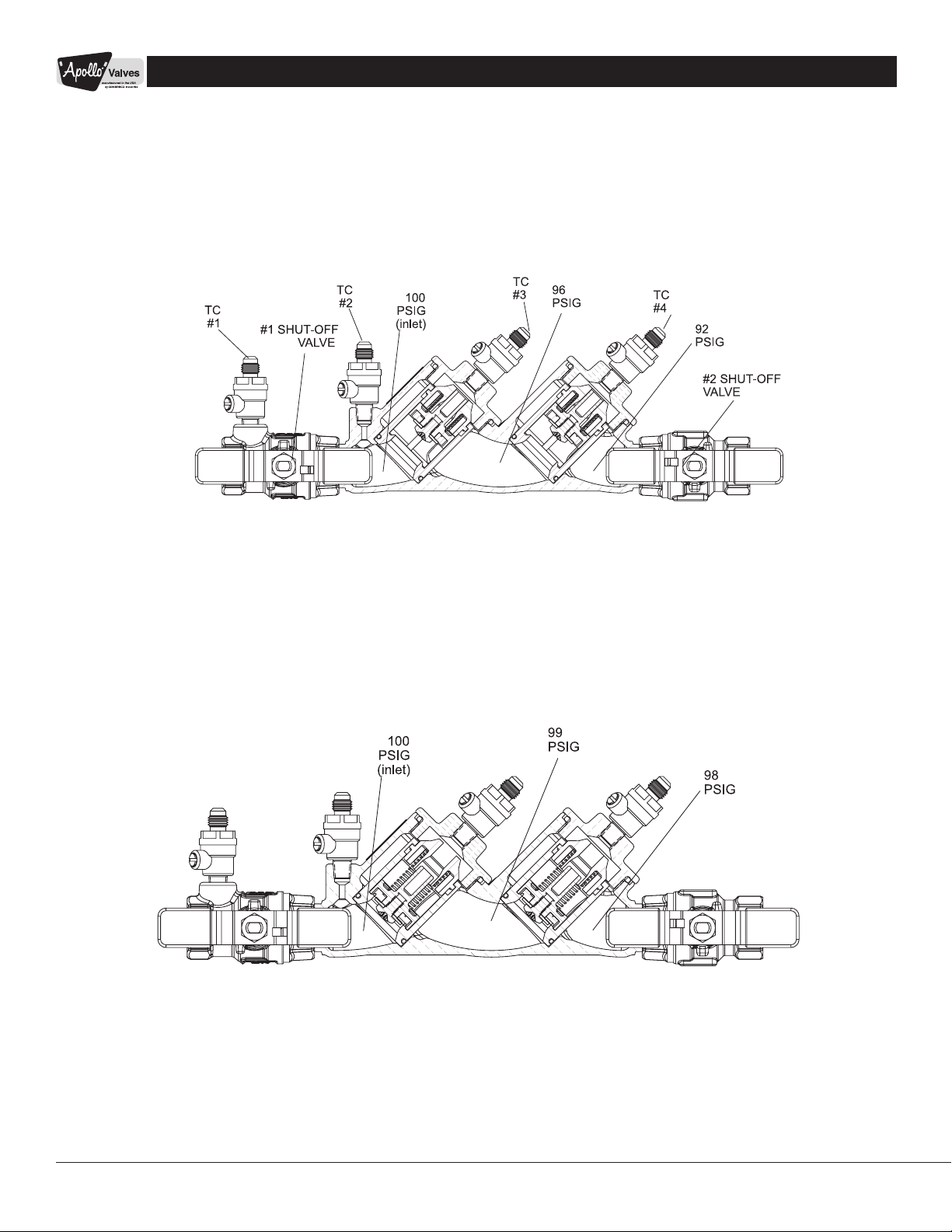
Figure 1
FLOWING CONDITION
Figure 2
NO FLOW CONDITION
NOTE: Pressures shown are for illustrative
purposes only and are not necessarily
indicative of any actual valve.
4
www.apollovalves.com Customer Service (704) 841-6000
Page 5

BFMM DC4A SBF
III. TROUBLE SHOOTING
SYMPTOM CAUSE CORRECTIVE ACTION
1. Check valve fails to hold
1 psid.
IV. MAINTENANCE INSTRUCTIONS 1/2” – 2”
A. Disassembly - Check Valves
1. Close #2 shut-o valve, then close #1 shut-o valve.
2. Bleed pressure from the assembly by opening #2, #3, and #4 test cocks.
3. Unscrew cap using hex head provided.
4. Push down and turn the spring retainer 90 degrees to remove. Remove the spring. Remove the poppet from the check seat.
5. Normally, the check seat need not be removed. If removal is required, rock it back and forth while pulling outward.
a. Shut-o valve not closed
completely.
b. Check valve fouled with
debris.
c. Check poppet stem not
moving freely in guide.
a. Close #2 shut-o valve or
inspect for possible
through leakage.
b. Inspect and clean seat
disc and seat.
c. Inspect for debris or
deposit on poppet stem
or guide.
B. Disassembly - Check Valve Poppet
CAUTION: Do not use pliers or other tools, which may damage or scratch the plastic stem.
1. Holding the poppet assembly in one hand, remove screw and retaining washer.
2. Remove the seat disc.
3. All parts should be carefully inspected for any damage or excessive wear and thoroughly rinsed in clean water prior to
reassembly. Replace worn parts as necessary.
C. Assembly - Check Valve Poppet
1. Install new disc in poppet and secure with washer and screw.
D. Assembly - Check Valve
1. If the check seat was removed, install the new o-ring and lubricate with a thin coat of Apollo supplied lubricant, DOW 111
or equal. Line up the seat with the bore and push it rmly into place.
2. Place and center the poppet assembly in the check seat.
3. Install the spring onto the poppet.
4. Install the spring retainer onto the spring by pushing down into the grooves of the check seat and turning 90 degrees.
Ensure spring retainer pops up about .1” and locks into the lugs. CAUTION: Ensure the spring retainer orientation matches
that in the parts list drawing or the device’s ow will be signicantly restricted.
5. Apply a thin coat of Apollo supplied lubricant, DOW 111 or equal on cap o-ring.
6. Install cap.
Customer Service (704) 841-6000 www.apollovalves.com
5
Page 6

INSTALLATION, OPERATION, & MAINTENANCE MANUAL
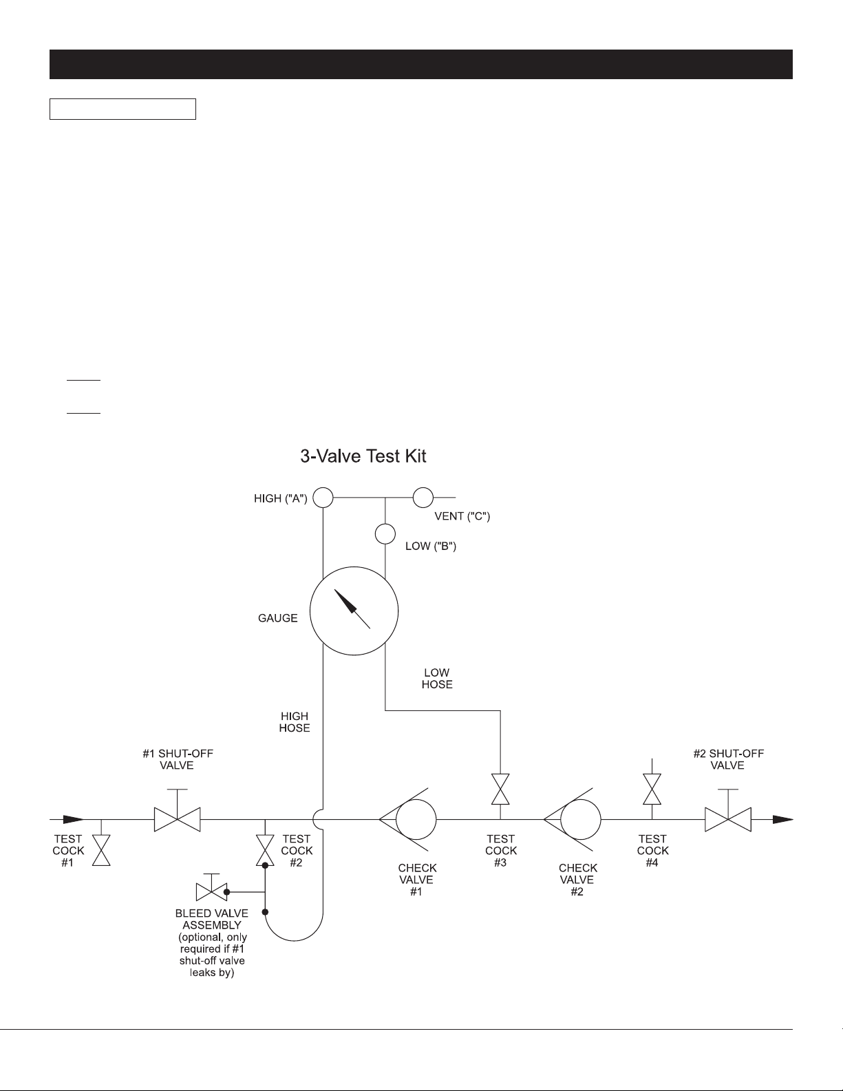
V. TESTING PROCEDURES
This test is performed with the Dierential Pressure Gauge Test Kit. The Dierential Pressure Gauge simply measures the pressure
drop across the check valve. This pressure drop is normally the same as the strength of the check valve spring. In using the
Dierential Pressure Gauge to test the Double Check assembly, a minimum of 1.0 psid is required for each check valve in order
for that check valve to pass the test. Such a small reading is often dicult to read on most test kits. This is one of the drawbacks
of this test. However, since the rst shut-o valve is left in the open position for this test, it is possible to use this test when the
rst shut-o valve is leaking badly.
NOTE: This is a three-valve test kit procedure and may or may not be approved in all jurisdictions. Consult your local water
purveyor for acceptable test procedures.
Test Setup
1. Notify customer that the water service will be o. Identify the make, model, and serial number on the backow device.
Inspect that this is an approved assembly - two check valves, two shut-o valves and four test cocks. Observe the area to
make sure there are no leaks.
2. Flush test cocks (1, 2, 3 & 4), then close all test cocks.
3. Install appropriate adapters (if necessary).
4. Close shut-o valve #2.
TEST NO. 1
PURPOSE: To test check valve #1
1. Close all valves on test kit.
2. Connect the high side hose to test cock #2 and the low side hose to test cock #3. Open test cock #2 and test cock #3.
3. Open vent valve “C” and high “A” on the test kit to bleed air from the high side of the kit. Close high “A” valve and then
open low “B” valve to bleed the low side. Close low “B” valve.
4. Record the gauge reading. It must be a minimum of 1.0 psid in order to pass. Close test cock #2 and test cock #3.
TEST NO. 2
PURPOSE: To test check valve #2
1. Move the high side hose to test cock #3 and the low side hose to test cock #4. Open test cock #3 and test cock #4.
2. Open vent “C” valve. Then open high “A” and bleed air from the high side of the kit. Close high “A” valve, and then open low
“B” valve and bleed the low side of the kit. Close low “B” valve.
3. Record the gauge reading. It must be a minimum of 1.0 psid in order to pass. Close test cock #3 and test cock #4. Remove
hoses and test kit. Slowly open shut-o valve #2 in order to restore water ow to the facility, placing the DC back into service.
6
www.apollovalves.com Customer Service (704) 841-6000
Page 7
BFMM DC4A SBF
TEST NO. 3
PURPOSE: To test leaking #2 shut-o valve
As previously mentioned, the above test is not accurate when the second shut-o valve is leaking. The following test will expose
a leaking shut-o valve.
1. Both shut-o valves should be open. Make sure all valves on test kit are closed. Connect the high “A” hose to test cock #2
and the low “B” hose to test cock #3. Open test cock #2 and test cock #3.
2. Open the high “A” valve and vent “C” valve to bleed air from high side of gauge. Open low “B” valve to bleed air from low side
of gauge. Close valves “A”, “B” and “C” on test kit.
3. Connect the vent hose to test cock #4. Open test cock #4.
4. Close shut-o valve #2. The dierential gauge needle should read at least 1.0 psid in order to pass.
5. Open the high “A” valve and vent “C” valve. This will put back pressure on check valve #2.
6. Close test cock #2.
NOTE: If gauge is steady, then shut-o valve #2 is holding tight. However, if gauge drops to zero psid, then shut-o valve #2 is leaking.
NOTE: If the gauge rises then the #2 shut-o valve is still leaking, but is under backpressure from the facility.
Customer Service (704) 841-6000 www.apollovalves.com
Figure 3
7
Page 8

INSTALLATION, OPERATION, & MAINTENANCE MANUAL
PARTS LIST 1/2” 2”
Figure 4
8
www.apollovalves.com Customer Service (704) 841-6000
Page 9

BFMM DC4A SBF
DC4A and DCLF4A Parts List
Item # Description
1 Body All 1 Consult Factory
2 Label Plate All 1 Consult Factory
3 Label Plate Tacks All 2 I-2614-00
4
4a
5
6 Cap O-Ring All 2 D-4881-00 D-4812-00 D-4884-00 D-4885-00 D-4888-00
7 Check Module O-Ring All 2 D-4880-00 D-4744-00 D-4882-00 D-4884-00 D-4885-00
8 Check S-Assy (see below) All 2 W-9075-05 W-9003-05 W-9074-05 W-9159-05 W-9204-05
Test Cock M x F (81 metal) Std
Test Cock M x F (Lead Free) LF 78LF-290-01 (Optional) 78LF-291-01 (Standard)
Test Cock SAE (81 metal) Std 78-292-01 (Standard) 78-293-01 (Optional)
Test Cock SAE (Lead Free) LF 78LF-292-01 (Standard) 78LF-293-01 (Optional)
Cap (81 metal) Std
Cap (Lead Free) LF F-3847-05 F-3823-05 F-3849-05 F-3851-05 F-3855-05
Std. or
LF
Qt y.
4
2
1/2” 3/4” 1” 1-1/4” 1-1/2” 2”
78-290-01 (Optional) 78-291-01 (Standard)
F-3846-05 F-3822-05 F-3848-05 F-3850-05 F-3854-05
Individual parts are only available for bulk sales. Please refer to the appropriate repair kits on pages 11.
Check Module Sub-Assembly Parts LIst
Item # Description
9 Check Seat All 1 L-7815-00 L-7727-00 L-7813-00 L-7979-00 L-7983-00
10 Screw All 1 B-3279-00 B-1750-00
11 Disc Retaining Washer All 1 E-2372-00 E-2841-00 E-2933-00 E-2860-00 E-2876-00
12 Seat Disc All 1 D-4771-00 D-4743-00 D-4770-00 D-4853-00 D-4873-00
13 Poppet All 1 K-4491-00 K-4471-00 K-4483-00 K-4511-00 K-4512-00
14 Spring All 1 A-2505-00 A-2503-00 A-2510-00 A-2511-00 A-2512-00
15 Spring Retainer All 1 L-7814-00 L-7726-00 L-7812-00 L-7980-00 L-7984-00
Std. or
LF
Qt y.
1/2” 3/4” 1” 1-1/4” 1-1/2” 2”
Individual parts are only available for bulk sales. Please refer to the appropriate repair kits on pages 11.
Part Number
Part Number
Customer Service (704) 841-6000 www.apollovalves.com
9
Page 10

INSTALLATION, OPERATION, & MAINTENANCE MANUAL
Item # Description
T2 Inlet NPT Ball Valve w/ “T”
Handle (Standard)
T4 Inlet Union Ball Valve w/ “T”
Handle (Option)
T2 Inlet NPT Ball Valve w/
Lever Handle (Standard)
T4 Inlet Union Ball Valve with
16
17
Lever Handle (Option)
T2 Inlet NPT Ball Valve with
Locking “T” Handle (Option)
T4 Inlet Union Ball Valve with
Locking “T” Handle (Option)
T2 Inlet NPT Ball Valve with
Locking Lever Handle (Option)
T4 Inlet Ball Union Valve with
Locking Lever Handle (Option)
T2 Outlet NPT Ball Valve with “T”
Handle (Standard)
T4 Outlet Union Ball Valve with
“T” Handle (Option)
T2 Outlet NPT Ball Valve with
Lever Handle (Standard)
T4 Outlet Union Ball Valve with
Lever Handle (Option)
T2 Outlet NPT Ball Valve with
Locking “T” Handle (Option)
T4 Outlet Union Ball Valve with
Locking “T” Handle (Option)
T2 Outlet NPT Ball Valve with
Locking Lever Handle (Option)
T4 Outlet Union Ball Valve with
Locking Lever Handle (Option)
Inlet and Outlet Shut-O Valves
Std. or
LF
81 Mtl
LF 77BLF-103-85 77BLF-104-83 77BLF-105-83
81 Mtl 77B-303-85 77B-304-83 77B-305-83
LF 77BLF-303-85 77BLF-304-83 77BLF-305-83
81 Mtl
LF 77BLF-106-84 77BLF-107-84 77BLF-108-84
81 Mtl
LF 77BLF-306-84 77BLF-307-84 77BLF-308-84
81 Mtl
LF 77BLF-104-91 77BLF-105-91
81 Mtl 77B-304-91 77B-305-91
LF 77BLF-304-91 77BLF-305-91
81 Mtl
LF 77BLF-106-86 77BLF-107-86 77BLF-108-86
81 Mtl
LF 77BLF-306-86 77BLF-307-86 77BLF-308-86
81 Mtl
LF 77CLF-103-85 77CLF-104-83 77CLF-105-83
81 Mtl 77C-303-85 77C-304-83 77C-305-83
LF 77CLF-303-85 77CLF-304-83 77C-305-83
81 Mtl
LF 77CLF-106-84 77CLF-107-84 77CLF-108-84
81 Mtl
LF 77CLF-306-84 77CLF-307-84 77CLF-308-84
81 Mtl
LF 77CLF-104-91 77CLF-105-91
81 Mtl 77C-304-91 77C-305-91
LF 77CLF-304-91 77CLF-305-91
81 Mtl
LF 77CLF-106-86 77CLF-107-86 77CLF-108-86
81 Mtl
LF 77CLF-306-86 77CLF-307-86 77CLF-308-86
Qt y.
1/2” 3/4” 1” 1-1/4” 1-1/2” 2”
77B-103-85 77B-104-83 77B-105-83
Not Available
Not Available
1
Not Available
77C-103-A4 77C-104-83 77C-105-83
1
Not Available
77B-104-91 77B-105-91
Not Available
Not Available
Not Available
Not Available
77C-104-91 77C-105-91
Not Available
Not Available
Part Number
Not Available
Not Available
77B-106-84 77B-107-84 77B-108-84
77B-306-84 77B-307-84 77B-308-84
Not Available
Not Available
77B-106-86 77B-107-86 77B-108-86
77B-306-86 77B-307-86 77B-308-86
Not Available
Not Available
77C-106-84 77C-107-84 77C-108-84
77C-306-84 77C-307-84 77C-308-84
Not Available
Not Available
77C-106-86 77C-107-86 77C-108-86
77C-306-86 77C-307-86 77C-308-86
Replacement Handles for Ball Valve Shut-O Valves (T2 & T4 options)
“T” Handle
Lever Handle Not Available W-9366-00
Locking “T” Not Available W-2394-00 Not Available
Locking Lever Not Available W-9686-00
All
W-9732-00 W-9864-00 W-9734-00
Stainless steel handles are standard on all Apollo® backow devices.
10
www.apollovalves.com Customer Service (704) 841-6000
Page 11

BFMM DC4A SBF
REPAIR KITS DC4A & DCLF4A 1/2” 2”
Check Module Rubber Kit (One kit repairs one check)
(Universal, for standard & lead free valves)
Repair Kit Model Number RK4A12CMR RK4A34CMR RK4A1CMR RK4A112CMR RK4A2CMR
Item # Ordering Number 4A-003-01 4A-004-01 4A-005-01 4A-007-01 4A-008-01
not Shown O-Ring Lubricant I-9016-00
11 Check Module Seat Disc 1 D-4771-00 D-4743-00 D-4770-00 D-4853-00 D-4873-00
7 Check Module O-Ring 1 D-4880-00 D-4744-00 D-4882-00 D-4884-00 D-4885-00
6 Cap O-Ring 1 D-4881-00 D-4812-00 D-4884-00 D-4885-00 D-4888-00
DC Checks Complete Kit (One kit repairs one check)
(Universal, for standard & lead free valves)
Repair Kit Model Number RK4A12CMC RK4A34CMC RK4A1CMC RK4A112CMC RK4A2CMC
Item # Ordering Number 4A-003-02 4A-004-02 4A-005-02 4A-007-02 4A-008-02
not Shown O-Ring Lubricant I-9016-00
8 Check Module S-Assy 1 W-9075-05 W-9003-05 W-9074-05 W-9159-05 W-9204-05
7 Check Module O-Ring 1 D-4880-00 D-4744-00 D-4882-00 D-4884-00 D-4885-00
6 Cap O-Ring (for DC/RP) 1 D-4881-00 D-4812-00 D-4884-00 D-4885-00 D-4888-00
extra part(s) Bonnet O-Ring (for PVB) 1 D-4812-00 D-4883-00 D-4887-00 D-4858-00
DC Complete Internals Kit (One kit repairs ONE DC valve)
(Universal, for standard & lead free valves)
Repair Kit Model Number RK4A12TDC RK4A34TDC RK4A1TDC RK4A112TDC RK4A2TDC
Item # Ordering Number 4A-003-08 4A-004-08 4A-005-08 4A-007-08 4A-008-08
not Shown O-Ring Lubricant I-9016-00
8 Check Module S-Assy 2 W-9075-05 W-9003-05 W-9074-05 W-9159-05 W-9204-05
7 Check Module O-Ring 2 D-4880-00 D-4744-00 D-4882-00 D-4884-00 D-4885-00
6 Cap O-Ring 2 D-4881-00 D-4812-00 D-4884-00 D-4885-00 D-4888-00
QTY
QTY
QTY
1/2” 3/4” 1” 1-1/4” – 1-1/2” 2”
1/2” 3/4” 1” 1-1/4” – 1-1/2” 2”
1/2” 3/4” 1” 1-1/4” – 1-1/2” 2”
Size
Size
Size
Customer Service (704) 841-6000 www.apollovalves.com
11
Page 12

Regional Management List now available online at http://conbra.co/rmlist
704.841.6000
CUSTOMER SERVICE
www.apollovalves.com www.elkhartproducts.com
BFMMDC4ASBF 07/16 1,500 iTek
800.395.7313
CUSTOMER SERVICE
800.776.2756
CUSTOMER SERVICE
www.lascottings.com
 Loading...