


86R-100 SERIES
STAINLESS STEEL 3-PIECE FULL PORT BALL VALVE
W/ ACTUATOR READY ISO MOUNTING PAD
1-1/2” & 2”
Full Port Threaded, 800 CWP (psig), Cold Non-Shock. 150 psig Saturated Steam.
Vacuum Service to 29 inches Hg.
MSS SP-110 Compliant.
Meets NACE MR0175 (2000) & MR0103 (2012)
FEATU R ES
• Multi-piece packing set
• ISO 5211 mounting pad
• Blowout-proof stem design
• In-line repairable
STANDARD MATERIAL LIST
PART MATERIAL
Stem A276-316
1
Jam nut SS
2
Low profile nut 316 SS
3
Gland A276-3 16
4
Stem bearing RPTFE
5
End cap (2) ASTM A351- CF3M
6
Hex nut (4) 18-8 SS
7
Seat (2) RPTFE
8
Ball 316 SS
9
Body bolt (4) 18-8 SS
10
Stem packing MPTFE
11
Body ASTM A351-CF8 M
12
Lock tab washer 304 SS
13
Lever and grip 304 SS w/ Vinyl
14
• Adjustable packing gland
• Investment cast components
• Reinforced seats and seals
• Full port configuration
OPTIONS AVAILABLE
(MORE INFORMATION IN SECTION J)
• Minimum quantities apply
• To specify an option, replace the “0 1” sta ndard s ux with the sux of the optio n.
• To specify multiple options, rep lace the “ 01” sux with the desire d suxes in the
numer ical order shown below. NOT E: Not all suxes c an be com bined togethe r.
(SUFFIX) OPTION SIZES
-01 Standard Configuration All
-P -01 - BSPP (Parallel) Thread Connection All
-T -01- BSPT (Tapered) Thread Connection All
-02- Static Grounded All
-04- 2-1/4” Stem Extension (Carbon Steel, Zinc Plated) All
-08- 90° Reversed Stem All
-14- Vented Ball All
-18- Plain Yellow Grip All
-21- UHMWPE Seats (Non- PTFE) All
-24- Graphite Packing All
-27- Latch Lock Lever All
-35- PTFE Trim All
-36- SS Stainless Steel Locking Round Handle All
-39- SS Hi-Rise Locking Wheel Handle, SS Nut All
-49- No Lubrication. Assembled Dry All
-57- Oxygen Cleaned All
-60- Grounded Ball & Stem All
-63- Threaded x Socket Weld All
-AR- Less Handle & Stop - Add Belleville Washers All
-WB- With Lever & Belleville Washers All
Pressure/Temperature Ratings - Page M-12, Graph No. 8
DIMENSIONS
PART NO. SIZE A B C D E F G H I J (F LATS) K (THREADS.)UNF L
86R-107- 01 1-1/2” 1.50 2.59 5.18 3.49 8.00 0.98 1.95 1.16 0.34 .370/.372 5/8-18 4.35
86R-108-01 2” 2.00 3.01 6.03 3.95 8.06 0.98 1.95 1.16 0.34 .370/.372 5/8-18 4.85
Customer Service (704) 841-6000 industrial.apollovalves.comB-68

86R-100 SERIES
STAINLESS STEEL 3-PIECE FULL PORT BALL VALVE
W/ ACTUATOR READY ISO MOUNTING PAD
3”
Full Port Threaded, 800 CWP (psig), Cold Non-Shock. 150 psig Saturated Steam.
Vacuum Service to 29 inches Hg.
MSS SP-110 Compliant.
Meets NACE MR0175 (2000) & MR0103 (2012)
FEATU R ES
• Multi-piece packing set
• ISO 5211 mounting pad
• Blowout-proof stem design
• In-line repairable
STANDARD MATERIAL LIST
PART MATERIAL
Body ASTM A351-CF8 M
1
End Caps (2) ASTM A351 -CF8M
2
Ball 316 SS
3
Stem A276-316
4
Packing Gland 316 SS
5
Stem Seal MPTFE
6
Seats (2) RPTFE
7
Gland Screws (2) Stainless Steel
8
Gland Plate Stainless Steel
9
Adapter Screw Stainless Steel
10
Handle Adapter Stainless Steel
11
Stem Bearing RPTFE
12
Stops (2) Stainless Steel
13
Stop Screws (2) Stainless Steel
14
Lock Plate Stainless Steel
15
Grounding Spring Stainless Steel
16
Body Bolts (6) Stainless Steel
17
Heavy Hex Nuts (6) Stainless Steel
18
Body Seals (2) RPTFE
19
Seat Holders (2) Stainless Steel
20
Pipe Handle (not shown)
21
• Adjustable packing gland
• Investment cast components
• Reinforced seats and seals
• Full port configuration
OPTIONS AVAILABLE
(MORE INFORMATION IN SECTION J)
• Minimum quantities apply
• To specify an option, replace the “0 1” sta ndard s ux with the sux of the optio n.
• To specify multiple options, rep lace the “ 01” sux with the desire d suxes in the
numer ical order shown below. NOT E: Not all suxes c an be com bined togethe r.
(SUFFIX) OPTION SIZES
-01 Standard Configuration All
-02- Static Grounded All
-14- Vented Ball All
-24- Graphite Packing All
-35- PTFE Trim All
-49- No Lubrication. Assembled Dry All
-57- Oxygen Cleaned All
-60- Grounded Ball & Stem All
-63- Threaded x Socket Weld All
Pressure/Temperature Ratings - Page M-12, Graph No. 8
DIMENSIONS
PART NO. SIZE A B C D E F G H I J (FLATS) K L (THREADS.)UNF
86R-100-01 3” 3.00 4.00 8.00 8.80 4.75 5.94 0.50 1.420 2.840 0.725 1.250 3/8-16
Customer Service (704) 841-6000 industrial.apollovalves.com B-69

FLOW DATA
FLOW DATA
The listed Cv “factors” are derived from actual flow testing, at Apollo’s Pageland, South Carolina factory. These tests were completed using standard
“o the shelf” valves with no special preparation and utilizing standard schedule 40 pipe. It should be understood that these factors are for the valve
only and also include the connection configuration. The flow testing is done utilizing water as a fluid media and is a direct statement of the gallons of
water flowed per minute with a 1 psig pressure dierential across the valve/connection unit. Line pressure is not a factor. Because the C
formula can be used to estimate flow of most media for valve sizing.
is a factor, the
v
FLOW OF LIQUID
Q = C
or ∆P =
V
(Q)2 (SpGr)
WHERE:
• Q = Flow in US gpm
• ∆P = Pressure drop (psig)
• SpGr = Specific gravity at flowing temperature
• C
= Valve constant
v
√
(C
∆P
SpGr
2
)
v
FLOW OF GAS
Q = 1360 C
or ∆P =
V
5.4 x 10
(∆P) (P
(SpGr) (T)
√
-7
(SpGr) (T) (Q)
2)
(Cv)2 (P2)
WHERE:
• Q = Flow in SCFH
• ∆P = Pressure drop (psig)
• SpGr = Specific gravity (based on air = 1.0)
• P2 = Outlet pressure–psia (psig + 14.7)
• T = (temp. °F + 460)
• C
= Valve constant
v
CAUTION: The gas equation shown, is valid at very low pressure drop ratios.
The gas equation is NOT valid when the ratio of pressure drop (∆P) to inlet
NOTE: Only use the gas equation shown if (P1-P2)/P1 is less than 0.02.
pressure (P1) exceeds 0.02.
CV FACTORS FOR APOLLO VALVES (CONTINUED ON M-4)
VALVE
70B-140 Series 8.4 7.2 15 30 43 48 84 108 190 370 670 -- -- -- --
70-100/200 Series 8.4 7. 2 15 30 43 48 84 108 190 370 670 -- -- -- ---
70-30 0/400 Series -- -- 15 30 43 48 84 108 -- -- -- -- -- -- --
70-600 Series 2.3 4.5 5.4 12 14 21 34 47 -- -- -- -- -- -- --
70-800 Series 8.4 7.2 15 30 43 48 84 -- -- -- -- -- -- -- --
71-AR Series -- -- -- 30 43 48 84 108 190 370 -- -- -- -- --
71-100/200 Series -- -- -- 30 43 48 84 108 190 370 -- -- -- -- --
72-100/900 Series -- -- 26 48 65 125 170 216 -- -- -- -- -- -- --
72-1xx-A/72-9xx-A Series -- -- 26 48 65 125 170 245 -- -- -- -- -- -- --
73A-100 Series 8.4 7.2 15 30 43 48 84 108 -- -- -- -- -- -- --
73-30 0/400 Series -- -- 26 48 65 125 170 216 -- -- -- -- -- -- --
74-100 Series 8.4 7.2 15 30 43 48 84 108 190 370 670 -- -- -- --
75-10 0 Series 8.4 7.2 15 30 43 48 84 108 190 370 670 -- -- -- --
76-AR Series 8.4 7. 2 15 30 43 48 84 108 190 370 670 -- -- -- --
76F-100 Series 8.1 15 15 51 68 125 177 389 -- -- -- -- -- -- --
76FJ-100 Series 8.1 15 15 51 68 125 177 389 -- -- -- -- -- -- --
76FK-100 Series 8.1 15 15 51 68 125 177 389 -- -- -- -- -- -- --
76-100 Series 8.4 7. 2 15 30 43 48 84 108 190 370 -- -- -- -- --
76-300/400 Series -- -- 26 48 65 125 170 216 -- -- -- -- -- -- --
76-600 Series 2.3 4.5 5.4 12 14 21 34 47 -- -- -- -- -- -- --
76J-100 Series 8.4 7. 2 15 30 43 48 84 108 190 370 -- -- -- -- --
76J-AR Series 8.4 7.2 15 30 43 48 84 108 190 370 670 -- -- -- --
76K-100 Series 8.4 7. 2 15 30 43 48 84 108 190 370 -- -- -- -- --
76K-AR Series 8.4 7.2 15 30 43 48 84 108 190 370 670 -- --
7K-100 Series -- -- 15 51 68 125 177 389 503 -- -- -- -- -- --
77-AR Series 8.1 15 15 51 68 -- 177 389 -- -- -- -- -- -- --
1/4 3/8 1/2 3/4 1 1.25 1.5 2 2.5 3 4 6 8 10 12
SIZE (IN.)
-- --
REV. 21APR17
2
Customer Service (704) 841-6000 industrial.apollovalves.com M-3

FLOW DATA
FOR APOLLO BALL VALVES
CV FACTORS FOR APOLLO VALVES (CONTINUED FROM M-3)
VALVE
77C-10 0/20 0 Series 4.5 7. 2 16 36 68 125 177 389 503 -- -- -- -- -- --
77D-140 Series 4.5 7. 2 16 36 68 125 177 389 -- -- -- -- -- -- --
77D- 640 Series -- -- -- 11 24 35 -- -- -- -- -- -- -- -- --
77G-UL Series 4.5 7.2 16 36 68 125 177 389 503 -- -- -- -- -- --
77W Series -- -- 16 36 68 125 177 389 -- -- -- -- -- -- --
77-100/200 Series 8.1 15 15 51 68 125 177 389 503 -- -- -- -- -- --
79 Series 8.5 8.5 9.8 32 44 66 148 218 440 390 -- -- -- -- --
80 Series 8.4 7. 2 15 30 43 48 84 108 190 370 -- -- -- -- --
82-100/200 Series 8.1 14 26 51 68 120 170 376 510 996 1893 -- -- -- --
83A/83B Series 8.1 14 26 51 68 120 170 376 -- -- -- -- -- -- --
83R-100/200 Series -- -- -- -- -- -- 170 376 -- 996 1893 -- -- -- --
86A/86B Series 8.1 14 26 51 68 120 170 376 -- -- -- -- -- -- --
86R-100/200 Series -- -- -- -- -- -- 170 376 -- 996 1893 -- -- -- --
87A-100 Series -- -- -- -- -- -- 86 104 234 375 673 1099 1902 3890 --
87A-200 Series -- -- 15 19 75 -- 195 410 545 1021 2016 4837 9250 15170 22390
87A-700 Series -- -- -- -- -- -- 86 104 234 375 673 1099 1902 3890 --
87A-900 Series -- -- 15 19 75 -- 195 410 545 1021 2016 4837 9250 15170 22390
87A-F00 Series -- -- -- -- 75 -- 195 410 545 1021 2016 4837 -- -- --
87B-10 0 Series -- -- -- -- -- -- -- -- -- 375 673 1099 1902 3890 --
87J-100 Series -- -- -- -- -- -- 86 104 234 375 673 1099 1902 3890 --
87J-200 Series -- -- 15 19 75 -- 195 410 545 1021 2016 4837 9250 15170 22390
87J-700 Series -- -- -- -- -- -- 86 104 234 375 673 1099 1902 3890 --
87J-900 Series -- -- 15 19 75 -- 195 410 545 1021 2016 4837 9250 15170 22390
87K-100 Series -- -- -- -- -- -- 86 104 234 375 673 1099 1902 3890
87K-200 Series -- -- 15 19 75 -- 195 410 545 1021 2016 4837 9250 15170 22390
87K-700 Series -- -- -- -- -- -- 86 104 234 375 673 1099 1902 3890 --
87K-900 Series -- -- 15 19 75 -- 195 410 545 1021 2016 4837 9250 15170 22390
88A-100 Series -- -- -- -- -- -- 86 104 234 375 673 1099 1902 3890 --
88A-200 Series -- -- 15 19 75 -- 195 410 545 1021 2016 4837 9250 15170 22390
88A-700 Series -- -- -- -- -- -- 86 104 234 375 673 1099 1902 3890 --
88A-900 Series -- -- 15 19 75 -- 195 410 545 1021 2016 4837 9250 15170 22390
88A-F00 Series -- -- -- -- 75 -- 195 410 545 1021 2016 4837 -- -- --
88B-100 Series -- -- -- -- -- -- -- -- -- 375 673 1099 1902 3890 --
89-100 Series 8.4 7. 2 15 30 43 48 84 108 190 370 -- -- -- -- --
9A-100 Series 8.3 6.7 5.7 10 16 25 40 62 -- -- -- -- -- -- --
90-100 Series 8.3 6.7 5.7 10 16 25 40 62 -- -- -- -- -- -- --
92-100 Series 8.3 6.7 5.7 10 16 25 40 62 -- -- -- -- -- -- --
93-100 Series 8.3 6.7 5.7 10 16 25 40 62 -- -- -- -- -- -- --
94A-100/200 Series 6 7 19 34 50 104 268 309 629 1018 1622 -- -- -- --
96-100 Series 8.3 6.7 5.7 10 16 25 40 62 -- -- -- -- -- -- --
399-100 Series 8.4 7.2 15 30 43 48 84 108 190 370 -- -- -- -- --
489-100 Series 8.4 7. 2 15 30 43 48 84 108 190 370 -- -- -- -- --
1/4 3/8 1/2 3/4 1 1.25 1.5 2 2.5 3 4 6 8 10 12
SIZE (IN.)
--
Customer Service (704) 841-6000 industrial.apollovalves.comM-4
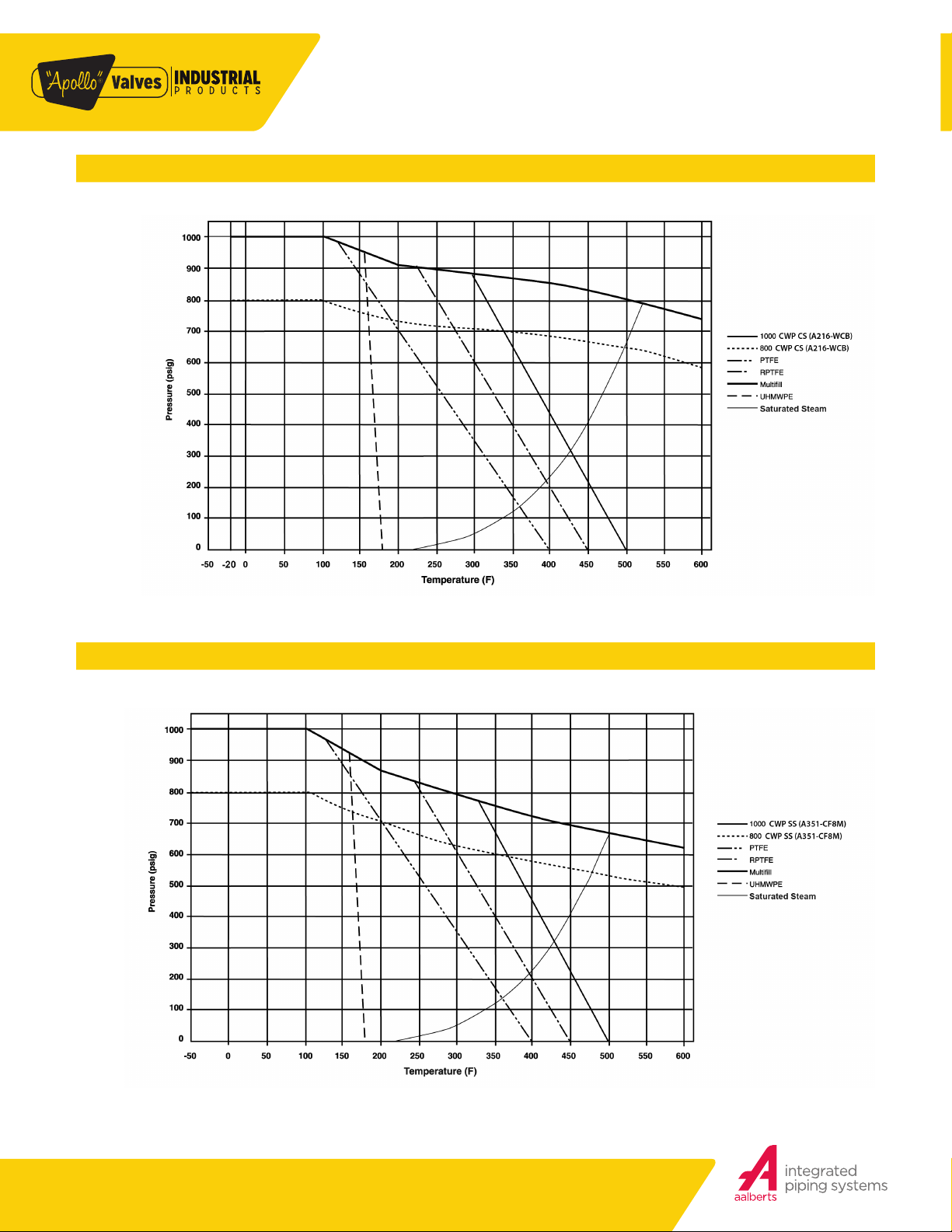
PRESSURE/TEMPERATURE RATINGS
ENGINEERING DATA
1000 CWP (CS) ASTM A216-WCB GRAPH 7
1000 CWP (SS) ASTM A351-CF8M GRAPH 8
Customer Service (704) 841-6000 industrial.apollovalves.comM-12
 Loading...