

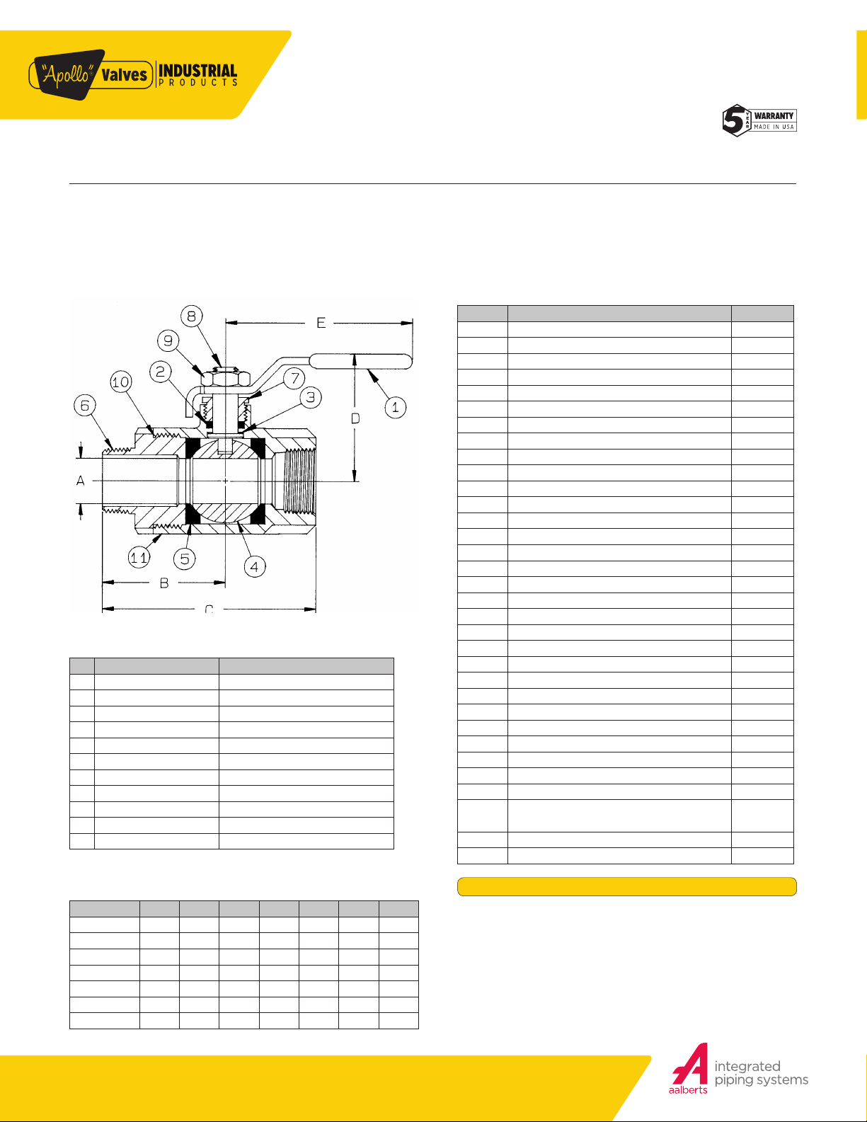
70-800 SERIES
MALE x FEMALE BRONZE BALL VALVE
Male x Female NPT Thread, 600 CWP (psig), Cold Non-Shock. 150 psig Saturated Steam. (See referenced P/T chart)
Vacuum Service to 29 inches Hg.
MSS SP-110 Compliant.
FEATUR E S
• Two-piece body
• Reinforced seats
• Male x female threaded end connections
• Blowout-proof stem design
• Adjustable packing gland
STANDARD MATERIAL LIST
PART MATERIAL
Lever and grip Steel, zinc plated w/vinyl
1
Stem packing MPTFE
2
Stem bearing RPTFE
3
Ball B16 Brass, chrome plated
4
Seat (2) RPTFE
5
Retainer B16 Brass
6
Gland nut B16 Brass
7
Stem B16 Brass
8
Lever nut Steel, zinc plated
9
Body seal (1-1/4” to 1-1/2”) PTFE
10
Body B584-C84400
11
VAR I ATION S AVAILABLE
• 70-840 Series (316 SS Ball & Stem)
OPTIONS AVAILABLE
(MORE INFORMATION IN SECTION J)
• Minimum quantities apply
• To specify an option , replace the “01 ” standard sux with the su x of the option.
• To specify multipl e options, repla ce the “01 ” sux with the des ired su xes in the
numer ical ord er shown b elow. NOTE: Not all suxes can b e combin ed together.
(SUFFIX) OPTION SIZES
-01 Standard Configuration All
-02- Stem Grounded All
-04- 2-1/4” Stem Extension (Carbon Steel, Zinc Plated) All
-05- Plain Ball All
-07- Steel Tee Handle All
-08- 90º Reversed Stem All
-10- SS Lever & Nut All
-11- Therma-Seal™ Insulating Handle All
-14- Side Vented Ball (Uni-Directional) All
-15- Wheel Handle, Steel All
-16- Chain Lever - Vertical 3/4” to 1-1/2”
-21- UHMWPE Trim (Non-PTFE) All
-24- Graphite Packing All
-27- SS Latch- Lock Lever & Nut All
-30- Cam-Lock and Grounded All
-32- SS Tee Handle & Nut All
-35- PTFE Trim All
-39- SS Hi-Rise Locking Wheel Handle, SS Nut All
-40- Cyl-Loc and Grounded All
-41- Automatic Drain (+50°F to 200°F limit. 125 psig max .) All
-45- Less Lever & Nut All
-46- Latch Lock Lever - Lock in Closed Position Only All
-47- SS Oval Latch-Lock Handle & Nut All
-48- SS Oval Handle (No Latch) & Nut All
-49- No Lubrication. Assembled Dry. All
-50- 2-1/4” CS Locking Stem Extension All
-56- Multifill Seats & Packing All
-57- Oxygen Cleaned All
-58- Chain Lever - Horizontal 3/4” to 1-1/2”
-60- Static Grounded Ball & Stem All
-64-
-92- Balancing Stop All
-94 2-1/4” Stem Extension, Balancing Stop All
250# Steam Trim (MPTFE Seats & Packing)
Use with 316 SS Ball & Stem Variation
All
DIMENSIONS
PART NO. SIZE A B C D E WT.
70-801-01 1/4” 0.37 1.40 2.43 1.75 3.87 0.63
70-802-01 3/8” 0.37 1.46 2.50 1.75 3.87 0.60
70-803-01 1/2” 0.50 1.68 2.81 1.81 3.87 0.72
70-804-01 3/4” 0.68 2.00 3.50 2.12 4.87 1.42
70-805-01 1” 0.87 2.31 4.00 2.25 4.87 1.93
70-806-01 1- 1/4 ” 1.00 2.31 4.31 2.62 5.50 3.19
70-807-01 1-1/2” 1.25 3.00 5.18 3.06 8.00 4.60
Customer Service (704) 841-6000 industrial.apollovalves.comA-8
Pressure/Temperature Ratings - Page M-10, Graph No. 4
FLOW DATA
FLOW DATA
The listed Cv “factors” are derived from actual flow testing, at Apollo’s Pageland, South Carolina factory. These tests were completed using standard
“o the shelf” valves with no special preparation and utilizing standard schedule 40 pipe. It should be understood that these factors are for the valve
only and also include the connection configuration. The flow testing is done utilizing water as a fluid media and is a direct statement of the gallons of
water flowed per minute with a 1 psig pressure dierential across the valve/connection unit. Line pressure is not a factor. Because the C
formula can be used to estimate flow of most media for valve sizing.
is a factor, the
v
FLOW OF LIQUID
Q = C
or ∆P =
V
(Q)2 (SpGr)
WHERE:
• Q = Flow in US gpm
• ∆P = Pressure drop (psig)
• SpGr = Specific gravity at flowing temperature
• C
= Valve constant
v
√
(C
∆P
SpGr
2
)
v
FLOW OF GAS
Q = 1360 C
or ∆P =
V
5.4 x 10
(∆P) (P
(SpGr) (T)
√
-7
(SpGr) (T) (Q)
2)
(Cv)2 (P2)
WHERE:
• Q = Flow in SCFH
• ∆P = Pressure drop (psig)
• SpGr = Specific gravity (based on air = 1.0)
• P2 = Outlet pressure–psia (psig + 14.7)
• T = (temp. °F + 460)
• C
= Valve constant
v
CAUTION: The gas equation shown, is valid at very low pressure drop ratios.
The gas equation is NOT valid when the ratio of pressure drop (∆P) to inlet
NOTE: Only use the gas equation shown if (P1-P2)/P1 is less than 0.02.
pressure (P1) exceeds 0.02.
CV FACTORS FOR APOLLO VALVES (CONTINUED ON M-4)
VALVE
70B-140 Series 8.4 7.2 15 30 43 48 84 108 190 370 670 -- -- -- --
70-100/200 Series 8.4 7.2 15 30 43 48 84 108 190 370 670 -- -- -- ---
70-30 0/400 Series -- -- 15 30 43 48 84 108 -- -- -- -- -- -- --
70-600 Series 2.3 4.5 5.4 12 14 21 34 47 -- -- -- -- -- -- --
70-800 Series 8.4 7.2 15 30 43 48 84 -- -- -- -- -- -- -- --
71-AR Series -- -- -- 30 43 48 84 108 190 370 -- -- -- -- --
71-100/200 Series -- -- -- 30 43 48 84 108 190 370 -- -- -- -- --
72-100/900 Series -- -- 26 48 65 125 170 216 -- -- -- -- -- -- --
72-1xx-A/72-9xx-A Series -- -- 26 48 65 125 170 245 -- -- -- -- -- -- --
73A-100 Series 8.4 7.2 15 30 43 48 84 108 -- -- -- -- -- -- --
73-30 0/400 Series -- -- 26 48 65 125 170 216 -- -- -- -- -- -- --
74-100 Series 8.4 7. 2 15 30 43 48 84 108 190 370 670 -- -- -- --
75-10 0 Series 8.4 7. 2 15 30 43 48 84 108 190 370 670 -- -- -- --
76-AR Series 8.4 7.2 15 30 43 48 84 108 190 370 670 -- -- -- --
76F-100 Series 8.1 15 15 51 68 125 177 389 -- -- -- -- -- -- --
76FJ-100 Series 8.1 15 15 51 68 125 177 389 -- -- -- -- -- -- --
76FK-100 Series 8.1 15 15 51 68 125 177 389 -- -- -- -- -- -- --
76-100 Series 8.4 7.2 15 30 43 48 84 108 190 370 -- -- -- -- --
76-300/400 Series -- -- 26 48 65 125 170 216 -- -- -- -- -- -- --
76-600 Series 2.3 4.5 5.4 12 14 21 34 47 -- -- -- -- -- -- --
76J-100 Series 8.4 7.2 15 30 43 48 84 108 190 370 -- -- -- -- --
76J-AR Series 8.4 7.2 15 30 43 48 84 108 190 370 670 -- -- -- --
76K-100 Series 8.4 7.2 15 30 43 48 84 108 190 370 -- -- -- -- --
76K-AR Series 8.4 7.2 15 30 43 48 84 108 190 370 670 -- --
7K-100 Series -- -- 15 51 68 125 177 389 503 -- -- -- -- -- --
77-AR Series 8.1 15 15 51 68 -- 177 389 -- -- -- -- -- -- --
1/4 3/8 1/2 3/4 1 1.25 1.5 2 2.5 3 4 6 8 10 12
SIZE (IN.)
-- --
REV. 21APR17
2
Customer Service (704) 841-6000 industrial.apollovalves.com M-3

FLOW DATA
FOR APOLLO BALL VALVES
CV FACTORS FOR APOLLO VALVES (CONTINUED FROM M-3)
VALVE
77C-10 0/200 Series 4.5 7. 2 16 36 68 125 177 389 503 -- -- -- -- -- --
77D-140 Series 4.5 7. 2 16 36 68 125 177 389 -- -- -- -- -- -- --
77D- 640 Series -- -- -- 11 24 35 -- -- -- -- -- -- -- -- --
77G-UL Series 4.5 7.2 16 36 68 125 177 389 503 -- -- -- -- -- --
77W Series -- -- 16 36 68 125 177 389 -- -- -- -- -- -- --
77-100/200 Series 8.1 15 15 51 68 125 177 389 503 -- -- -- -- -- --
79 Series 8.5 8.5 9.8 32 44 66 148 218 440 390 -- -- -- -- --
80 Series 8.4 7. 2 15 30 43 48 84 108 190 370 -- -- -- -- --
82-100/200 Series 8.1 14 26 51 68 120 170 376 510 996 1893 -- -- -- --
83A/83B Series 8.1 14 26 51 68 120 170 376 -- -- -- -- -- -- --
83R-100/200 Series -- -- -- -- -- -- 170 376 -- 996 1893 -- -- -- --
86A/86B Series 8.1 14 26 51 68 120 170 376 -- -- -- -- -- -- --
86R-100/200 Series -- -- -- -- -- -- 170 376 -- 996 1893 -- -- -- --
87A-100 Series -- -- -- -- -- -- 86 104 234 375 673 1099 1902 3890 --
87A-200 Series -- -- 15 19 75 -- 195 410 545 1021 2016 4837 9250 15170 22390
87A-700 Series -- -- -- -- -- -- 86 104 234 375 673 1099 1902 3890 --
87A-900 Series -- -- 15 19 75 -- 195 410 545 1021 2016 4837 9250 15170 22390
87A-F00 Series -- -- -- -- 75 -- 195 410 545 1021 2016 4837 -- -- --
87B-10 0 Series -- -- -- -- -- -- -- -- -- 375 673 1099 1902 3890 --
87J-100 Series -- -- -- -- -- -- 86 104 234 375 673 1099 1902 3890 --
87J-200 Series -- -- 15 19 75 -- 195 410 545 1021 2016 4837 9250 15 170 22390
87J-700 Series -- -- -- -- -- -- 86 104 234 375 673 1099 1902 3890 --
87J-900 Series -- -- 15 19 75 -- 195 410 545 1021 2016 4837 9250 15170 22390
87K-100 Series -- -- -- -- -- -- 86 104 234 375 673 1099 1902 3890
87K-200 Series -- -- 15 19 75 -- 195 410 545 1021 2016 4837 9250 15170 22390
87K-700 Series -- -- -- -- -- -- 86 104 234 375 673 1099 1902 3890 --
87K-900 Series -- -- 15 19 75 -- 195 410 545 1021 2016 4837 9250 15170 22390
88A-100 Series -- -- -- -- -- -- 86 104 234 375 673 1099 1902 3890 --
88A-200 Series -- -- 15 19 75 -- 195 410 545 1021 2016 4837 9250 15170 22390
88A-700 Series -- -- -- -- -- -- 86 104 234 375 673 1099 1902 3890 --
88A-900 Series -- -- 15 19 75 -- 195 410 545 1021 2016 4837 9250 15170 22390
88A-F00 Series -- -- -- -- 75 -- 195 410 545 1021 2016 4837 -- -- --
88B-100 Series -- -- -- -- -- -- -- -- -- 375 673 1099 1902 3890 --
89-100 Series 8.4 7.2 15 30 43 48 84 108 190 370 -- -- -- -- --
9A-100 Series 8.3 6.7 5.7 10 16 25 40 62 -- -- -- -- -- -- --
90-100 Series 8.3 6.7 5.7 10 16 25 40 62 -- -- -- -- -- -- --
92-100 Series 8.3 6.7 5.7 10 16 25 40 62 -- -- -- -- -- -- --
93-100 Series 8.3 6.7 5.7 10 16 25 40 62 -- -- -- -- -- -- --
94A-100/200 Series 6 7 19 34 50 104 268 309 629 1018 1622 -- -- -- --
96-100 Series 8.3 6.7 5.7 10 16 25 40 62 -- -- -- -- -- -- --
399-100 Series 8.4 7. 2 15 30 43 48 84 108 190 370 -- -- -- -- --
489-100 Series 8.4 7. 2 15 30 43 48 84 108 190 370 -- -- -- -- --
1/4 3/8 1/2 3/4 1 1.25 1.5 2 2.5 3 4 6 8 10 12
SIZE (IN.)
--
Customer Service (704) 841-6000 industrial.apollovalves.comM-4
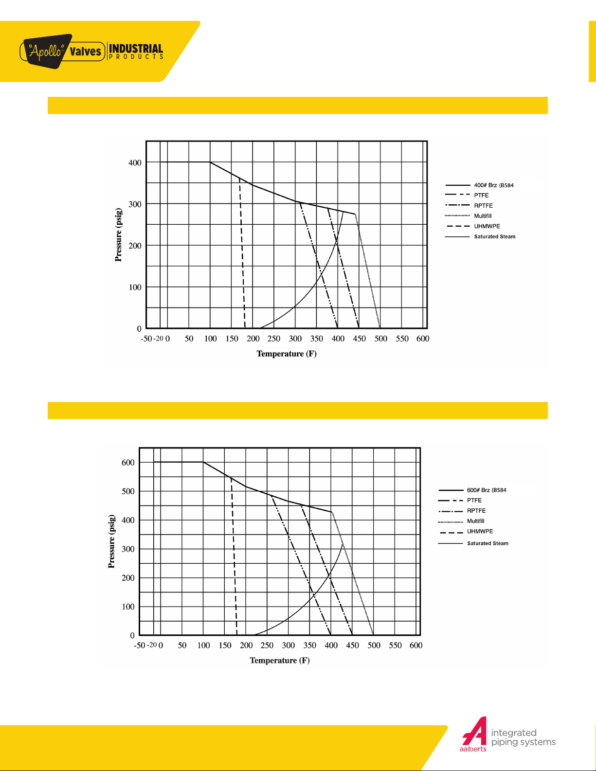
PRESSURE/TEMPERATURE RATINGS
ENGINEERING DATA
400 CWP BRONZE ASTM B584 GRAPH 3
600 CWP BRONZE ASTM B584 GRAPH 4
Customer Service (704) 841-6000 industrial.apollovalves.comM-10
 Loading...