

Apollo XPA-CB-12034-APO, XPA-WB-10022-APO, XPA-CB-13032-APO, XPA-CB-11170-APO, XPA-OH-13023-APO Installation Manual
...Page 1

39214-394/Issue 3
Battery Type
6 x AA, 1.5V Alkaline Duracell Procell (MN1500, LR6)
When replacing batteries, allow the device to power down for a per iod of t wo minutes
before installing replacements.
Note: When replacement batteries are required all batter ies must be replaced together.
Technical Data
Operating voltage 2.8-5VDC
Operating temperature –10°C to +50°C
XPander Smoke and Heat Detectors
Installation Guide
General
Do not install any XPander equipment until a full site survey has been completed using the
XPander site survey tool. A maximum of 5 interfaces are permitted for each site. For sites
that require more than 5 interfaces please contact Apollo. All installation engineers must
have had certied XPander training.
The XPander smoke and heat detector variants are available under the following part
numbers:
Complete Units
Part Number Description
XPA-CB-12034-APO XPande r Optical detecto r with base
XPA-CB-13032-APO XPande r Multisen sor detector with base
XPA - CB -11170 - AP O XPande r Heat A1R detector with base
XPA - CB -11171- AP O XPande r Heat C S detecto r with base
© Apol lo Fi re Detectors Limite d 2006-2 010
Apollo Fire Detectors Limited, 36 Brookside Road, Havant, Hampshire, PO9 1JR, UK
Tel: +44 (0) 23 9249 2412 Fax: +44 (0) 23 9249 2754
Email: techsales@apollo-re.co.uk Website: www.apollo-re.co.uk
Spares
Part Number Description
XPA-WB-10022-APO XPande r Mounting base only
XPA-OP-12034-APO XPander O ptical head only
XPA-OH-13023-APO XPander Multisensor head only
XPA - HT -1117 0 -A P O XPande r Heat A1R head only
XPA - HT -11171- AP O XPande r Heat C S head o nly
The installation must conform to BS5839-1 (or applicable local codes). All detectors are suit-
able for indoor use only.
1
Page 2
Installation
© Apollo Fire Detectors Limited 2007 TP
1
2
4
8
16
32
64
1
1
1
2
4
8
16
32
64
10
10
1
2
4
8
16
32
64
9
9
1
2
4
8
16
32
64
8
8
1
2
4
8
16
32
64
7
7
1
2
4
8
16
32
64
6
6
1
2
4
8
16
32
64
5
5
1
2
4
8
16
32
64
4
4
1
2
4
8
16
32
64
3
3
1
2
4
8
16
32
64
2
2
1
2
4
8
16
32
64
11
11
1
2
4
8
16
32
64
20
20
1
2
4
8
16
32
64
19
19
1
2
4
8
16
32
64
18
18
1
2
4
8
16
32
64
17
17
1
2
4
8
16
32
64
16
16
1
2
4
8
16
32
64
15
15
1
2
4
8
16
32
64
14
14
1
2
4
8
16
32
64
13
13
1
2
4
8
16
32
64
12
12
1
2
4
8
16
32
64
21
21
1
2
4
8
16
32
64
30
30
1
2
4
8
16
32
64
29
29
1
2
4
8
16
32
64
28
28
1
2
4
8
16
32
64
27
27
1
2
4
8
16
32
64
26
26
1
2
4
8
16
32
64
25
25
1
2
4
8
16
32
64
24
24
1
2
4
8
16
32
64
23
23
1
2
4
8
16
32
64
22
22
1
2
4
8
16
32
64
31
31
1
2
4
8
16
32
64
40
40
1
2
4
8
16
32
64
39
39
1
2
4
8
16
32
64
38
38
1
2
4
8
16
32
64
37
37
1
2
4
8
16
32
64
36
36
1
2
4
8
16
32
64
35
35
1
2
4
8
16
32
64
34
34
1
2
4
8
16
32
64
33
33
1
2
4
8
16
32
64
32
32
1
2
4
8
16
32
64
41
41
1
2
4
8
16
32
64
50
50
1
2
4
8
16
32
64
49
49
1
2
4
8
16
32
64
48
48
1
2
4
8
16
32
64
47
47
1
2
4
8
16
32
64
46
46
1
2
4
8
16
32
64
45
45
1
2
4
8
16
32
64
44
44
1
2
4
8
16
32
64
43
43
1
2
4
8
16
32
64
42
42
1
2
4
8
16
32
64
51
51
1
2
4
8
16
32
64
60
60
1
2
4
8
16
32
64
59
59
1
2
4
8
16
32
64
58
58
1
2
4
8
16
32
64
57
57
1
2
4
8
16
32
64
56
56
1
2
4
8
16
32
64
55
55
1
2
4
8
16
32
64
54
54
1
2
4
8
16
32
64
53
53
1
2
4
8
16
32
64
52
52
1
2
4
8
16
32
64
63
63
1
2
4
8
16
32
64
62
62
1
2
4
8
16
32
64
61
61
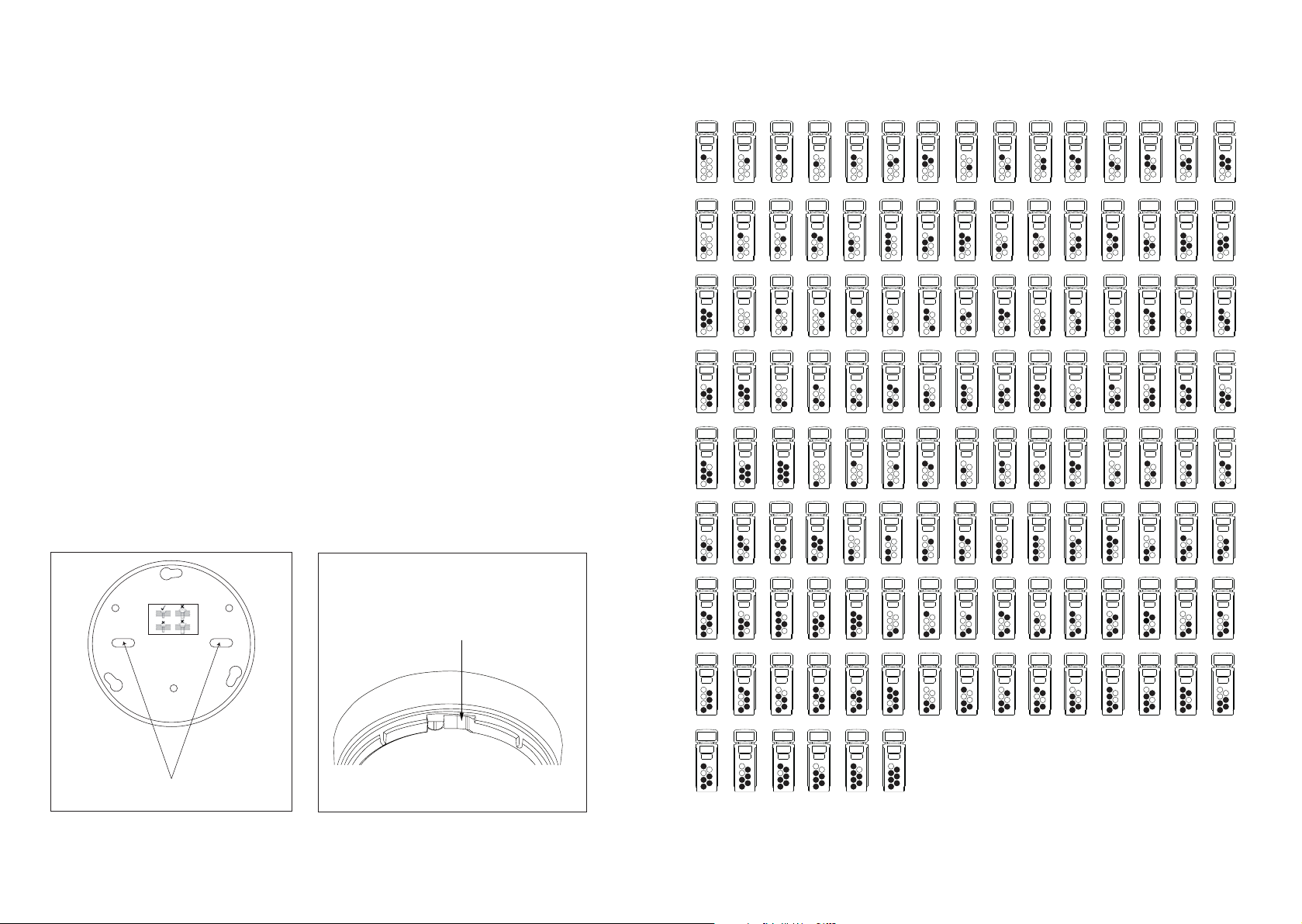
XPERT card addressing forXP95 and Discovery
Select the desired address and remove the pips indicated in black. Remove pips with a small screwdriver.
1
2
4
8
16
32
64
124
124
1
2
4
8
16
32
64
126
126
1
2
4
8
16
32
64
125
125
1
2
4
8
16
32
64
80
80
1
2
4
8
16
32
64
79
79
1
2
4
8
16
32
64
78
78
1
2
4
8
16
32
64
77
77
1
2
4
8
16
32
64
76
76
1
2
4
8
16
32
64
70
70
1
2
4
8
16
32
64
69
69
1
2
4
8
16
32
64
68
68
1
2
4
8
16
32
64
67
67
1
2
4
8
16
32
64
66
66
1
2
4
8
16
32
64
65
65
1
2
4
8
16
32
64
64
64
1
2
4
8
16
32
64
71
71
1
2
4
8
16
32
64
75
75
1
2
4
8
16
32
64
74
74
1
2
4
8
16
32
64
73
73
1
2
4
8
16
32
64
72
72
1
2
4
8
16
32
64
81
81
1
2
4
8
16
32
64
90
90
1
2
4
8
16
32
64
89
89
1
2
4
8
16
32
64
88
88
1
2
4
8
16
32
64
87
87
1
2
4
8
16
32
64
86
86
1
2
4
8
16
32
64
85
85
1
2
4
8
16
32
64
84
84
1
2
4
8
16
32
64
83
83
1
2
4
8
16
32
64
82
82
1
2
4
8
16
32
64
91
91
1
2
4
8
16
32
64
100
100
1
2
4
8
16
32
64
99
99
1
2
4
8
16
32
64
98
98
1
2
4
8
16
32
64
97
97
1
2
4
8
16
32
64
96
96
1
2
4
8
16
32
64
95
95
1
2
4
8
16
32
64
94
94
1
2
4
8
16
32
64
93
93
1
2
4
8
16
32
64
92
92
1
2
4
8
16
32
64
101
101
1
2
4
8
16
32
64
110
110
1
2
4
8
16
32
64
109
109
1
2
4
8
16
32
64
108
108
1
2
4
8
16
32
64
107
107
1
2
4
8
16
32
64
106
106
1
2
4
8
16
32
64
105
105
1
2
4
8
16
32
64
104
104
1
2
4
8
16
32
64
103
103
1
2
4
8
16
32
64
102
102
1
2
4
8
16
32
64
111
111
1
2
4
8
16
32
64
120
120
1
2
4
8
16
32
64
119
119
1
2
4
8
16
32
64
118
118
1
2
4
8
16
32
64
117
117
1
2
4
8
16
32
64
116
116
1
2
4
8
16
32
64
115
115
1
2
4
8
16
32
64
114
114
1
2
4
8
16
32
64
113
113
1
2
4
8
16
32
64
112
112
1
2
4
8
16
32
64
123
123
1
2
4
8
16
32
64
122
122
1
2
4
8
16
32
64
121
121
Snip along marked lines and remove this
part to lock the detector to the base.
Apollo Fire Detectors Limited 2008/TP
All detectors must be sited in accordance with the original approved design and site
survey details. Where practical the detector’s LED should face towards the room’s
entrance.
1. Twist the ceiling mounting plate anti-clock wise to remove it from the mounting base.
2. The ceiling mounting plate must be tted using both mounting holes and suitable
xings or fasteners. (Fig 1)
Note: Any screw heads must be ush or semi ush with the internal surface of the ceiling
mount otherwise the battery PCB may be damaged.
3. Attach the mounting base to the ceiling mounting plate ensuring the tamper switch
spring assembly makes contact. Locate the three lugs and twist clockwise.
4. Fit the detector to the mounting base.
5. Fit the power jumper shorting link and commission the unit according to the XPander
Locking Mechanism
The detectors can be locked into the base by removing a tab as shown in Fig.2.
To unlock the detector, insert a 1.5mm hex driver or similar diameter tool into the small hole
opposite the XPERT card and twist the detector anti-clock wise.
The XPander base module can be locked to the mounting plate by means of a grub screw.
Access to which is through the base module cover label opposite the XPERT card
The address of the unit is set using the XPERT card, see table overleaf. Commission the
detector according to the XPander commissioning guide PP2286.
XPERT card insertion and removal
commissioning guide PP2286.
Removal requires access to the inner section of the base. Detach the detector from its
base. Insert a at-blade screwdriver just inside the rim of the base above the XPERT card
and disengage the card retaining clip whilst pulling the XPERT card out.
XPERT Card Addressing
The XPander XPERT card is specically designed for XPander products and has proled
address pips for ease of installation. The use of standard XPERT cards is not recommended.
Select the desired address and remove the pips indicated in black. Remove pips with a
small screwdriver.
Fig 1 Mounting details
Fig 2. Locking Mechanism
32
 Loading...