

Page 1

XP95 ENGINEERING PRODUCT GUIDE
Ionisation Smoke Detector
Optical Smoke Detector
Heat Detector
Multisensor Detector
Manual Call Point
Isolating Base
Sounders & Beacons
Page 2

The XP95 range of intelligent fire detectors is
advanced in design, improved in performance and
has unique features that benefit the installer and
the end user. The range includes ionisation and
optical smoke detectors, heat detectors as well as
a multisensor. All have an unobtrusive profile, a
zero insertion force base, user friendly addressing
and extended data and alarm features. A manual
call point, an isolating base, sounders, beacons
and other compatible products are also available.
These detectors have been carefully researched
and developed by the Apollo design team and the
range has undergone rigorous testing to ensure
that it meets not only European and other
standards but also the demands of today’s high
technology environments.
This Product Guide aims to provide engineers with
full information on XP95, in order to be able to
design optimum solutions to fire protection
problems.
Key features
Analogue Value Report
•
Digital data transmission
•
Input Bits Reporting
•
Interrupt Warning
•
Apollo Fire Detectors Limited, part of the Halma
plc group of companies, operates from one site at
Havant, near Portsmouth, England. All departments
– Research and Development, Sales and Marketing,
Manufacturing and Finance – are located there.
Apollo applies the most modern production
techniques and has invested in sophisticated
manufacturing equipment to ensure consistent
high quality of product and fast response to
customer requirements. Through planned
expansion Apollo has reached a leading position
in the market for professional fire detectors and
exports over half of its production to countries
around the world.
Automatic Type Identification
•
Address Confirmation
•
XP95 Device Flag
•
Information in this guide is given in good faith, but Apollo Fire
Detectors Limited cannot be held responsible for any omissions
or errors . The company res erves the right to change
specifications of products at any time without prior notice.
Page 3

XP95 TABLE OF CONTENTS
Application of XP95 Detectors 4
Addressing and Communications 4
Features of the XP95 Range 5
Ionisation Smoke Detector
Operating principles 6
Electrical description 7
Environmental characteristics 7
Safety note 7
Technical data 7
Optical Smoke Detector
Operating principles 9
Electrical description 9
Environmental characteristics 9
Technical data 10
Heat Detector
Operating principles 11
Electrical description 11
Environmental characteristics 11
Technical data 12
Multisensor Detector
Operating principles 13
Technical data 14
Manual Call Point
Operating principles 15
Technical data 16
XP95 Mounting Base 17
XP95 20D Isolating Base
Operating principles 18
Electrical description 18
Technical data 18
XP95 Isolator 19
XP95 Loop-Powered Beam Detector 19
Intelligent Reflective Beam Detector 19
MiniDisc Remote Indicator 19
Loop-powered Sounders, Beacon & Sounder Beacons 19
XP95 Flame Detector 20
page
3
Approvals and Regulatory Compliance 21
EMC 21
Maintenance of Detectors 22
Page 4

APPLICATION OF XP95 DETECTORS
ADDRESSING AND COMMUNICATIONS
page
4
The choice of detector from the XP95 range follows the
well established principles of system design. That is, the
optimum detector type will depend on the type of fire risk
and fire load, and the type of environment in which the
detector is sited.
For general use, smoke detectors are recommended since
these give the highest level of protection. Smoke detectors
from the XP95 range may be ionisation, optical or
multisensor types. It is generally accepted that ionisation
types have a high sensitivity to flaming fires whereas
optical detectors have high sensitivity to smouldering fires.
As a result of this, ionisation types are widely used for
property protection, and optical types for life protection.
These general principles still apply to XP95 detectors
although the availability of a multisensor in the range
offers more choice to the system designer.
The multisensor is basically an optical smoke detector and
will therefore respond well to the smoke from smouldering
fires. The detector also senses air temperature. This
temperature sensitivity allows the multisensor to give a
response to fast burning (flaming) fires, which is similar to
that of an ionisation detector. The multisensor can
therefore be used as an alternative to an ionisation detector
Where the environment is smoky or dirty under normal
conditions, a heat detector may be more appropriate. It
must be recognised, however, that any heat detector will
respond only when the fire is well established and
generating a high heat output.
Unless otherwise specified, devices described in this guide
are suitable for indoor use only.
Each XP95 device responds to interrogation and command
from central control equipment. It communicates to the
panel information on status, command bits, type, location,
and other information that allows an alarm to be raised
even when the device is not itself being interrogated.
Message error checking is also provided. The devices are
compatible with Series 90, Discovery®and XPlorer systems
and control equipment to aid maintenance, extension and
upgrade of existing systems.
A unique, patented XPERT card provides simple, user
friendly and accurate identification of detector location
whereby a coded card, inserted in the base, is read by
any detector once it is plugged in. All the electronic
components are in the detector but the location information
is held in the base. The address card simplifies and speeds
up installation and commissioning. Addressing errors
during maintenance and service are eliminated.
The XP95 manual call point continues to use DIL switch
addressing, but its interrupt feature also provides automatic
reporting of its location in the interrupt mode.
The XP95 detectors provide an alarm facility that automatically
puts an alarm flag on the data stream and reports its address
when the pre-set EN54 thresholds are exceeded. The
devices provide great flexibility in system design with the
control equipment determining the characteristics of the
system. A large and growing range of compatible control
equipment is available from many sources - details are
included in Apollo publication PP1010, which is available
on request.
Page 5

Ionisation Optical Multisensor Heat
Overheating/thermal combustion Poor Very Good Very Good Very Poor
Smouldering/glowing combustion Moderate/Good Good Good Very Poor
Flaming combustion Very Good Good Good Poor
Flaming with high heat output Very Good Good Very Good Moderate/Good
Flaming - clean burning Poor Very Poor Moderate/Good Moderate/Good
Table1 Response characteristics of smoke and heat detectors.
PROTOCOL FEATURES
Control Unit Interrogation and Command:
3 bits of command instruction and the 7- bit address are
issued by the control equipment following an initiating pulse.
Interrupt Warning:
Notification that an XP95 manual call point or XP95 Mini
Switch Monitor (interrupt) has been operated.
Analogue Value Report:
Status continually reported.
Input Bits Reporting:
Field devices advise control equipment of actions they have
taken. For smoke and temperature detectors, these confirm
compliance with the output command bits. Bit information
depends on device type.
Automatic Type Identification:
The device being interrogated replies with a 5 bit type
code, allowing up to 32 device types.
Address Confirmation:
The 7- bit address (up to 126 devices per loop) of the
detector responding is confirmed back to the control unit.
XP95 Device Flag:
Tells the control equipment that more information is available.
Alarm Flag:
For accelerated alarm reporting.
Parity Error Check:
For received message accuracy.
Interrupt or Alarm Address:
Provides fast location of a device in alarm state.
ENGINEERING FEATURES
High Level Integration:
ASICs technology for lower component count.
Zero Insertion Force Base:
For easier installation and maintenance.
Ease of Maintenance:
Snap lock chambers for easy cleaning.
Surface Mounted Components:
For long life and high reliability
Latest Data Reported:
As well as free running data update, device will update
data when the preceding device is being interrogated.
XPERT Card Addressing:
For fast reliable installation and service.
Unobtrusive Design:
For elegant designs in modern buildings.
page
5
Page 6

XP95 IONISATION SMOKE DETECTOR
Fig.1 Sectional view - XP95 Ionisation Smoke Detector
page
6
XP95 Ionisation Smoke Detector Part Number 55000-500
outer smoke chamber (Fig 1).
OPERATING
PRINCIPLES
The XP95 ionisation smoke
detector has a moulded
self-extinguishing white
polycarbonate case with
wind resistant smoke inlets.
Stainless steel wiper contacts
connect the detector to the
terminals in the mounting
base. Inside the detector case
is a printed circuit board that
has the ionisation chamber
mounted on one side and
the address capture, signal
processingandcommunications
electronics on the other.
The ionisation chamber
system is an inner reference
chamber contained inside an
The outer smoke chamber
has smoke inlet apertures
that are fitted with an insect
resistant mesh.
The radioactive source
holder and the outer smoke
chamber are the positive
and negative electrodes
respectively. An Americium
241 radioactive source
mounted within the inner
reference chamber irradiates
the air in both chambers to
produce positive and
negative ions. On applying a
voltage across these
electrodes an electric field is
formed as shown in Fig 2.
The ions are attracted to the
electrode of the opposite
sign, some ions collide and
recombine, but the net result
is that a small electric current
flows between the electrodes.
At the junction between the
reference and smoke chambers
is the sensing electrode that is
used to convert variations in
the chamber currents into a
voltage.
When smoke particles enter
the ionisation chamber, ions
become attached to them
with the result that the current
flowing through the ionisation
chamber decreases. This
effect is greater in the smoke
chamber than in the reference
chamber and the imbalance
causes the sensing electrode
to go more positive.
The voltage on the sensing
electrode is monitored by
the sensor electronics and
is processed to produce a
signal that is translated by
the A/D converter in the
communications ASIC ready
for transmission when the
device is interrogated.
Fig.2 Diagramshowing lines of equipotential fortheXP95 Ionisation Smoke Monitor
Page 7
ELECTRICAL
DESCRIPTION
he detector is designed to
T
be connected to a two wire
loop circuit carrying both
data and a 17V to 28V dc
supply. The detector is
connected to the incoming
and outgoing supply via
terminals L1 and L2 in the
mounting base. A remote
LED indicator requiring not
more than 4mA at 5V may
be connected between +R
and -R terminals. An earth
connection terminal is also
provided, although this is
not required for the
functioning of the detector.
When the device is energised
the ASICs regulate the flow
of power and control the data
processing. The ionisation
chambers are energised and
the ultra low leakage sensor
ASIC provides a conditioned
analogue signal to the
analogue to digital (A/D)
converter within the
communications and
processing ASIC. When
smoke enters the ionisation
chambers through the integral
gauze, the voltage at the
sensing electrode increases to
produce an analogue signal.
An A/D conversion of the
signal from the ionisation
chambers is carried out once
per second or when either
the detector or preceding
address is being interrogated.
Whenever the device is
interrogated this data is sent
to the control equipment.
EN54 threshold alarm levels
are calibrated within the
processing ASIC. If the
device is not addressed
within 1 second of its last
polling and the analogue
value is greater than 55 the
alarm flag is initiated and
the device address is added
to the data stream every 32
olling cycles from its last
p
polling for the duration of
the alarm level condition,
except when the alarming
device is being interrogated.
This can provide a location
identified alarm from any
device on the loop in
approximately two seconds.
The detector is calibrated to
give an analogue value of
25±7 counts in clean air. This
value increases with smoke
density. A count of 55
corresponds to the EN54 alarm
sensitivity level. See Fig 3.
Counts of 8 or less indicate
fault conditions. Count levels
between 45 counts and 55
counts can be used to provide
an early warning of fire.
ENVIRONMENTAL
CHARACTERISTICS
XP95 ionisation smoke
detectors are designed to
operate in a wide variety of
environments (See Figs 4 to
6). There are only small
effects from temperature,
humidity, atmospheric
pressure and wind. Detectors
are well protected against
electromagnetic interference
over a wide frequency range.
The XP95 ionisation detector,
like all ionisation detectors,
has some sensitivity to air
movement (wind). The
extent to which the analogue
value will change depends
on the wind speed and on
the orientation of the
detector relative to the wind
direction. Relatively small
changes in wind direction
can cause significant changes
in analogue value.
Fig.3 Typical response characteristics - XP95 Ionisation Detector
Fig.4 Typical temperature response - XP95 Ionisation Detector
page
7
Fig.5 Typical pressure response - XP95 Ionisation Detector
Fig.6 Typical wind speed response - XP95 Ionisation Smoke Detector
Page 8

TECHNICAL DATA
XP95 Ionisation
Detector Part No 55000-500/
520/560
ase Part No 45681-210
B
Specifications are typical
and given at 23°C and 50%
relative humidity unless
otherwise stated.
Detector Type:
Point type smoke detector for
fire detection and fire alarm
systems for buildings
Detection Principle:
Ionisation Chamber
Chamber Configuration:
Twin compensating
chambers using one single
sided ionising radiation
source
Radioactive Isotope:
Americium 241
Activity:
33.3kBq, 0.9µCi
Sampling Frequency:
Continuous
Sensitivity:
Nominal threshold y value of
0.7 to EN54–7:2000
Supply Wiring:
Two wire supply, polarity
nsensitive
i
Terminal Functions:
L1&L2 supply in and out
+R remote indicator
-R remote indicator
Supply Voltage:
17 to 28 Volts dc
Modulation Voltage at
Detector:
5 to 9 Volts peak to peak
Quiescent Current:
280µA average, 500µA peak
Power-up Surge Current:
1mA
Duration of Power-up Surge
Current:
0.3 seconds
Maximum Power-up Time:
4 seconds for communications
(measured from application of
power and protocol)
connections (polarity
insensitive)
positive connection
(internal 2.2kΩ
resistance to supply
ve)
+
negative connection
(internal 2.2kΩ
resistance to supply
- ve)
10 seconds to exceed 10
counts 15 seconds for stable
clean air value
Clean Air Analogue Value:
25±7 counts
larm Level 55 Counts:
A
EN54 y value of 0.7
Alarm Indicator:
Red light emitting diode (LED)
Alarm LED Current:
2mA
Remote LED Current:
4mA at 5V (measured across
remote load)
Type Code:
(210 43) 011 00
Storage Temperature:
-30°C to +80°C
Operating Temperature:
-20°C to +70°C
Guaranteed Temperature
Range:
(No condensation or icing)
-20°C to +60°C
Humidity:
(No condensation or icing)
0% to 95% relative humidity
Wind Speed:
10m/s maximum
Atmospheric Pressure:
Automatic compensation by
dual chambers to maintain
sensitivity up to a height of
2000m above sea level
Vibration, Impact & Shock:
To EN54–7:2000
Electro-magnetic
Compatibility:
See page 21 for full details
IP Rating:
23D
pprovals & Regulatory
A
Compliance:
See page 21 for full details
Dimensions:(diameter x height)
etector: 100mm x 42mm
D
Detector in Base:
100mm x 50mm
Weights:
Detector: 105g
Detector in Base: 161g
Materials:
Detector Housing: White
polycarbonate V-0 rated to
UL 94
Terminals: Nickel plated
stainless steel
0832
page
8
technical data
For wind speeds up to 1m/s
(200ft/min) the change in
analogue value will not
exceed 5 counts.
Continuous operation in
wind speeds greater than
2m/s (400ft/min) is not
recommended. However,
wind speeds up to 10m/s
(2000ft/min) can be tolerated
for short periods and will
not under any conditions
increase the probability of
false alarms.
SAFETY NOTE
In the United Kingdom,
ionisation smoke detectors are
subject to the requirements of
the Radioactive Substances
Act 1993 and to the Ionising
Radiations Regulations 1999
made under the provisions
of the Health and Safety at
Work Act 1974.
The detectors, independently
tested by the National
Radiological Protection
Board (NRPB), conform to all
the requirements specified
in the ‘Recommendations for
ionisation smoke detectors in
implementation of radiation
standards’ published by the
Nuclear Energy Agency of the
Organisation for Economic
Co-operation and
Development (OECD) 1977.
There is no limit to the number
of ionisation smoke detectors
which may be installed in
any fire protection system
within the UK. See
Certificate of Approval No.
TA1 of 1999 issues by the
HSE for further details.
Storage regulations depend
on local standards and the
legislation, but, in the UK, the
number of ionisation smoke
detectors in any building or
premises shall be less than
500. See Certificate of
Approval No. TA3 of 1999
issued by the HSE for further
details.
At the end of their
recommended working life
of ten years, ionisation
smoke detectors should be
returned to Apollo for safe
disposal or disposed of in an
otherwise locally approved
and environmentally safe
manner. Please see "A Guide
to the Care, Maintenance
and Servicing of Apollo
Products", PP2055.
Guidance on storage can be
given by Apollo Fire
Detectors and full details
can be requested from:
Radioactive Substances
Regulation Function
Environment Agency
Rio House, Waterside Drive
Aztec West, Almondsbury,
Bristol, BS32 4UD
Outside the UK, please contact
the relevant national agency.
Page 9

XP95 OPTICAL SMOKE DETECTOR
XP95 Optical Smoke Detector Part Number 55000-600
In clear air the photo-diode
receives no light directly
OPERATING
PRINCIPLES
The XP95 optical detector
uses the same outer case as
the ionisation smoke detector
and is distinguished by the
indicator LED which is clear
in standby and red in alarm.
Within the case is a printed
circuit board which on one
side has the light proof
labyrinth chamber with
integral gauze surrounding
the optical measuring system
and on the other the address
capture, signal processing and
communications electronics.
An infrared light emitting
diode within its collimator is
arranged at an obtuse angle
to the photo-diode. The
photo-diode has an integral
daylight-blocking filter.
The IR LED emits a burst of
collimated light every second.
from the IR LED because of
the angular arrangement
and the dual mask. When
smoke enters the chamber
it scatters photons from the
emitter IR LED onto the
photo-diode in an amount
related to the smoke
characteristics and density.
The photo-diode signal is
processed by the optical
ASIC and passed to the A/D
converter on the
communications ASIC ready
for transmission when the
device is interrogated.
ELECTRICAL
DESCRIPTION
The detector is designed to
be connected to a two wire
loop circuit carrying both
data and a 17V to 28V dc
supply. The detector is
connected to the incoming
and outgoing supply via
erminals L1 and L2 in the
t
mounting base. A remote
LED indicator requiring not
more than 4mA at 5V may
be connected between the
+R and -R terminals. An
earth connection terminal is
also provided.
When the device is energised
the ASICs regulate the flow
of power and control the
data processing. The optical
ASIC is controlled by the
communications ASIC and
pulses the IR LED. The signal
from the photo-diode is
processed by the optical
ASIC and transferred to
the A/D converter in the
communications ASIC
where it is then stored.
When smoke enters the
chamber the photo-diode
signal increases. The
information to the A/D
converter is updated once
per second or when either
the monitor or the preceding
address is interrogated.
Whenever the device is
interrogated this data is sent
to the control equipment.
EN54 threshold alarm levels
are calibrated within the
processing ASIC. If the
Fig.7 Top section - XP95 Optical Smoke Detector
evice is not addressed
d
within 1 second of its last
polling and the analogue
value is greater than the
EN54 alarm level the alarm
lag is initiated and the
f
device address is added to
the data stream every 32
polling cycles from its last
polling for the duration of
the alarm level condition,
except when the alarming
device is being interrogated.
This can provide a location
identified alarm from any
device on the loop in
approximately 2 seconds.
The detector is calibrated to
give an analogue value of
25±7 counts in clean air.
This value increases with
smoke density. A count of 55
corresponds to the EN54 alarm
sensitivity level. See Fig.9.
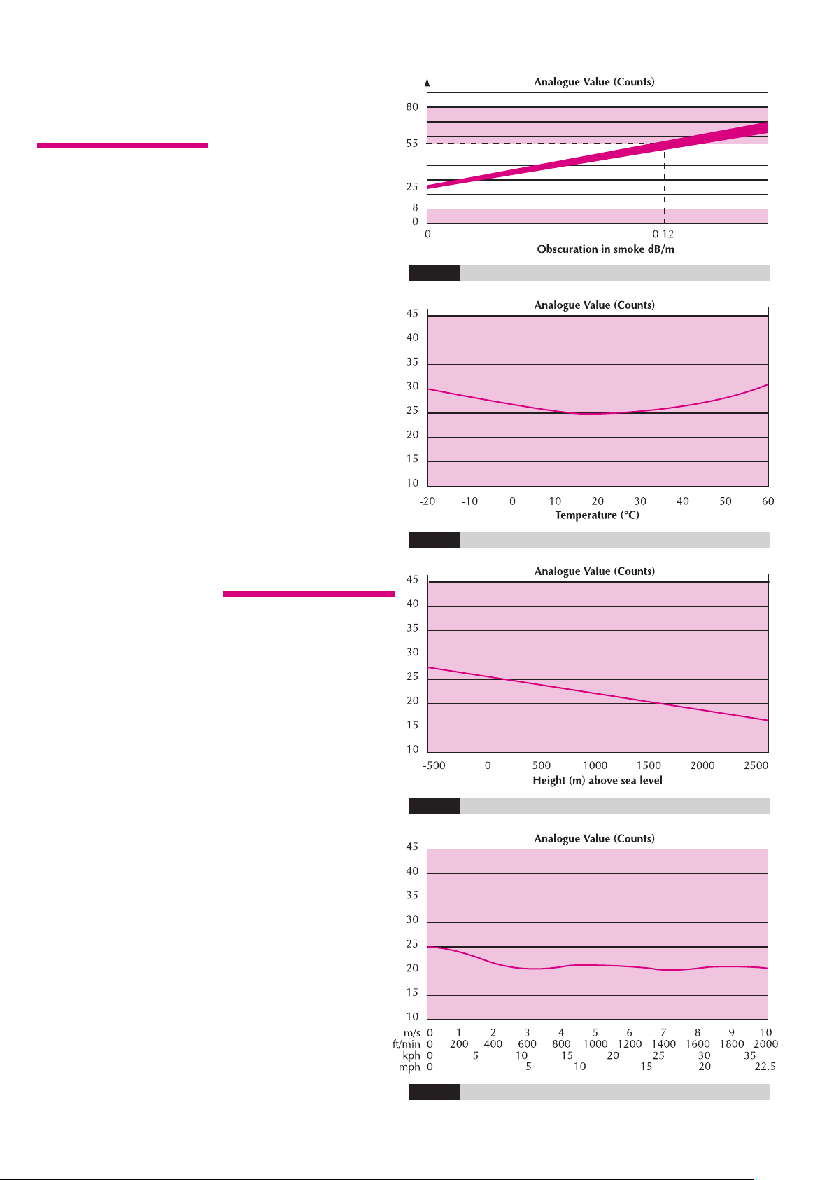
ENVIRONMENTAL
CHARACTERISTICS
The XP95 optical smoke
detector is unaffected by
wind or atmospheric
pressure and operates over
the temperature range -20°C
to +60°C. See Fig. 10.
page
9
Page 10

TECHNICAL DATA
XP95 Optical Smoke Detector
Detector Part No 55000-600/
620/660
ase Part No 45681-210
B
Specifications are typical
and given at 23°C and 50%
relative humidity unless
otherwise stated.
Detector Type:
Point type smoke detector for
fire detection and fire alarm
systems for buildings
Detection Principles:
Photo-electric detection of
light scattered in a forward
direction by smoke particles
Chamber Configuration:
Horizontal optical bench
housing an infrared emitter
and sensor arranged radially
to detect scattered light
Sensor:
Silicon PIN photo-diode
Emitter:
GaAs Infra-red light emitting
diode
Sampling Frequency:
1 second
Sensitivity:
Nominal response threshold
value of 0.12 dB/m when
measured in accordance with
N54-7:2000
E
Supply Wiring:
Two wire supply, polarity
insensitive
Terminal Functions:
L1&L2 supply in and out
+
-R remote indicator
Supply Voltage:
17 to 28 Volts dc
Quiescent Current:
340µA average, 600µA peak
Power-up Surge Current:
1mA
Duration of Power-up Surge
Current:
0.3 seconds
connections (polarity
insensitive)
R remote indicator
positive connection
(internal 2.2kΩ
resistance to supply
+ve)
negative connection
(internal 2.2kΩ
resistance to supply
- ve)
Maximum Power-up Time:
4 seconds for communications
(measured from application of
power and protocol)
10seconds to exceed10 counts
35 seconds for stable clean
air value
Alarm Level Analogue Value:
55
Clean Air Analogue Value:
25±7 counts
larm Indicator:
A
Clear light emitting diode
(LED) emitting red light
Alarm LED Current:
mA
4
Remote LED Current:
4mA at 5V (measured across
remote load)
Type Code:
(210 43) 101 00
Storage Temperature:
-30°C to +80°C
Operating Temperature:
-20°C to +60°C
Guaranteed Temperature
Range:
(No condensation or icing)
-20°C to +60°C
Humidity:
(No condensation or icing)
0% to 95% relative humidity
ind Speed:
W
Unaffected by wind
Atmospheric Pressure:
Unaffected
lectro-magnetic
E
Compatibility:
See page 21 for full details
IP Rating:
3D
2
Approvals & Regulatory
Compliance:
See page 21 for full details
Vibration, Impact & Shock:
To EN54-7:2000
Dimensions:(diameter x height)
Detector: 100mm x 42mm
Detector in Base:
100mm x 50mm
Weights:
Detector: 105g
Detector in Base: 157g
Materials:
Detector Housing: White
polycarbonate V-0 rated to
UL 94
Terminals: Nickel plated
stainless steel
page
10
technical data
0832
Fig.9 Typical Response Characteristic - XP95 Optical Smoke Detector
Fig.8 Schematic diagram - XP95 Optical Smoke Detector
Fig.10 Typical Temperature Response - XP95 Optical Smoke Detector
Page 11

XP95 HEAT DETECTOR
XP95 Heat Detector Part Number 55000-400
external air temperature.
OPERATING
PRINCIPLES
The XP95 heat detectors
have a common profile with
ionisation and optical smoke
detectors but have a low air
flow resistance case made of
self-extinguishing white
polycarbonate. The devices
monitor heat by using a
single thermistor network
which provides a voltage
output proportional to the
Fig.11 Schematic diagram - XP95 Heat detector
The standard heat detectors,
55000-400 and 55000-420,
respond to increasing air
temperature in such a way
that they are classified as an
A2S device. See figure 13.
Both devices will give 55
counts at 55°C.
A high temperature CS heat
detector, 55000-401, which
can be installed in a typical
ambient temperature of
55°C is available. See
figure 14. This device will
give 55 counts at 90°C.
Fig.12 XP95 Heat Detector
ELECTRICAL
DESCRIPTION
The detectors are designed
to be connected to a two
wire loop circuit carrying
both data and a 17V to 28V
dc supply. The detectors are
connected to the incoming
and outgoing supply via
terminals L1 and L2 in the
mounting base. A remote
LED indicator requiring not
more than 4mA at 5V may
be connected between +R
and -R terminals. An earth
connection terminal is also
provided.
When a device is energised
the ASIC regulates the flow
of power and controls the
data processing. The
thermistor provides an output
over normal operating ranges
that is proportional to the
external air temperature.
This voltage output is
processed in the A/D
converter and stored by the
communications ASIC. It is
transmitted to control
equipment when the device
is interrogated. When a
count of 55 is exceeded the
alarm flag is initiated and
the device address is added
to the data stream every 32
polling cycles from its last
polling for the duration of
the alarm level condition,
except when an alarming
device is being interrogated.
This can provide a location
identified alarm from any
device on the loop in
approximately two seconds.
The detector is calibrated to
give an analogue value of
25±5 counts at 25°C.
ENVIRONMENTAL
CHARACTERISTICS
XP95 Standard Heat
Detectors operate over the
range -20°C to +70°C, the
High Temperature Heat
Detectors operate over the
range –20°C to +120°C.
The detectors are unaffected
by atmospheric pressure.
page
11
Page 12

page
12
TECHNICAL DATA
XP95 Heat Detector
(Standard)
Detector Part No
5000-400/420
5
Base Part No 45681-210
Specifications are typical
and given at 23°C and 50%
elative humidity unless
r
otherwise stated.
Detector Type:
Point type heat detector for
fire detection and fire alarm
systems for buildings
Detector Principle:
Linear approximation over
temperature range 25°C to
90°C
Sensor:
Single NTC Thermistor
Sampling Frequency:
Continuous
Sensitivity:
25°C to 90°C: 1°C/count.
-20°C returns 8 counts
Supply Wiring:
Two wire supply, polarity
insensitive
Terminal Functions:
L1&L2 supply in and out
+R remote indicator
connections (polarity
insensitive)
positive connection
(internal 2.2kΩ
resistance to supply
+ve)
-R remote indicator
Supply Voltage:
17 to 28 Volts dc
Modulation Voltage at
Detector:
5 to 9 Volts peak to peak
Quiescent Current:
250µA average, 500µA peak
P
1mA
Duration of Power-up Surge
Current:
0.3 seconds
Maximum Power-up Time:
4 seconds
Analogue Value at 25°C
25± 5 counts
Alarm Level 55 Counts:
55°C when measured under
static conditions
Alarm Indicator:
Red light emitting diode (LED)
Alarm LED Current:
2mA
Remote LED Current:
4mA at 5V (measured across
remote load)
Type Code:
(210 43) 110 00
negative connection
(internal 2.2kΩ
resistance to supply
- ve)
ower-up Surge Current:
Storage Temperature:
-30°C to +80°C
Operating Temperature:
-20°C to +70°C
Guaranteed Temperature
Range:
(No condensation or icing)
-20°C to +70°C
Humidity:
(No condensation)
0% to 95% relative humidity
Wind Speed:
Unaffected in fixed
temperature use
Atmospheric Pressure:
Unaffected
Vibration, Impact & Shock:
To EN54-5:2000
Electro-magnetic
Compatibility:
See page 21 for full details
IP Rating:
53
Approvals & Regulatory
Compliance:
See page 21 for full details
Dimensions:(diameter x height)
Detector: 100mm x 42mm
Detector in Base:
100mm x 50mm
Weights:
Detector: 105g
Detector in Base: 157g
Materials:
Detector Housing: White
polycarbonate V-0 rated to
UL 94
Terminals: Nickel plated
stainless steel
XP95 High Temperature
Heat Detector
Detector Part No:
5000-401
5
Specifications are the same
as those for the standard
detector, apart from the
following points:
Detector Principles:
Linear approximation
designed to give 25 counts
at 25°C and 55 counts at
90°C
Sensitivity:
25°C to 90°C: 2.17°C/count
-20°C returns 20 counts.
0832
technical data
Fig.13 Typical response charateristic -XP95 Standard heatdetector
Fig.14 Typical response charateristic -XP95 Hightemperature heatdetector
Page 13

XP95 MULTISENSOR DETECTOR
XP95 Multisensor Detector Part Number 55000-885
the smoke level and the air
OPERATING
PRINCIPLES
The XP95 multisensor detector
contains an optical smoke
sensor and a thermistor
temperature sensor whose
outputs are combined to
give the final analogue value.
The multisensor construction
is similar to that of the optical
detector but uses a different
lid and optical mouldings to
accommodate the thermistor
temperature sensor. The
sectional view (Fig.15) shows
the arrangement of the optical
chamber and thermistor.
The signals from the optical
smoke sensing element and
the temperature sensor are
independent, and represent
temperature respectively in
the vicinity of the detector.
The detector’s microcontroller
processes the two signals.
The temperature signal
processing extracts only
rate of rise information for
combination with the optical
signal. The detector will not
respond to a slow temperature
increase - even if the
temperature reaches a high
level. A large sudden change
in temperature can, however,
cause an alarm without the
presence of smoke, if
sustained for 20 seconds.
The processing algorithms in
the multisensor incorporate
drift compensation. The
control panel must not have
a drift compensation
algorithm enabled.
The sensitivity of the detector
is considered the optimum
for most general applications
since it offers good response
to both smouldering and
flaming fires.
Note: in situ testing of
the multisensor should be
carried out as for smoke
detectors.
page
13
Fig.15 Sectional view - XP95 Multisensor Detector
Page 14

page
14
TECHNICAL DATA
XP95 Multisensor Detector
Detector Part No 55000-885
Base Part No 45681-210
Specifications are typical
and given at 23°C and 50%
relative humidity unless
therwise stated.
o
Detector Type:
Point type smoke detector for
fire detection and fire alarm
systems for buildings
Detector principle:
Smoke: Photoelectric
scattered by smoke
particles
Heat: Temperature-sensitive
Type code:
Bits (2 1 0 4 3)
Supply wiring:
Two-wire supply, polarity insensitive
Terminal functions:
L1&L2 supply in and out
detection of light
resistance
1 0 1 1 1
connections (polarity
insensitive)
R remote indicator
+
-R remote indicator
Operating voltage:
17-28V DC
Communications protocol:
Apollo Series 90/XP95 5-9V
peak to peak
Quiescent current:
500µA average 750µA peak
Power-up surge current:
1mA
Maximum power-up time:
10s
Alarm LED current:
3.5mA
Remote LED current:
4mA at 5V (measured across
remote load)
Clean air analogue value:
23 +4/-0
Alarm level analogue value:
55
positive connection
(internal 2.2kΩ
resistance to positive
remote indicator
negative connection)
negative connection
(internal 2.2kΩ
esistance to negative)
r
Alarm indicator:
2 colourless Light Emitting
Diodes (LEDs); illuminated
red in alarm
Optional remote LED
Electro-magnetic compatibility:
See page 21 for full details
Temperature range:
Max. continuous operating:
+60°C
Min. continuous operating:
0°C
Min. operating (no
condensation/icing): -20°C
Storage -30°C to +80°C
Humidity:
(No condensation)
0 to 95% relative humidity
Effect of temperature on
optical detector:
Less than 15% change in
sensitivity over rated range.
Slow changes in ambient
conditions will automatically
be compensated and will
not affect sensitivity
Effect of atmospheric
pressure on optical sensor:
None
Effect of wind on optical
sensor:
None
IP rating:
23D
Approvals & Regulatory
Compliance:
See page 21 for full details
ibration, Impact and
V
Shock:
To prEN54-7
Dimensions:
00mm diameter
1
50mm height
58mm (height in base)
Weight:
etector: 105g
D
Detector in base: 160g
Materials:
Housing: White
polycarbonate V-0 rated
to UL94
Terminals: Nickel plated
stainless steel
Smoke element only:
Chamber configuration:
Horizontal optical bench
housing infra-red emitter
and sensor, arranged
radially to detect forward
scattered light
Sensor:
Silicon PIN photo-diode
Emitter:
GaAlAs infra-red light
emitting diode
Sampling frequency:
1 per second
technical data
WARNING: if the control panel incorporates a drift compensation algorithm,
this should be disabled when polling the XP95 Multisensor detector.
Page 15

XP95 MANUAL CALL POINT
XP95 Manual Call Point (MCP)
OPERATING
PRINCIPLES
The new Apollo XP95 EN5411:2001 compliant Manual
Call Point (MCP) is based on
the KAC conventional MCP
range. It is electronically
and mechanically backward
compatible with previous
Apollo call points based on
KAC’s World Series product.
The address of each call
point is set at the
commissioning stage by
Colour Deformable Backbox Pattress Isolated Non-
Fig.16 Typical response characteristic - XP95 Manual Call Point
means of a seven-segment
DIL switch.
A single bi-coloured alarm
LED is provided on the call
point. This LED is controlled,
independently of the call
point, by the control panel.
The red LED is lit when the
call point has been activated.
An amber/yellow LED
indicates a fault.
Call points can be remotely
tested from the panel by
transmission of a single bit
in the communications
protocol. Call points
respond by providing a
Element for surface Box isolated
Wiring
value of 64 which
corresponds to the alarm
value. The panel should
recognise this response as a
test signal and should not
raise a general alarm.
XP95 Manual Call Points are
available with or without an
isolator. Each version is
available with a resettable
element and a backbox for
surface mounting as standard.
If a glass or flush mounting
tray is required, these are
available on request.
Versions with a pattress box
are also available with and
without an isolator. For all
part numbers please refer to
Table 2.
To provide additional
protection against accidental
operation, a transparent
hinged cover with a locking
tag, part number 26729-152
is available, which can be
fitted to the manual call
point. Please note that the
call point dos not conform
to EN54-11:2001 when this
lid is fitted and secured with
the locking tag.
Important Note – the use
of lubricants, cleaning
solvents or petroleum
based products should be
avoided.
page
15
55100-905 Red •• •
55100-907 Red •••
55100-908 Red •• •
55100-909 Red •••
Table2
Page 16

page
16
TECHNICAL DATA
XP95 Manual Call Point
Specifications are typical
and given at 23°C and 50%
relative humidity unless
otherwise stated.
Call Point Type:
eformable element
D
Weight:
151g
Call Point Principle:
Operation of a switch
Alarm Indicator:
Red Light Emitting Diode (LED)
Fault Indicator:
Amber/yellow light emitting
diode (LED)
Type Code:
(2 1 0 4 3)
1 1 1 1 1
Supply Wiring:
Two-wire supply, polarity
sensitive
Loop connections L1/L2:
Terminal block
Operating Voltage:
17V-28V dc
Communication Protocol:
5V-9V peak to peak
uiescent Current:
Q
100µA
Power-up Surge Current:
1mA
aximum Power-up Time:
M
1 second
Alarm Current, LED
illuminated:
mA
4
Normal Analogue Value:
16
Alarm State Value:
64
Electro-magnetic
Compatibility:
See page 21 for full details
Temperature Range:
Max. continuous operating:
Min. continuous operating:
Min. operating: -20°C
(no condensation/icing)
Storage: -30°C to +80°C
+60°C
0°C
Humidity:
(No condensation)
to 95% relative humidity
0
Compliance Standard:
EN54-11:2001
EN54-17:2005 (isolated
ersion)
v
IP Rating:
24
Dimensions:
9mm x 93mm x 26.5mm
8
(manual call point)
87mm x 87mm x32mm
(back box)
Materials:
Housing: Red self-coloured
Polycarbonate/ABS
Hinged cover and locking
tag are also available, part
number: 26729-152
XP95 glasses are also
available, part number:
26729-154 (pack of 5)
technical data
Page 17

XP95 MOUNTING BASE
Fig.17 Schematic wiring diagram - XP95 mounting base
XP95 Mounting Base Part Number 45681-210
The remaining single terminal
XP95 Mounting Bases and
XPERT cards.
The XP95 smoke and heat
detectors all fit the XP95
mounting base. The base is
a zero insertion force base
with dual finger receptacles
of stainless steel into which
the detector terminals slide.
Cable connections of up to
2.5mm diameter are made
via captive cable clamps.
There are four double
terminals and one single one.
L1 line IN and OUT,
double terminal
L2 line IN and OUT,
double terminal
+R remote LED positive
supply, double terminal
-R remote LED negative
supply, double terminal
is isolated and can be used
to provide continuity of an
earth or shield.
Universal address cards,
known as XPERT cards are
supplied with all bases.
Consult the coding guide to
determine which pips are to
be removed. Pre-printed and
pre-punched address cards
that save time and increase
accuracy during
commissioning are
available in sets, part
number: 38531-771
The base has a ‘one way
only’ fit and detectors can
be locked into the base by a
grub screw with the aid of a
1.5mm hexagonal driver,
part number: 29600-095.
For more information on
Apollo’s range of bases,
please refer to the Range of
Bases & Mounting Accessories
brochure, PP1089.
Fig.18 Schematic wiring diagram of XP95 detector circuit with a
common remote LED
page
17
Page 18

XP95 20D ISOLATING BASE
page
18
XP95 20D Isolating Base Part Number 45681-284
OPERATING
PRINCIPLES
The XP95 20D isolating base
senses and isolates short
circuit faults on XP95 loops
and spurs. The base is loop
powered, polarity sensitive
and accepts the XPERT card
to set the associated device
address.
In short circuit conditions
the integral yellow LED is
illuminated. The detector
associated with the base
remains active under short
circuit conditions. Power
and signals to the affected
section are restored
automatically when the
fault is cleared.
ELECTRICAL
DESCRIPTION
Under normal operating
conditions, a low impedance
is present between the –IN
and –OUT terminals of the
base, so that power and
signals pass to the next
base in the line.
If a short circuit or abnormally
low impedance occurs, the
fall in voltage is sensed and
the base isolates the negative
supply in the direction of
the fault.
In applications where it is not
necessary to use an isolating
base for each detector, up to
twenty devices (detectors
and XP95 interfaces) may be
installed between isolating
bases, provided that their
TECHNICAL DATA
XP95 20D Isolating Base
Device Part No:
45681-284
Maximum Loop Operating
Voltage:
28V DC plus 9V protocol
pulses
Minimum Normal Loop
Operating Voltage:
17V DC
Power-up Time:
>10mS
Isolation time, 2Ω load at
28V:
20µs
Isolation Voltage:
14V
Isolation Indicator:
Yellow LED, lit continually
in isolation condition
Current Consumption:
at 18V 23µA
at 28V 43µA
at 18V and adjacent
sector isolated 4mA
total switch-on surge current
doesnotexceed 20mA.
Circuits may include spurs,
which should be connected
between the spare –OUT
terminal and the base L2
terminal. Spurs connected
in this way appear directly
across the loop on the
output side of the isolating
base. Short-circuit faults
on the spur therefore short
circuit the loop and vice
versa. The effect of such
short circuits must be taken
into account in the system
design and may require the
use of extra isolating bases.
For further information on
the use of XP95 isolators,
please refer to PP2090 Short
Circuit Isolation in XP95
and Discovery Fire Systems.
Maximum Line Current:
Non-isolatingcontinuous 1.0A
Transition into isolation 3.0A
On Resistance:
<0.2Ω
Device Reset Resistance:
300Ω
EMC:
ee page 21 for full details
S
Operating Temperature:
-20°C to +60°C
Storage Temperature:
-30°C to +80°C
Relative Humidity (no
condensation/icing):
0% to 95%
Dimensions:
100mm (diameter) x 24mm
(height)
100mm (diameter) x 60mm
(height) base with detector
fitted
Weight:
100g
Page 19

XP95 ISOLATOR
MINIDISC REMOTE INDICATOR
LOOP-POWERED SOUNDERS.FLAME DETECTOR
.
LOOP-POWERED BEAM DETECTOR
P95 ISOLATOR
X
Part Number: 55000-720
Base Part Number: 45681-211
‘Stand-alone’ isolators,
which have their own bases,
may be used instead of
isolating bases. The
isolators are wired to a loop
between detectors or other
devices.
XP95 LOOP-POWERED
BEAM DETECTOR
Part Number: 55000-265
The XP95 optical beam
detector has been designed
to protect large open spaces
such as museums, churches,
warehouses and factories. It
consists of three main parts:
the transmitter, which projects
a beam of infra-red light,
the receiver, which registers
the light and produces an
electrical signal, and the
interface, which processes
the signal and generates
alarm or fault signals.
The transmitter and receiver
are designed to be fitted on
opposite walls approximately
30cm to 60 cm below the
level of the ceiling. They
can protect an area up to
100m long and 15m wide,
a total of 1500m
The interface contains the
electronic circuitry needed
to control the beam detector
and communicate with the
control panel via the XP95
loop.
The beam detector is looppowered and needs no
separate 24V supply. This
not only eliminates the need
for additional equipment, it
also saves both cost and
time in installation.
2
.
NTELLIGENT REFLECTIVE
I
BEAM DETECTOR
Part Numbers:
55000-268 (5-50m)
5000-273 (50-100m)
5
The intelligent reflective
beam detector is a compact
detector for detecting smoke
in large open areas such as
atria, warehouses, theatres
and churches. It also has a
built-in 20D negative bidirectional short circuit
isolator.
The transmitter and receiver
form a single unit mounted
to a wall of the building. A
reflector which returns the
IR beam from the transmitter
to the receiver is mounted
on the opposite wall. In the
event of smoke partially
obscuring the light an
imbalance between the
transmitted and received
light will occur. On
interrogation by the control
panel the detector will then
transmit an alarm value.
The intelligent reflective
beam detector is an addition
to the Apollo range and not
a replacement for the XP95
loop-powered beam
detector.
The intelligent reflective
beam detector is supplied in
two versions: one for use at
distances of 5–50m from
detector to reflector and the
other for distances of 50–
100m.
The detector is non-latching
and resets 30 seconds after
an alarm event ceases and
in 3 seconds after the
removal of a fault.
A termination backbox, part
no 29600-241, is available.
This allows easy first fixing of
he cabling and terminations
t
to the intelligent reflective
beam detector. The
termination backbox can
be surface or flush mounted.
MINIDISC REMOTE
INDICATOR
Part Number: 53832-070
A light-weight, compact
indicator for use in fire
protection systems. The
indicator may be used in all
installations incorporating
Series 60, XP95, Discovery
and Intrinsically Safe
detectors. It is only 20mm
high and 80mm in diameter.
It comprises two parts – the
base, which is installed onto
a wall or soffit and the lid,
which is fitted to the base
with a bayonet lock.
LOOP-POWERED
SOUNDERS, BEACON &
SOUNDER BEACONS
There are two types of looppowered sounder available,
allowing fire engineers to
specify not only the sound
output but also the
functionality of individual
sounders.
The 85dB(A) Low-Profile
loop sounder is intended for
use in confined spaces such
as hotel rooms and corridors.
It is designed to have a base
and detector mounted upon
it, but can also be used as a
stand-alone sounder. The
100dB(A) loop sounder is
intended as an open-space
sounder, where a higher
output is required.
larms may be signalled
A
visually by means of a
flashing beacon. Combined
sounder beacon units are
available where both
udible and visual signalling
a
is required.
The following types of
device are available:
Ancillary Base Sounder
Part Number: 55000-276
A local-area sounder with
an integral base for a
detector head. The sounder
is switched by the detector
remote output and needs no
address of its own. Sound
output 85dB(A) at 1 metre.
Integrated Base Sounder
Part Numbers:
45681-278 (sounder)
45681-291 (slow whoop)
45681-277 (with isolator)
45681-290 (slow whoop
with isolator)
45681-292 (white cap)
45681-293 (red cap)
A sounder with two volume
ranges 55–75dB(A) and
75–91dB(A) which
incorporates a detector
base. It is supplied with a
built-in isolator and ‘alert’
and ‘evacuate’ tones. A
version with a Dutchstandard slow whoop is
also available.
page
19
Page 20

page
20
ntegrated Base Sounder
I
(DIN Tone)
Part Number: 45651-300
A sounder with an integral
detector base configured
to the requirements of
German standard
DIN33404, Part 3.
Loop-powered 100dB(A)
Sounder
Part Numbers:
55000-276 (slow whoop,
red)
55000-277 (slow whoop,
white)
55000-274 (weatherproof,
red)
55000-275 (weatherproof,
white)
55000-278 (red)
55000-279 (white)
Designed for use in
open areas this sounder is
available in red or white.
The weatherproof version is
also available in red and
white. The indoor version
may be ordered with a
Dutch-standard slow whop
tone.
oop-powered Beacon
L
Part Numbers:
55000-877 (red lens)
55000-878 (clear lens, red
lash)
f
55000-879 (amber)
The beacon has been
developed to alert those
with hearing difficulties and
to be used in areas with a
high background noise
level. The beacon is fitted
to any XP95 or Discovery
base.
Beacon Enclosure
Part Number: 29600-318
This is an enclosure with a
clear lid and which has an
IP rating of 67, allowing a
beacon to be fitted for use
outdoors.
Sounder Beacon Base
Part Numbers:
45681-330 (with isolator)
45681-331
45681-332 (slow whoop
with isolator)
45681-292 (white cap)
45681-293 (red cap)
ulti-tone Open-area
M
Sounder Beacons
Part Numbers:
55000-293 (with isolator,
ed)
r
55000-298 (weatherproof,
with isolator, red)
Audio-visual fire alarm
devices for large open areas.
Sound output is nominally
100dB(A). The product
features selectable tones,
thus minimising the
number of regional variants
required. Available in red
or white, indoor use or
weatherproof, with or
without isolator.
XP95 FLAME DETECTOR
Part Number: 55000-280
Operating Principles
An infrared sensor designed
to detect specific types of
flame, making it immune
to solar radiation and other
nuisance sources of infrared.
The detector is rated at
IP65, uses XP95 protocol
and is loop powered –
eliminating the need for a
separate power supply.
This device combines a
local-area sounder and a
flashing beacon. It has an
integral isolator and base for
a detector head. Detection
is thus co-located with both
audible and visual alarms
and short circuit isolation.
Page 21

XP95 APPROVALS & REGULATORY COMPLIANCE
EMC
APPROVALS AND REGULATORY
COMPLIANCE
he XP95 range of detectors and manual call points is
T
approved by a large number of third party certification
bodies around the world. These include detector approvals
to EN54:2000 with LPCB, VdS, DIBT, BOSEC and FG and
to UL 268 and 521 with UL. For further information and
updates on approvals held by Apollo for the XP95 range,
contact the company directly or see our website,
www.apollo-fire.co.uk
XP95 detectors comply with the requirements of a number
of European New Approach Directives, such as the EMC
Directive 89/336/EEC and the Construction Products
Directive 89/106/EEC. Copies of EC certificates of
conformity issued by LPCB as a Notified Body under the
Construction Products Directive are available from our
website www.apollo-fire.co.uk or directly from Apollo.
In addition, copies of Declarations of Conformity issued
by Apollo for all applicable New Approach Directives are
available upon request.
All XP95 products will comply with the marking
requirements of the WEEE Directive, 2002/96/EC. For
further information on disposing of applicable electrical
and electronic waste, contact Apollo directly.
EMC
All XP95 detectors and manual call points comply with the
equirements of the following EMC standards:
r
Generic Emission Standard EN 61000-6-3
Emission standard for residential, commercial and light
industrial environments.
Generic Emission Standard EN 61000-6-4
Emission standard for industrial environments.
EN 50130-4 : Alarm Systems
Electromagnetic compatibility - product family standard :
Immunity requirements for components of fire, intruder and
social alarm systems
EN 6100-4-2
Electrostatic discharge
EN 6100-4-3
Radiated immunity
EN 6100-4-4
Fast transient bursts
EN 6100-4-5
Surge immunity
EN 6100-4-6
Conducted immunity
In addition, all of the XP95 detectors have been assessed to
the additional VdS EMC requirements, which are shown
below and have been demonstrated full compliance.
Additional VdS requirements:
30V/m with 80% Am sine and 100% pulse modulation
depth over the frequency ranges 415 to 467MHz and 890
to 960MHz.
page
21
Page 22

MAINTENANCE OF DETECTORS
Apollo Fire Detectors has published a guide to the
care, maintenance and servicing of Apollo products,
P2055, which is available on request. This guide
P
outlines the maintenance routines recommended for
optimum detector performance and the services
available from Apollo’s factory-based Service
Department.
page
22
Page 23

page
23
Page 24

PP1039/2006/Issue 8a
For more information on any of the products mentioned in this engineering guide, please refer to
the following literature which is available on request.
Publication Name Publication Number
ompatible Panel Manufacturers PIN Sheet PP1010
C
Range of Bases & Mounting Accessories Brochure PP1089
XP95 20D Isolating Base PIN Sheet PP2039
A Guide to the Care, Maintenance and Servicing of Apollo Products PP2055
XP95 Range of Interfaces Brochure PP2025
XP95 Switch Monitor PIN Sheet PP2015 (std enclosure)
PP2048 (DIN-rail enclosure)
PP2084 (with isolator)
Mini Switch Monitor PIN Sheet PP2021
ini Switch Monitor with Interrupt PIN Sheet PP2020
M
Switch Monitor Plus PIN Sheet PP2014 (std enclosure)
PP2047 (DIN-rail enclosure)
PP2083 (with isolator)
Zone Monitor PIN Sheet PP2016 (std enclosure)
PP2049 (DIN-rail enclosure)
PP2101 (with isolator)
Sounder Control Unit PIN Sheet PP2019 (std enclosure)
PP2050 (DIN-rail enclosure)
PP2094 (with isolator)
Input/Output Unit PIN Sheet PP2017 (std enclosure)
PP2045 (DIN-rail enclosure)
PP2092 (with isolator)
Output Unit PIN Sheet PP2018 (std enclosure)
PP2046 (DIN-rail enclosure)
PP2093 (with isolator)
XP95 Mains Switching Input/Output Unit PIN Sheet PP2107
Dual Isolator PIN Sheet PP2051 (DIN-rail enclosure)
XP95 Three Channel Input/Output Unit PIN Sheet PP2121
MiniDisc Remote Indicator PIN Sheet PP2074
XP95 Loop-Powered Beam Detector Sales Leaflet PP2078
XP95 Flame Detector Sales Leaflet PP2111
XP95 Flame Detector PIN Sheet PP2110
Short Circuit Isolation in XP95 and Discovery Fire Systems PP2090
Intelligent Reflective Beam Detector PP2155
Ancillary Base Sounder PP2148
Integrated Base Sounder PP2209
Integrated Base Sounder (DIN Tone) PP2227
Loop-powered 100dB Sounder PP2082
Loop-powered Beacon PP2156
Beacon Enclosure PP2204
Sounder Beacon Base PP2235
Multi-tone Open-area Sounder Beacon PP2256
© Apollo Fire Detectors Ltd 1999 - 2006
Assessedto ISO 9001: 2000
Certificate number 010
36 Brookside Road, Havant, Hampshire PO9 1JR, UK. Tel: +44 (0)23 9249 2412. Fax: +44 (0)23 9249 2754.
Email: sales@apollo-fire.co.uk Website: www.apollo-fire.co.uk
Apollo GmbH, Am Anger 31, 33332 Gütersloh, Germany. Tel: +49 5241 33060. Fax: +49 5241 330629
 Loading...