

Page 1
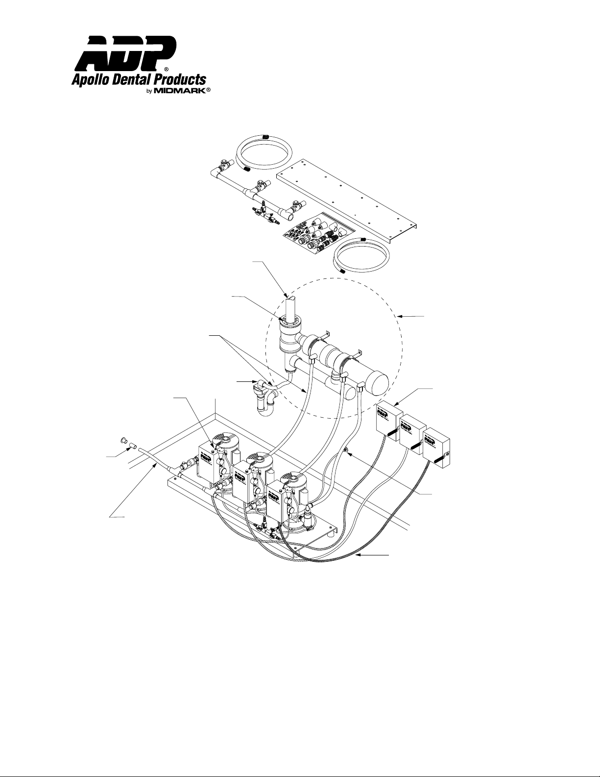
2" PVC Vent Pipe
(Provided By Plumber)
2" PVC Vent Connection
3/4" x 3" Flex PVC Exhaust Line
"Use PVC Glue"
(Provided)
Installation Instructions
Twin Vacuum To Triple Vacuum
Conversion Kit
Part #AVA85195
Water Separator
(#AVAVXS3)
(Not Provided)
1 1/2" "P"-Trap With 1" Air Gap
(Provided By Plumber)
Low Voltage Wires For
24V Remote Operation
(Red And Blue Switching)
White = Light
PVC Slip
Coupling And
MPT Adapter
(Provided)
(Refer To Local Plumbing Codes)
1 1/4" x 4' Flex PVC
Inlet Tubing
"Use PVC Glue"
(1 1/2" x 4' Flex PVC On
Triple 2 Or 3 HP Models)
(Provided)
CAUTION: Never Operate Equipment Without Complete And Proper Grounding.
6' Conduit
(Provided)
Disconnect Boxes
(Provided By Electrician)
1/4" x 8' High Pressure
Water Inlet Hose With
Water Control Valves
Located On Platform
(1/2" Or 1/4" MPT Or 3/8" Tube)
(Provided) See Note
Description:
Apollo Dental Products Vacuum Systems Triple Conversion Kit was developed to allow for expansion of an existing Apollo Twin
Vacuum System to a triple vacuum system in the event vacuum needs outgrow current capacity. The kit includes: intake manifold,
check valve assembly, exhaust hose elbow assembly, water supply assembly, mounting plate, and all the plumbing and hardware
necessary to make the conversion. The kit is an attractive alternative to simply replacing the system in that it offers substantial cost
savings. It is important when upgrading a system, to use pumps of equal horsepower and construction. Failure to do so will result in
poor performance and premature failure.
Apollo Dental Products, Inc. • 245 W. Dakota Ave. • Clovis, CA 93612 • Technical Support
559/292-1444 • 800/233-4151 • Fax 559/292-1555 • www.apollodental.com
Page 1
AMI60396 Rev. 8/02
Page 2

Installation Instructions
Twin Vacuum To Triple Vacuum
Conversion Kit
Technical Service - (800) 233-4151
Installation:
1. Turn power OFF to vacuum at main circuit breaker panel.
2. Place the ON/OFF valve at the water supply manifold in the “OFF” position and disconnect water supply poly-flow lines from
the ON/OFF supply manifold..
3. Disconnect exhaust lines from either the sewage termination, or exhaust separator.
4. Remove pumps from the twin mounting base and retain all mounting hardware.
5. Using the 5/16” x 1 1/4” long bolts, mount all three pumps onto the triple platform with the 1/4” x 5/16” ID spacers between
the pumps and the mounting plate.
NOTE: Elevate the platform solidly - approximately 3 to 4 inches for easy access to pump mounting hardware.
6. Remove rubber feet from twin mounting plate and install same feet on triple mounting plate.
7. Remove the straight poly-flow connector from the water supply manifold tee.
8. Insert the provided street tee assembly with poly-flow elbow into end of water supply manifold. Re-install the straight poly-flow
connector into the end of the new manifold.
9. Connect poly-flow tube line from pump water strainer inlet fittings to new water supply manifold.
10. Remove the hose adapter fitting from the new pump exhaust and install the new exhaust hose elbow assembly into it’s
exhaust outlet
11. Attach 3/4” flex tube PVC exhaust/drain hoses to a exhaust separator or sewage connection and glue with PVC type cement.
A triple exhaust separator kit may be required (#AVAVXS3).
12. Connect high voltage electrical supply line to the new pump as indicated in the electrical diagram. See pump Installation
Manual pages 4 and 5.
13. For low voltage remote control of the individual pumps, an ADP Triple Vacuum Master Control Panel is required to operate
third vacuum unit. Wire 3rd switch red to red and blue to blue, connect white for light.
Using a two vacuum switch panel, connect the red and blue low voltage wires to the new pump to red and blue wire
connections of the middle pump. Do not connect the white low voltage wire.
14. Install the check valve assembly into the new vacuum pump strainer.
15. Push on the triple vacuum intake manifold, glue with PVC type cement and connect the vacuum line from operatories.
16. Switch vacuum main circuit breaker ON. Each pump should be started separately to check performance and there are no leaks.
17. Check exhaust tubing to ensure that water is flowing through the pumps.
IMPORTANT: Do not run pump without full pressure water supply as serious pump seal damage will result.
18. Check vacuum gauge to ensure that the pump is functioning properly. Vacuum relief is factory preset for 10 inches Hg vacuum.
All relief valves should be set for the same vacuum relief pressure.
Warranty Information: 90 Days
All ADP accessories are thoroughly inspected and tested in accordance with rigid specifications and standards. Our accessories are guaranteed
against any defective material and workmanship from the date of shipment; provided that the installation, operation, and maintenance is done in
accordance with ADP procedures as outlined in our Installation and Maintenance Guides. Warranty cards must be returned to ADP within ten days of
installation to effect warranty. No other warranties or guarantees, expressed or implied are made.
ADP’s obligation under the warranty is to provide parts for the repair or, at its option, to provide the replacement product (excluding labor). All
special, incidental and/or consequential damages are excluded. We will not issue credit for accessories without first attempting to correct the
problem in the field. Written notice of breach of warranty must be given to ADP within the warranty period. The warranty does not cove damage
resulting form improper installation or maintenance, accident or misuse. The warranty does not cover damage resulting from the use of cleaning,
disinfecting or sterilizing chemicals and processes. The warranty does not cover vacuum failures due to hard water deposits. Failure to follow
instructions provided in ADP’s Installation and Maintenance Guides may void the warranty.
Page 2 AMI60396 Rev. 8/02
 Loading...