

Page 1

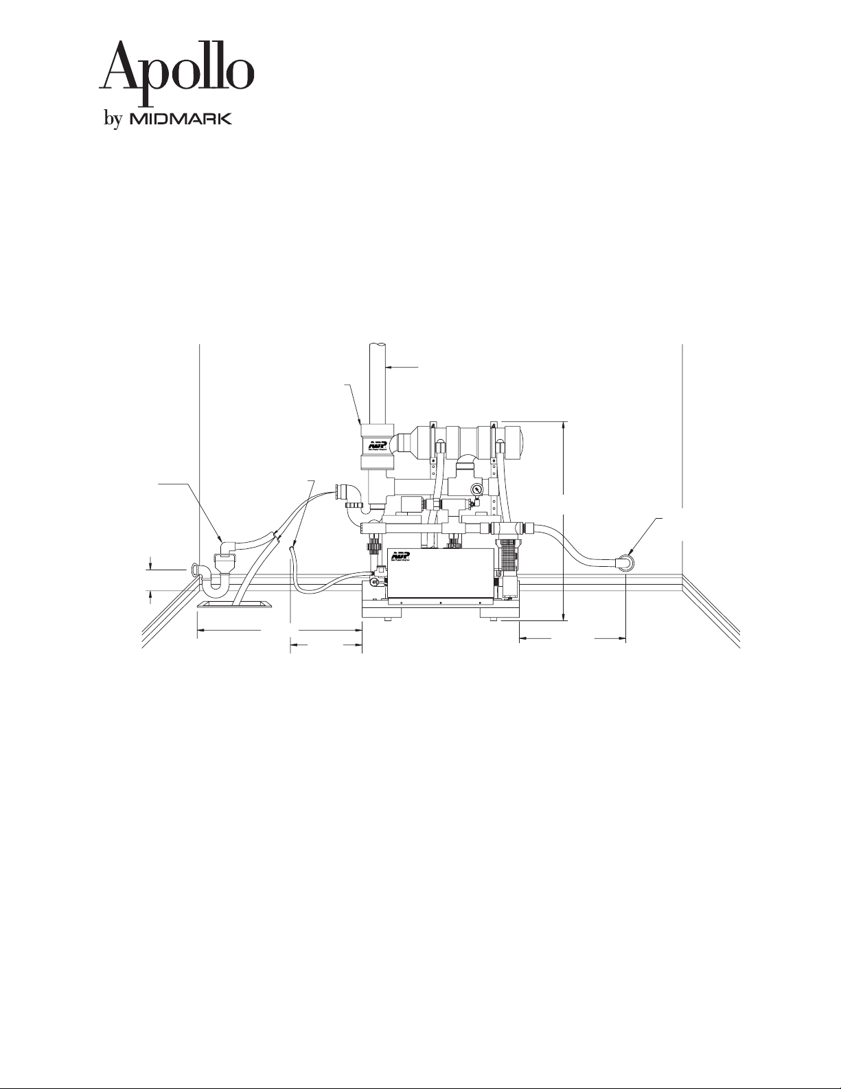
2" PVC Vent Pipe
(Provided By Plumber)
2" PVC Vent Connection
(Vent To Outdoors)
Installation & Operation
Twin Vacuum System
1/4" x 8' High Pressure Water Inlet Hose with
Water Control Valves Located On Platform
(1/2" or 1/4" MPT Fittings Provided)
See Note On Local Codes
1 1/2" P-Trap With 1" Air Gap
(Provided By Plumber)
(Refer To Local Plumbing Codes)
Low Voltage Wires For
24V Remote Operation
(Red and Blue Switching)
White = Light
"ON/OFF" 1/2 Amp Circuit Breaker
Switches (Provided)
Lifting Handle Receiver
NOTE: Some Local Codes Require A Reduced Pressure (RP) Backflow Preventor
On The Incoming Water Line. (Not Provided)
Optional Wall Mounting
(Extra Hose Provided)
Air / Water Separator
(Provided With Separator Models)
Disconnect Box
(Provided By Electrician)
(1 Circuit Per Pump)
6' Conduit (Provided)
1" x 4' Flex PVC Inlet Tubing
(Do Not Cement)
(1 1/4" x 4' Flex PVC On Twin
2 Or 3 HP Models) (Provided)
1" PVC Slip Coupling
and MPT Adapter (Provided)
Description:
Apollo Vacuum Systems have been tested and approved by various regulatory test agencies. The following list contains Apollo File
Numbers that may be helpful if questions arise regarding installation inspections.
Underwriter’s Laboratories (UL) (cUL) ..................... File Number: MH13627
U.S. Food and Drug Administration (FDA)................. File Number: 2937927
City of Los Angeles Mechanical Test Labs................. File Number M880066
This dental vacuum system should only be installed by qualified personnel. Should any questions arise during the installation, call
Apollo Technical Support between the hours of 7:00 a.m. to 4:00 p.m. (Pacific Standard Time).
Unpacking The System:
Place the Vacuum System in a clean, dry, well ventilated area, on a solid, level surface. Consider sound level and insulate as needed.
Be sure that adequate ventilation is available as the Vacuum System is air-cooled. Ambient temperature in the equipment room should
be within the temperature range of 40 degrees Fahrenheit (4o C) minimum to 100 degrees Fahrenheit (38o C) maximum.
Do Not Allow The Vacuum To Freeze.
1. Remove the cardboard from the shipping platform.
2. Inspect pump for freight damage and confirm that the Pump Installation Kit is in the box.
3. Remove the pump from the shipping platform.
Apollo by Midmark • 60 Vista Drive • Versailles, Ohio 45380 • Technical Support
1-800-MIDMARK • Fax 877-249-1793 • www.midmark.com
Page 1
AMI60333 Rev. 4/03
Page 2

Installation & Operation
Twin Vacuum System
Vacuum Pump Specifications:
Model Max Width Depth Height Shipping Total Volt Amperage Hz Wire Breaker
Users *** Weight HP (Per Pump) GA* Size**
AVG10TNFX / AVU10TNFX 6 66 cm 44 cm 76 cm 64 kg 2 220 8.1 50 14 2@20
AVG10TNX / AVU10TNX 6 26 in 18 in 30 in 140 lb 2 115/208-230 16.2/8.1 60 10/14 2@30/2@20
AVB10TN* 5 26 in 18 in 20 in 140 lb 2 115/208-230 16.2/8.1 60 10/14 2@30/2@20
AVB10TNFX 5 66 cm 44 cm 76 cm 66 kg 2 220 8.1 50 14 2@20
AVB10TNX 5 26 in 18 in 30 in 145 lb 2 115/208-230 16.2/8.1 60 10/14 2@30/2@20
AVG15TNFX / AVU15TNFX 7 66 cm 44 cm 76 cm 70 kg 3 220 11 50 14 2@20
AVG15TNX / AVU15TNX 7 26 in 18 in 30 in 115 lb 3 208-230 11 60 14 2@20
AVB15TN* 6 26 in 18 in 20 in 155 lb 3 208-230 11 60 14 2@20
AVB15TNFX 6 66 cm 44 cm 76 cm 73 kg 3 220 11 50 14 2@20
AVB15TNX 6 26 in 18 in 30 in 160 lb 3 208-230 11 60 14 2@20
AVB20TNX 8 26 in 18 in 32 in 165 lb 4 208-230 12.4 60 14 2@20
AVG20TNFX / AVU20TNFX 10 66 cm 44 cm 81 cm 75 kg 4 220 12.4 50 14 2@20
AVG20TNX / AVU20TNX 10 26 in 18 in 32 in 165 lb 4 208-230 12.4 60 14 2@20
AVG30TNFX / AVU30TNFX 12 66 cm 44 cm 81 cm 80 kg 6 220 14 50 14 2@30
AVG30TNX / AUG30TNX 12 26 in 18 in 32 in 175 lb 6 208-230 14 60 14 2@30
For Recycler option, add “R” to last prefix only. Example: AVB10TNR.
*Non separator models, VB10TN and VB15TN, are not recommended for single pump operation.
** Each pump requires a separate electrical circuit.
*** Height with Exhaust Separator
Dual Voltage Models
Blu
Red
Wht
Blu
Red
Wht
1/2 Amp
ON / OFF
Circuit Breaker Switch
Blu
Blu
Wht
Red
Yel
Yel
Blk
Motor Leads
Blu
Brn
Blu
Blu
Blu
Red
Vio
Blu
Yel
Blk
Red
Yel
Vio
3567
2
GRD
115 Volt Supply To Terminals
1 and 4
Install Jumpers From Terminals:
3 to 4
5 to 6
7 to 8
1/2 Amp
ON / OFF
Circuit Breaker Switch
Motor Leads
Blu
Blu
Brn
Blu
Blk
Vio
Wht
Blk
Yel
Yel
Blu
Wht
Brn
Yel
8
230 Volt Supply To Terminals
1 and 2
Install Jumpers From Terminals:
2 to 3
6 to 7
Third Jumper Not Required
Blu
Red
See Low Voltage Control
Wht
Blu
Wht
Blu
Red
115 or 230V Primary
Red
Transformer
24VAC Secondary
Blu
Blu
Yel
Wht
Wht
Org
Wht
Blk
Vio
Blu
Blk
Blu
Wht
Org
Wht
56 78
34
GRD
(FACTORY SETTING)
Blk
Wht
Solenoid Coil
GRD
Remote Lighted
Switch
Solenoid Coil
GRD
Blu
Red
Wht
LOW VOLTAGE CONTROL
See Low Voltage Control
Wht
Blk
Blk
Wht
Wht
Wht
Blu
Blk
Org
Wht
Blk
Blu
Vio
Yel
24VAC Secondary
Blk
Transformer
Wht
115 or 230V Primary
Org
IMPORTANT: All Vacuum Systems are to be installed according to local plumbing and electrical codes.
Never operate the equipment without complete and proper grounding.
Page 2
Page 3

Single Voltage Models
Installation & Operation
Twin Vacuum System
Technical Service - (800) 233-4151
Remote Lighted
Switch
Solenoid Coil
GRD
Blu
Red
Wht
LOW VOLTAGE CONTROL
See Low Voltage Control
Wht
Blk
Blk
Wht
Wht
Org
Blu
24VAC Secondary
Org
Wht
Transformer
230V Primary
Blu
Red
Wht
GRD
230 Volt Supply To Terminals
Blu
Red
Wht
Brn
1/2 Amp
ON / OFF
Circuit Breaker Switch
Blu
Wht
Blu
Blu
Brn
Wht
Wht
Blu
Blk
Wht
1/2 Amp
ON / OFF
Circuit Breaker Switch
Wht
Blu
Blu
Red
Wht
Yel
Motor Leads
Blu
Red
Brn
Blu
Blu
Red
Motor Leads
Blu
Blu
Red
See Low Voltage Control
Wht
Blu
Wht
Blu
Red
Wht
230V Primary
Yel
Transformer
24VAC Secondary
Yel
Blk
Wht
Blu
Org
Wht
Wht
Red
Blk
Wht
Wht
Wht Org
Solenoid Coil
GRD
A. Electrical Hook-Up Requirements:
Low Voltage Line (24V)
18-3 Thermostat wire from each remote control switch to each vacuum; if low voltage remote control switching is
desired. Red and Blue wires are for switching, the White wire is for a lighted switch, paired with Red.
Line Voltage (60 Hz)
Two, single-phase, 115 or 208-230 volt, 60 Hz, supply circuit with approved ground connection required. The 1HP units
are dual voltage 115/208-230 volt. The 1 1/2, 2 and 3HP units are 230 volts only. All units are factory wired for
208-230 volt operation: 208-230 volt operation is recommended for maximum efficiency.
Line Voltage (50 Hz)
Two, single phase, 220 volt, 50 Hz., supply circuit with approved ground connection is required. All units are factory
wired for 220 volt operation: 220 volt operation is recommended for maximum efficiency.
B. Plumbing Hook-Up Requirements: (See Illustration on Page 1)
Water Line
1/2 inch (13mm) cold water supply line with shut off valve terminating in 1/2 inch (13mm) FPT. The line must be
flushed out with 5 gallons of water prior to connection to vacuum.
IMPORTANT: Water is essential for the operation and longevity of the pump. The supply must not be restricted or
interrupted during operation. Water with high mineral content may cause mineral build-up and create water starvation, leading to seal failure. A water softener and filter are recommended for this situation. (*To prevent gradual
buildup, use StayClean™ Mineral Deposit Remover)
Waste Line
Water drains to sewer terminating in:
Option A - Floor sink.
Option B - P-trap adapted to 3/4 inch (19mm) PVC slip connection, A 1 inch (25mm) air gap may be required by local code.
Page 3
Page 4

Air Vent
2 inch PVC air vent to outdoors. Do not cap vent, serious back pressure may result in pump failure.
Vacuum Line (Do Not Cement)
1 inch (25mm) PVC female slip connection. 2 and 3 HP models require a 1 1/4 inch (38mm) PVC slip connection.
Guidelines for the proper design of a vacuum piping system are given in the following sections.
IMPORTANT: Continuosly running sinks or cuspidors must NEVER be connected to the vacuum piping
system as pump failure may result.
C. Vacuum Piping System Guidelines:
The design of the vacuum piping can have a large effect on the efficiency and reliability of the dental vacuum system.
Experience has shown that the most effective vacuum piping designs are based on the air velocity that will occur in the
lines. The velocity must be high enough to entrain all liquids and sediment in the air flow so that they do not accumulate in
the lines. At the same time; the velocity must not be so high as to cause unacceptable vacuum losses. The Vacuum Line
Sizing chart is based on maintaining an optimum air flow velocity according to the criteria described above. Use of single
size pipe will result in poor performance.
Installation & Operation
Twin Vacuum System
Technical Service - (800) 233-4151
D. Vacuum Line Sizing Chart:
Number Of Operatories Pipe Diameter In
Supplied Through Line Inches (MM)
1 3/4” (19)
2 1” (25)
3 1” (25)
4 1 1/4” (32)
5 1 1/4” (32)
6 1 1/2” (38)
7 1 1/2” (38)
8 1 1/2” (38)
9 2” (50)
10 2” (50)
11 2” (50)
12 2” (50)
NOTE:
Use the number of operatories being
supplied, not the number of outlets within the
operatories to determine line size at any given
point. Branch lines to individual operatories
off of the main suction line should be 3/4 inch
diameter.
To Vacuum Pump
Floor
Piping
Level
From Vacuum System
Line Termination At Vacuum Pump
(Low Restriction Trap)
To Vacuum Pump
Y Tee
(Flow Diagram)
1/2" (13MM) Pipe
Main Vacuum Line
Overhead System
Line Termination
(Floor Level Junction Box)
1/2" (13MM) Line To Floor
Level Junction Box
A Trap Is Required Here
To Prevent Backflow
1 1/2" Pipe
38MM
1 1/4" Pipe
32MM
1 1/4" Pipe
32MM
1" Pipe
25MM
Vacuum
System
1" Pipe
25MM
1" Pipe
25MM
Sample Vacuum Piping
Installation For 7
Operatory System
3/4" (19MM) Branch Line
To Junction Box
(7 Places)
3/4" Pipe
19MM
1/2" (13MM) Pipe From This
Bushing To Junction Box
Main Vacuum Line
Overhead System
Line Termination
(In Wall Junction Box)
45˚ Els
1/2" (13MM) Line To
Junction Box On Wall
A Trap Is Required Here To
Help Prevent Backflow
3/4" Pipe
19MM
The vacuum lines should be supported to prevent sag and should be sloped 1/4 inch (6 mm) for every 10 feet (3m) towards the
vacuum pump.
Page 4
Page 5
Installation & Operation
Twin Vacuum System
Technical Service - (800) 233-4151
It is of primary importance to minimize 90 degree turns in the system. These will not only cause vacuum losses, but will also provide
areas where sediment can accumulate. A combination of two 45 degree elbows are preferable to a 90 degree elbow. Restrictions in the
line will also cause vacuum loses. Y-tee fittings should be used whenever possible.
Overhead systems require the use of the next largest size vacuum pump. Overhead systems also require a 1/2 inch
(13mm) line rather than 3/4 inch (19mm) from the operatories to the main line, and special provisions to ensure that liquids do not
travel back into the operatories.
A sample vacuum piping diagram is shown. Consult Apollo Technical Support for further information regarding vacuum line sizing.
Typical Installation
2" PVC Vent To Outside Of Building
Air / Water Separator
(Provided With
Separator Models)
(Provided By Plumber)
*Do Not Cap
1 1/2" P-Trap
With 1" Air Gap
(Provided By Plumber)
6"
Fresh Water Line
Or
Floor Sink
2' Max.
5' Max
32" Max.
3' Max.
E. Installing Vacuum System With Exhaust Separator:
1. Place the vacuum unit on a solid level floor within 2 feet (0.6m) of waste line P-trap or floor sink.
2. The exhaust separator comes premounted to base. Should it need to be remotely wall mounted, simply glue in provided
hose using 3/4” couplings (provided). Next, remove holding pins and wall mount the separator utilizing the holes in the
extension tubing as mounting holes. Remember, the separator should be located at least 2 inches (5cm) above a waste
connection and within 3 feet (1m) of the vacuum exhaust.
3. Connect operatory vacuum line to intake strainer using the provided suction hose. Do not cement the suction line.
4. Attach provided 3/4 inch (19mm) drain hose to P-trap or floor sink from bottom drain fitting of exhaust separator and
CEMENT with PVC glue.
5. Install 2 inch (5cm) PVC vent line off the top of the exhaust separator and vent to the outdoors. *Failure to do so will result
in moist air in the room.
Operatory Piping
Termination
6. Connect the provided water hose to a 1/4 or 1/2 inch (13mm) water supply line with the provided hose fittings.
NOTE: It is recommended to purge at least 5 gallons of water through water line before attaching to
vacuum. (Sediment in water lines of new buildings is common.)
7. Connect high voltage electrical supply lines as indicated in the electrical diagram.
8. For low voltage remote control, connect low voltage wires of corresponding color from the Apollo Master Control Panel
vacuum switches.
Page 5
Page 6

Installation & Operation
Twin Vacuum System
Technical Service - (800) 233-4151
F. Initial Start-Up:
1. Check that the water supply valves are “OPEN”.
2. Start the pumps.
3. Check exhaust tubing to ensure that water is flowing through the pumps.
IMPORTANT: Do not run pump without full pressure water supply, or serious pump seal damage could result.
4. Check waste drain line to ensure that water is draining properly and that there are no water leaks.
5. Check vacuum gauges to ensure that each pump is functioning properly. Vacuum relief is factory preset for 10 inches
Hg (34 KPa) Vacuum.
6. Store this installation manual for future reference.
G. Vacuum Level Adjustment:
The Vacuum level is adjustable in the range of 8 to 13 inches Hg (27 to 44 KPa).
1. Remove the filter and valve from the PVC elbow.
2. Using a 1/4” nutdriver and a phillips screwdriver adjust the center mounted screw within the valve. Each full clockwise
turn increases the vacuum level by approximately 2” Hg.
Must Be Removed
To Adjust
1" Tee
Relief / Regulator Valve
Filter / Muffler
Maintenance:
Maintenance Procedure Daily Weekly Monthly Semi-Annually Annually
Cleanse Vacuum Piping System
Clean Vacuum Pump Intake Filter
Clean In-Operatory Strainers
Check Vacuum Level
Clean And Dust Off Vacuum Pumps
Replace Recycler Return Lines
Clean Or Replace Relief/Regulator Filter
Clean Water Inlet Strainer
•
•
•
•
•
•
•
•
Page 6
Page 7

Installation & Operation
Twin Vacuum System
Technical Service - (800) 233-4151
Trouble-Shooting Guide
PROBLEM: Motor will not start when turned “ON”.
Cause: No power to pump motor.
Remedy: 1. Check for proper voltage at pump terminal block input terminals(±10% of rated voltage). If proper voltage is not
present, check circuit breaker and supply circuit.
2. If low voltage switching is being used, bypass low voltage circuit by connecting the red and blue wires from the
top of the electrical box.
3. Reset circuit breaker switches located on top of electrical box. To reset, momentarily turn “OFF” then back “ON”.
4. Check the voltage between the blue and white low voltage wires. If it is not between 20 and 28 VAC the ON/OFF
switch or the transformer may be defective, or there is a faulty connection within the box.
5. If the voltage of step 3 is within limits and the relay contacts were not closing, replace relay.
PROBLEM: Pump runs but creates insufficient “suction”.
Cause: Vacuum intake filter clogged.
Remedy: 1. Clean filter, or replace with ADP Dispos-A-Bowl™.
Cause: Faulty vacuum system:
Remedy: 1. Remove the vacuum inlet line from the pump. If there is good suction at the pump, but little to none in the system,
the system is clogged or contains leaks. Locate the problem and repair.
Cause: Low relief/regulator valve setting
Remedy: 1. Adjust as illustrated in vacuum adjustment section. * Note: When adjusting be sure to block off inlet for maximum
vacuum adjustment.
Cause: Inadequate water supply.
Remedy: 1. Make sure water supply valve to pump is fully “OPEN”.
2. Unscrew hex cap from water inlet strainer and check for clogged filter screen. Clean as required.
3. Check for proper voltage at water solenoid coil (115 VAC ±10%). If proper voltage exists replace water solenoid.
(208 VAC ±10% on all Twin 2 or 3 HP models.)
4. Check water regulator to see if it is plugged.
Cause: Inadequately sized pump.
Remedy: 1. Check usage chart for maximum number of simultaneous users. Upgrade if necessary.
PROBLEM: Pump runs but creates excessive vacuum.
Cause: Clogged vacuum relief filter.
Remedy: 1. Unscrew filter/muffler from valve. Clean or replace filter media and reassemble.
Cause: High relief/regulator valve setting.
Remedy: 1. Adjust as indicated in vacuum level adjustment section. *Not recommended higher than 13” HG.
PROBLEM: Pump will not run continuously.
Cause: Overheating. Thermal protection shutdown.
Remedy: 1. Check for adequate ventilation. The motor is air cooled and a ventilation fan may be required.
Cause: Circuit breaker tripping.
Remedy: 1. Check for incorrectly sized or defective circuit breaker.
Cause: Faulty relay.
Remedy: 1. Check for proper gauge size. Replace relay if contacts fail to remain closed.
Page 7
Page 8

Installation & Operation
Twin Vacuum System
Technical Service - 1-800-MIDMARK
Description Part Number Description Part Number
Cover - Electrical Box .................................... ECB-80581
Bushing - 1” MPT x 3/4” FPT ........................ PCV-50992
Dispos-A-Bowl 3/4” ....................................... AVA60001
Dispos-A-Bowl 1”........................................... AVA60011
Dispos-A-Bowl 1 1/4” .................................... AVA60021
1/4” MPT x 1/4” Poly-flow ............................ PCB-50450
Elbow - 3/4” MPT x 3/4” SLP ........................ PVC-50207
Elbow - Street 1” NPT PVC ............................ PVC-51021
Filter - Relief Valve 1” FPT............................. SVA-95819
Gauge - Vacuum ............................................ PGA-70415
Jumper - 2 Terminal 115/230 VAC ................ ECC-10225
Motor - 1 HP (60 Hz.) .................................... HFM-30905
Motor - 1 HP (50 Hz.) .................................... HFM-30915
Motor - 1 1/2” HP (60 Hz.) ............................HFM-30910
Motor - 1 1/2” HP (50 Hz.) ............................HFM-30920
Motor - 2 HP (50/60 Hz.)...............................HFM-30911
Motor - 3 HP (50/60 Hz.)...............................HFM-30912
Nipple - 3/4” MPT Close (Brass) ...................PCB-50475
Nipple - 3/4” x 2” (Brass) .............................. PCB-50470
Nipple - 3/4” Close (PVC) ............................. PVC-50520
Nipple - 1” Close (PVC) ................................ PVC-51022
Relay - 24 VAC .............................................. ETR-10460
Feet - Studded Rubber ...................................MRP-70963
Feet - Rubber Washers .................................. MRP-70964
Seals - Shaft Seal Assembly, 1 & 1.5 HP....... SVA-95845
Seals - Shaft Seal Assembly, 2 & 3 HP.......... SVA-95847
PVC Tee 1”x 1”x 3/4” Slip ............................. PVC-50721
Strainer - 1” FPT Vacuum Inlet ...................... PVC-50706
Strainer - 1 1/4” FPT Vacuum Inlet ................PVC-50708
Strainer - 1/4” FPT Water .............................. PCB-50960
StayClean 64 oz. Bottle ...................................ASC00002
StayClean (64) 1 oz. Tubes .............................ASC00001
StayClean Non-Foaming Cleaner (4) 64 oz.....ASC00005
Switch - 1/2 Amp Circuit Breaker .................. ECS-10422
Transformer - 115/220 Volt 24 VAC............... ETR-10500
Tubing - 3/4” PVC (19mm) ............................ PCT-80460
Tubing - 1 1/4” PVC (32mm)......................... PCT-80461
Tubing - 1/4” Poly-flow 135 psi (6mm) ......... PCT-80610
Union - 3/4” Slip (PVC)................................. PVC-50200
Valve - 1/4” FPT Anti-Siphon ........................ PVV-50595
Valve - Check Valve Assembly (Intake) .......... SVA-95700
Valve - Relief / Regulator 1” MPT .................. PVV-85981
O-Ring - Pump Housing, 1 & 1.5 HP ............ MRP-70955
O-Ring - Pump Housing, 2 & 3 HP ............... MRP-70957
*To order parts, contact your authorized ADP Dealer.
Valve - Solenoid 1/4” FPT 115 VAC .............. PVV-10470
Valve - Solenoid 1/4” FPT 230 VAC .............. PVV-10472
Warranty Information:
• Classic Bronze™ = 2 Year
• Gold Series™ = 2 Year
• UltraVac® = 3 Year
All Apollo products are thoroughly inspected and tested in accordance with rigid specifications and standards. Our products are guaranteed against
defective material and workmanship from the date of shipment; provided, that the installation, operation, and maintenance is done in accordance with
Apollo’s procedures as outlined in the provided manuals. Warranty cards must be returned to Apollo within ten days of the installation to
effect warranty. No other warranties, or guarantees, expressed or implied are made.
Apollo’s obligation under the warranty is to provide parts for the repair or, at Apollo’s option, provide the replacement product, excluding labor and
shipping charges. All special, incidental and/or consequential damages are excluded. Apollo will not issue credit for product without first attempting
to correct the problem in the field. Written notice of breach of warranty must be provided to Apollo within the warranty period. The warranty does not
cover damage resulting from the use of cleaning, disinfecting or sterilizing chemicals and processes. On vacuum products, the warranty does not
cover failures due to hard water deposits. Failure to following installation and operation procedures will void the warranty.
Page 8 AMI60333 Rev. 10/03
 Loading...