

Page 1
Installation Instructions
Series V Control Panel
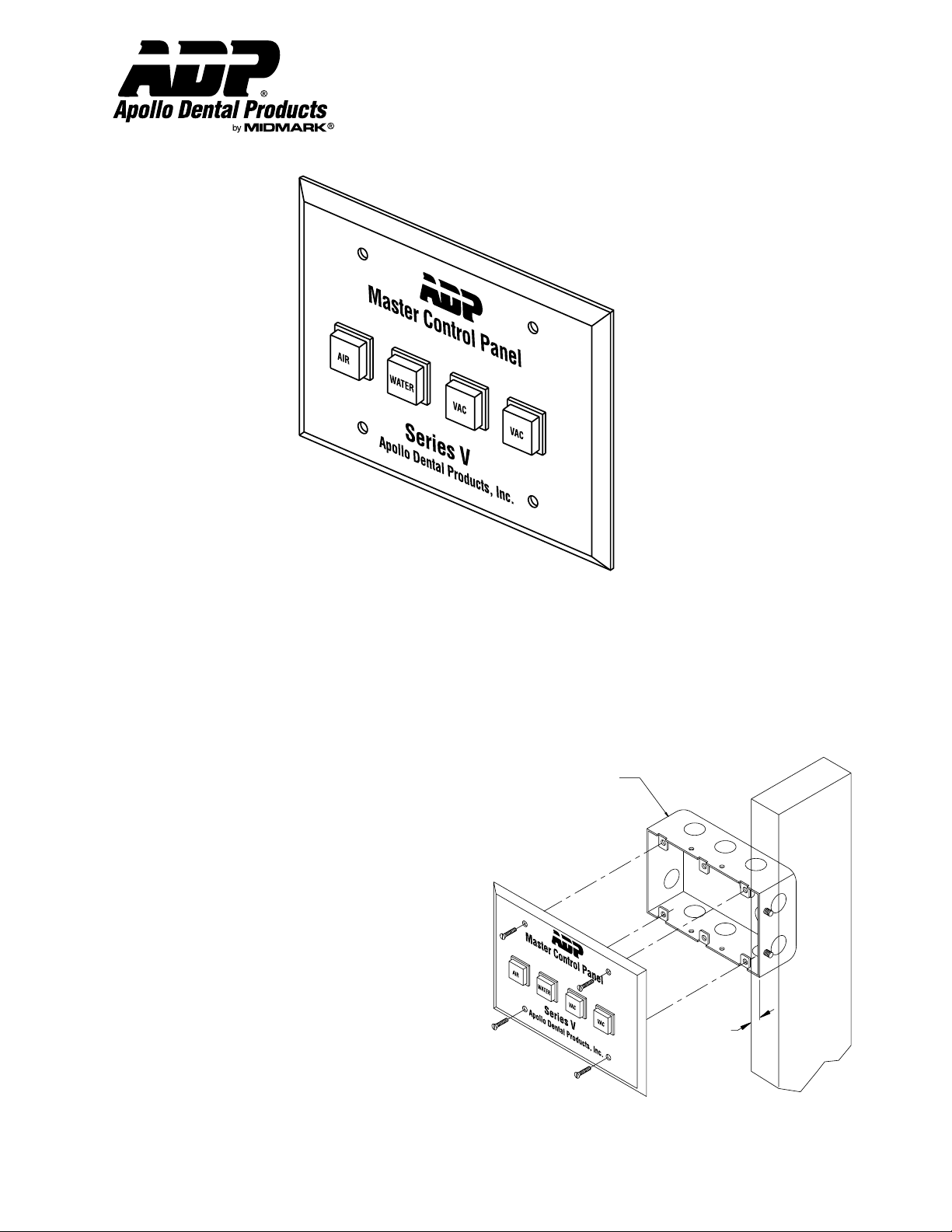
Description
The Apollo Dental Products Control Panel is designed to provide a convenient means of controlling dental equipment from inside the
office area. Features include lighted switches and an attractive brushed stainless steel mounting plate.
Master Control Panels include 50 feet of 18-3 bell wire with each switch, connecting fittings, and mounting fasteners.
Although the panel can be installed directly in drywall, many local codes require the use of a juction box. The juction box (not
provided) must be a standard three gang box measuring 2 1/2” deep by 4” high by 5 3/4” wide. With either mounting method, the
panel requires a standard three wire 24 VAC control circuit from each piece of equipment being controlled. ADP also manufactures a
complete line of remote contactor boxes for 24 VAC control.
Junction Box
(Not Provided)
Instructions For Junction Box Mounting
1. Prior to installation of sheet rock, mount the three gang
junction box to a stud as illustrated at right. The box should
be placed so that it’s front surface is set back 1/2” to 5/8”.
2. Run one 18-3 bell wire from each piece of equipment up to
the installed junction box.
3. Cut and install sheet rock.
4. Connectors are provided to complete the wiring of the control
panel by connecting wires to corresponding colored wires
from the Apollo low voltage contactor box(es).
1/2" To 5/8"
Set Back
5. Position the panel, then insert and tighten screws.
Apollo Dental Products, Inc. • 245 W. Dakota Ave. • Clovis, CA 93612 • Technical Support
559/292-1444 • 800/233-4151 • Fax 559/292-1555 • www.apollodental.com
Page 1
Box Mounted Control Panel Diagram
AMI60354 Rev. 4/00
Page 2
Installation & Operation
Series V Control Panel
Technical Service - (800) 233-4151
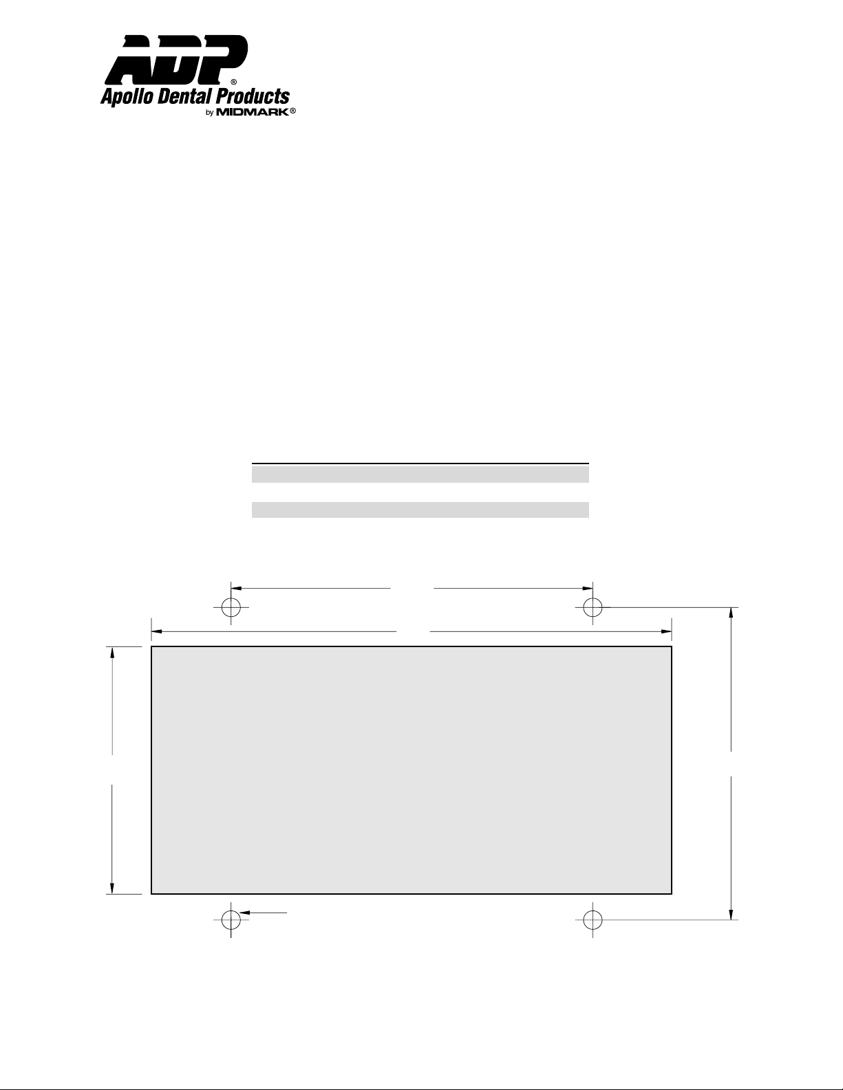
Instructions For Drywall Mounting
Warning: All Control Panels must be installed according to local codes.
1. Place the provided template on wall and mark the position of the four 3/16” diameter holes and the switch area.
2. Cut and remove the area from the drywall.
CAUTION: Do not cut hole larger than shown on the template.
3. Drill 3/16” holes.
4. Insert the provided anchors into the 3/16” holes.
5. Run one 18-3 bell wire from each piece of equipment to the area the panel is to be mounted.
6. Use the provided connectors to complete the wiring of the control panel. Attach each colored wire to the corresponding colored
wire from the Apollo contactor box(es).
7. Position the panel and insert screws. After the screw has contacted the mounting plate, use the chart below to find the additional
number of turns needed for proper expansion of the anchors.
Drywall Thickness Additional Turns After Contact
1/2” 5 - 7 Turns
3/4” 3 - 4 Turns
1” 1 - 2 Turns
21/32"
3
1/4
5
"
1/2
2
"
CUT OUT
5/32
3
"
THIS AREA
Drill Drywall Here (4 Places)
3/16" Diameter Hole
Drywall Mounting Template
Page 2 AMI60354 Rev. 4/00
Page 3

Installation & Operation
Series V Control Panel
Technical Service - (800) 233-4151
B = Blue
R = Red
W = White
Vac
R
W
Vac Water Air
R
W
B
B
Vac 1Vac 2
W
To WFB To Comp
R
B
R
W
B
Wiring Schematic (4 Switch)
Electrical Information
Note 1: As shown above, Control Panel equipped with a water control switch are wired such that water switch must be in the
“ON” position in order to start the vacuum pump(s). This feature is provided as a standard protective measure to ensure
that the vacuum pump(s) are not operated without water and thereby damaged.
Note 2: In panels without a water switch, the vacuum switch(es) are wired using the same configuration as shown on the air switch
above.
Trouble-Shooting Guide
Problem:
Problem:
Dental equipment does not start when switch is engaged.
Cause A: Broken or loose low voltage wire.
Corrective Action: 1. Check all wire connections.
Cause B: Defective switch.
Corrective Action: 1. Connect red and blue wires together at the contactor box, thus bypassing the switch.
2. Order new switch: SEA95227 “AIR”, SEA95228 “VAC”, SEA95229 “WATER”.
Dental equipment starts when switch is engaged but switch does not illuminate.
Cause A: Broken or loose wire.
Corrective Action: 1. Check all wire connections.
Cause B: Defective bulb.
Corrective Action: 1. Relamp switch by removing switch lens, then pulling bulb ejector lever located on inner
lower edge of switch. Press in new bulb (#SEA95225).
Warranty Information: 90 Days
All ADP accessories are thoroughly inspected and tested in accordance with rigid specifications and standards. Our accessories are guaranteed
against any defective material and workmanship from the date of shipment; provided that the installation, operation, and maintenance is done in
accordance with ADP procedures as outlined in our Installation and Maintenance Guides. Warranty cards must be returned to ADP within ten days of
installation to effect warranty. No other warranties or guarantees, expressed or implied are made.
ADP’s obligation under the warranty is to provide parts for the repair or, at its option, to provide the replacement product (excluding labor). All special,
incidental and/or consequential damages are excluded. We will not issue credit for accessories without first attempting to correct the problem in the
field. Written notice of breach of warranty must be given to ADP within the warranty period. The warranty does not cove damage resulting form
improper installation or maintenance, accident or misuse. The warranty does not cover damage resulting from the use of cleaning, disinfecting or
sterilizing chemicals and processes. Failure to follow instructions provided in ADP’s Installation and Maintenance Guides may void the warranty.
Page 3 AMI60354 Rev. 4/00
 Loading...